
Project Keiko Part VII - Rotor Seals Assembly

Thread Starter
Joined: May 2002
Posts: 5,972
Likes: 37
From: Ottawa, Soviet Canuckistan
Project Keiko Part VII - Rotor Seals Assembly
Parts I-VI of Project Keiko can be found here:
---Edit: Here are the other chapters of the project, for easy reference---
Project Keiko - Helping a friend
Project Keiko Part II - Exterior, Seals, and Engine Bay Teardown
Project Keiko Part III - Engine Removals
Project Keiko Part IV - Tri-Engine Teardowns I
Project Keiko Part V - Tri-Engine Teardowns II
Project Keiko Part VI - Engine Build I
Project Keiko Part VII - Rotor Seals Assembly
Project Keiko Part VIII - Week Of Crazyness
Project Keiko Part IX - End of Season Update
Project Keiko Part X - Spring 2009 Update
Project Keiko Part XI - Another Engine, Ready to Start
---/Edit---
So despite some setbacks (ie: not realizing that the Atkins Rebuild Kit "A" didn't have oil control ring springs and having to order some) I got to assembling the rotors with all their seals and springs tonight.
After the engine teardowns, I spent a lot of time re-reading old threads that I had found pertaining to engine builds. One of the most informative that also had a metric ton of pictures was by Aaron Cake, as part of his Project Tina:
Pics and Status Of (Project Tina's) Turbo-NA-Brigeport Engine Build
The one thing he didn't do though was a step-by-step guide to the assembly of the rotors. I decided that despite how incredibly tedious it would be to wipe the oil and vaseline off my hands every 30 seconds to take another picture I would do the tutorial anyway since nobody had done one.
I covered my workspace with clean shop towels and laid everything out so I could be organized and be sure that I wasn't missing anything:

I separated my work space into four areas. Across the top was for the Front Face of both rotors, across the middle was for the Rear Face of both rotors, with the Front Rotor on the left side and the Rear Rotor on the right.
This is something you really have to make VERY sure you get correct. Here's what I did to make sure I didn't get messed up:
1. The rotors have "F" or "R" stamped into the combustion recess. Find those markings and put the rotors on their respective sides of the table
2. Think about how the engine will be assembled, and you'll realize that the Front Face of the Front Rotor has the gear, while the Rear Face of the Rear Rotor has the gear. Keep this in mind.
If ever you get stuck, picture the front iron sitting on the engine stand and you placing the front rotor onto it, meshing with the gear. Then think about how the rear rotor has to have its gear face up before you put the rear iron down on it to mesh with the rear stat gear
3. Place the Front Rotor gear-side down and the Rear Rotor gear-side up, and do both the Rear Faces first, then flip them over and do both the Front Faces. So when you look at your rotors, both should be showing the opposite side.
It's always a good idea to constantly do a mental check to make sure you're doing the right thing. The oil control ring springs are colour coded (Blue for Rear Face, white/cream for Front Face) so you need to make sure they end up on the right sides!
Here are the Seals/Springs for the Front Face (gear-side) of the Front Rotor (notice that the springs are coloured cream/white)

and here are the Seals/Springs for the Rear Face (non-gear-side) of the Front Rotor (notice that the springs are coloured blue)

Here's a picture of the Front Rotor, with its Rear Face showing

... and a picture of the Rear Rotor, with its Rear Face showing

Now if you're not completely confused by this point, let's move on. If you are, go spend some time looking at how the engine goes together in Aaron's thread for Project Tina above and pay close attention to where the stationary gears are, where the rotor gears are, and keep in mind that "front" of the engine always faces the floor. Then come back and we'll move on
Jon
---Edit: Here are the other chapters of the project, for easy reference---
Project Keiko - Helping a friend
Project Keiko Part II - Exterior, Seals, and Engine Bay Teardown
Project Keiko Part III - Engine Removals
Project Keiko Part IV - Tri-Engine Teardowns I
Project Keiko Part V - Tri-Engine Teardowns II
Project Keiko Part VI - Engine Build I
Project Keiko Part VII - Rotor Seals Assembly
Project Keiko Part VIII - Week Of Crazyness
Project Keiko Part IX - End of Season Update
Project Keiko Part X - Spring 2009 Update
Project Keiko Part XI - Another Engine, Ready to Start
---/Edit---
So despite some setbacks (ie: not realizing that the Atkins Rebuild Kit "A" didn't have oil control ring springs and having to order some) I got to assembling the rotors with all their seals and springs tonight.
After the engine teardowns, I spent a lot of time re-reading old threads that I had found pertaining to engine builds. One of the most informative that also had a metric ton of pictures was by Aaron Cake, as part of his Project Tina:
Pics and Status Of (Project Tina's) Turbo-NA-Brigeport Engine Build
The one thing he didn't do though was a step-by-step guide to the assembly of the rotors. I decided that despite how incredibly tedious it would be to wipe the oil and vaseline off my hands every 30 seconds to take another picture I would do the tutorial anyway since nobody had done one.
I covered my workspace with clean shop towels and laid everything out so I could be organized and be sure that I wasn't missing anything:
I separated my work space into four areas. Across the top was for the Front Face of both rotors, across the middle was for the Rear Face of both rotors, with the Front Rotor on the left side and the Rear Rotor on the right.
This is something you really have to make VERY sure you get correct. Here's what I did to make sure I didn't get messed up:
1. The rotors have "F" or "R" stamped into the combustion recess. Find those markings and put the rotors on their respective sides of the table
2. Think about how the engine will be assembled, and you'll realize that the Front Face of the Front Rotor has the gear, while the Rear Face of the Rear Rotor has the gear. Keep this in mind.
If ever you get stuck, picture the front iron sitting on the engine stand and you placing the front rotor onto it, meshing with the gear. Then think about how the rear rotor has to have its gear face up before you put the rear iron down on it to mesh with the rear stat gear
3. Place the Front Rotor gear-side down and the Rear Rotor gear-side up, and do both the Rear Faces first, then flip them over and do both the Front Faces. So when you look at your rotors, both should be showing the opposite side.
It's always a good idea to constantly do a mental check to make sure you're doing the right thing. The oil control ring springs are colour coded (Blue for Rear Face, white/cream for Front Face) so you need to make sure they end up on the right sides!
Here are the Seals/Springs for the Front Face (gear-side) of the Front Rotor (notice that the springs are coloured cream/white)
and here are the Seals/Springs for the Rear Face (non-gear-side) of the Front Rotor (notice that the springs are coloured blue)
Here's a picture of the Front Rotor, with its Rear Face showing
... and a picture of the Rear Rotor, with its Rear Face showing
Now if you're not completely confused by this point, let's move on. If you are, go spend some time looking at how the engine goes together in Aaron's thread for Project Tina above and pay close attention to where the stationary gears are, where the rotor gears are, and keep in mind that "front" of the engine always faces the floor. Then come back and we'll move on
Jon
Last edited by vipernicus42; Jun 6, 2009 at 11:38 PM.
Thread Starter
Joined: May 2002
Posts: 5,972
Likes: 37
From: Ottawa, Soviet Canuckistan
First up are the Oil Seals.
The oil seals are rubber o-rings which fit inside metal carriers. We must remove the old seals carefully, lube up the new seals, and install them into the carriers equally as carefully.
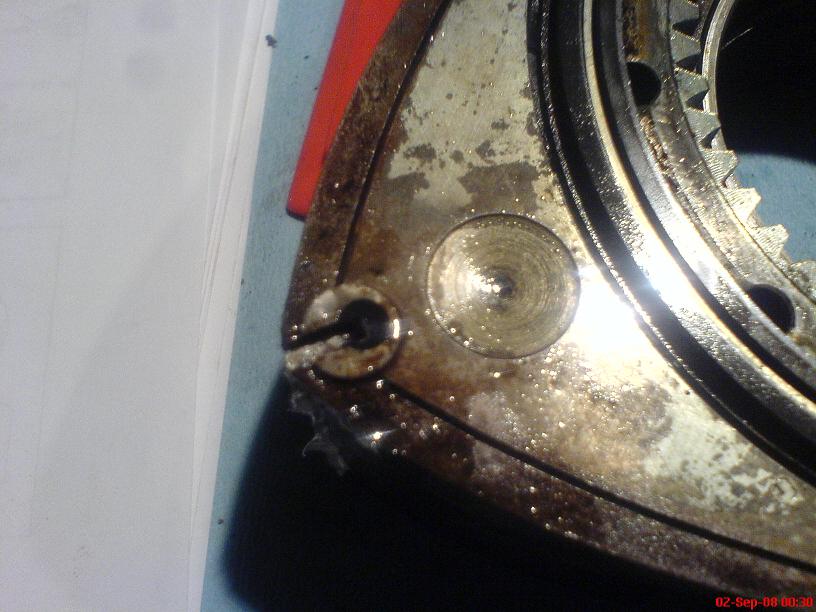
Here is a picture of the original Inner Oil Seal. As you can see it has flattened into the carrier and doesn't have the elasticity it once did.

I gently pried it out with the tip of a knife, being careful not to nick or damage the carrier. That left me with an empty carrier, which I cleaned with a shop towel

Here's what the new inner oil seal looks like beside its carrier

It's a good idea to oil up the seal prior to install. They are after all oil seals, and everything should be well lubricated so that it moves freely.
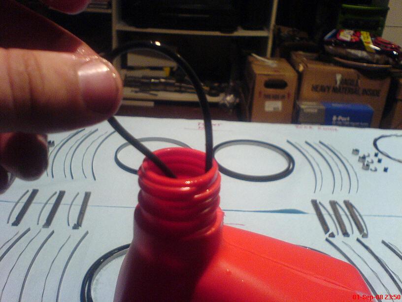
And here's what the new inner oil seal looks like after being installed into its carrier:

The oil seals are rubber o-rings which fit inside metal carriers. We must remove the old seals carefully, lube up the new seals, and install them into the carriers equally as carefully.
Here is a picture of the original Inner Oil Seal. As you can see it has flattened into the carrier and doesn't have the elasticity it once did.
I gently pried it out with the tip of a knife, being careful not to nick or damage the carrier. That left me with an empty carrier, which I cleaned with a shop towel
Here's what the new inner oil seal looks like beside its carrier
It's a good idea to oil up the seal prior to install. They are after all oil seals, and everything should be well lubricated so that it moves freely.
And here's what the new inner oil seal looks like after being installed into its carrier:
Thread Starter
Joined: May 2002
Posts: 5,972
Likes: 37
From: Ottawa, Soviet Canuckistan
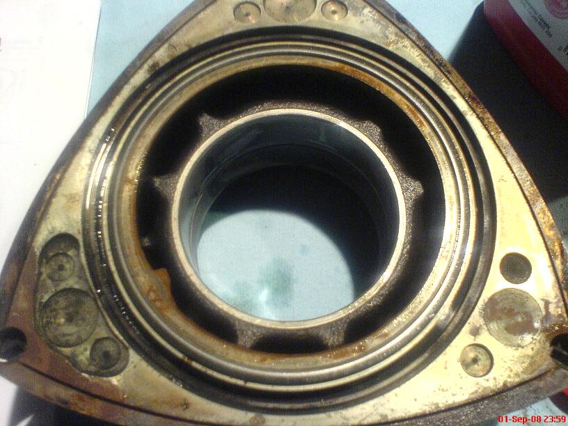
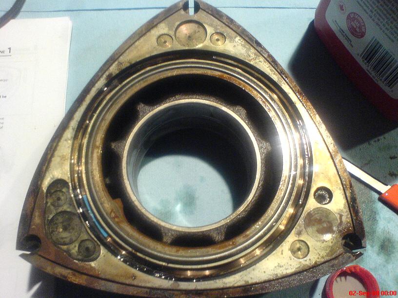
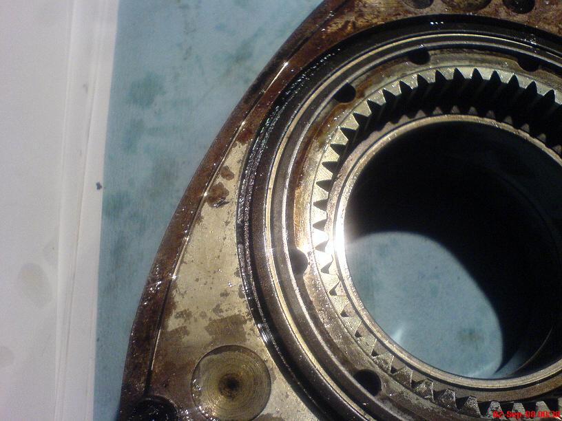
The Outer oil seals are very similar, with the one difference being that they fit around the inside of their metal carriers instead of the outside.
Here is the original outer oil seal:

And the dirty carrier as it looked once the oil seal was removed, before I cleaned it with a shop towel:

The new Outer Oil Seal installed:

And a picture of all eight (four inner, four outer) oil seal carriers with their new seals installed:

I applied a generous dose of oil to the carriers and seals by dipping my thumb and index finger in oil and running each one through my fingers. More oil is better as it eases installation.
Here is the original outer oil seal:
And the dirty carrier as it looked once the oil seal was removed, before I cleaned it with a shop towel:
The new Outer Oil Seal installed:
And a picture of all eight (four inner, four outer) oil seal carriers with their new seals installed:
I applied a generous dose of oil to the carriers and seals by dipping my thumb and index finger in oil and running each one through my fingers. More oil is better as it eases installation.
Thread Starter
Joined: May 2002
Posts: 5,972
Likes: 37
From: Ottawa, Soviet Canuckistan
Turning my attention back to the rotors, I installed the first spring.
I decided to do the rears of both rotors first, so I took the blue-painted springs, made sure that it was indeed the REAR face of both rotors showing (non-gear side for the front rotor, gear-side for the rear rotor) and placed the spring in its groove.
Again, it's a good idea to pour a little oil into the groove and spread it around before installing the spring and oil seals/carriers.
The paint side faces up, which means that the rounded edge of the spring faces towards the body of the rotor. You want that rounded edge to fit into the little depression that's made to hold it in place. If you can't see it, running the tip of the knife along the groove will help you find it.
Here's the inner oil control spring in place on the Rear face of the Front rotor:

With the spring in place, the "flat" end of the spring points upwards at you. Pick up your Oil Seal and Carrier and find the little "notch" it has in one side. Line that notch up with the "flat" end of the spring and place it evenly on top of the spring.
It will take some work to get the Oil Seals in place. It's helpful if you have a spare Oil Seal carrier around. Sometimes you might be able to get it in just pressing with your fingers, but often it will take a little more persuasion. Don't be tempted to use a metal hammer, that could seriously damage the carrier. If you have a wooden or plastic hammer you can use it gently. I actually used the corner of the vaseline container in some cases, and in others I used a spare oil control ring and one of the faces of a spare rotor (I didn't mind beating up the spare control ring, just don't use it directly on the one you're trying to install)
After some work, the oil seal and its carrier sit snugly in their groove, just barely peeking above the surface. You should be able to press it with your finger and have it move freely up and down.
The process is the same for the outer seal, as well as the inner and outer seal on each other rotor face for both rotors. The only difference is that when you're doing the "Front" faces, you use the cream-coloured springs instead of the blue ones.

I decided to do the rears of both rotors first, so I took the blue-painted springs, made sure that it was indeed the REAR face of both rotors showing (non-gear side for the front rotor, gear-side for the rear rotor) and placed the spring in its groove.
Again, it's a good idea to pour a little oil into the groove and spread it around before installing the spring and oil seals/carriers.
The paint side faces up, which means that the rounded edge of the spring faces towards the body of the rotor. You want that rounded edge to fit into the little depression that's made to hold it in place. If you can't see it, running the tip of the knife along the groove will help you find it.
Here's the inner oil control spring in place on the Rear face of the Front rotor:
With the spring in place, the "flat" end of the spring points upwards at you. Pick up your Oil Seal and Carrier and find the little "notch" it has in one side. Line that notch up with the "flat" end of the spring and place it evenly on top of the spring.
It will take some work to get the Oil Seals in place. It's helpful if you have a spare Oil Seal carrier around. Sometimes you might be able to get it in just pressing with your fingers, but often it will take a little more persuasion. Don't be tempted to use a metal hammer, that could seriously damage the carrier. If you have a wooden or plastic hammer you can use it gently. I actually used the corner of the vaseline container in some cases, and in others I used a spare oil control ring and one of the faces of a spare rotor (I didn't mind beating up the spare control ring, just don't use it directly on the one you're trying to install)
After some work, the oil seal and its carrier sit snugly in their groove, just barely peeking above the surface. You should be able to press it with your finger and have it move freely up and down.
The process is the same for the outer seal, as well as the inner and outer seal on each other rotor face for both rotors. The only difference is that when you're doing the "Front" faces, you use the cream-coloured springs instead of the blue ones.
Thread Starter
Joined: May 2002
Posts: 5,972
Likes: 37
From: Ottawa, Soviet Canuckistan
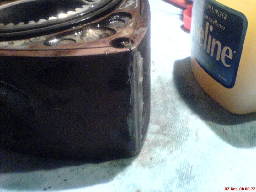
With the oil control rings/seals and springs installed, the next on the list are the Apex Seals.
Vaseline is used in capricious amounts to hold everything in place. I still use a liberal dose of oil on all the springs, but for all the seals vaseline is the best thing to hold them in their spots until you assemble the engine.
Here's an apex seal

And here's what it looks like completely covered in vaseline

You want the flat side of the apex seal to point towards the "Front" face of each rotor. That way when you're putting the engine together, you put the rotor down Front-first, then install the apex seal spring and assist piece before putting the next iron on.
You do want to make sure the apex seal has free movement in its groove, since you don't want it sticking or binding once the engine is built. Once you've confirmed it slides in its groove properly, hold it in place with more vaseline.
Here's the apex seal installed in its groove with lots of vaseline holding it in place
Next up are the corner seals. Each corner seal has a rubber insert which must be installed. I covered them in vaseline and slid them into place in the corner seals
Here is the corner seal beside its rubber insert

and here is what it looks like with the insert installed

Vaseline is used in capricious amounts to hold everything in place. I still use a liberal dose of oil on all the springs, but for all the seals vaseline is the best thing to hold them in their spots until you assemble the engine.
Here's an apex seal
And here's what it looks like completely covered in vaseline
You want the flat side of the apex seal to point towards the "Front" face of each rotor. That way when you're putting the engine together, you put the rotor down Front-first, then install the apex seal spring and assist piece before putting the next iron on.
You do want to make sure the apex seal has free movement in its groove, since you don't want it sticking or binding once the engine is built. Once you've confirmed it slides in its groove properly, hold it in place with more vaseline.
Here's the apex seal installed in its groove with lots of vaseline holding it in place
Next up are the corner seals. Each corner seal has a rubber insert which must be installed. I covered them in vaseline and slid them into place in the corner seals
Here is the corner seal beside its rubber insert
and here is what it looks like with the insert installed
Thread Starter
Joined: May 2002
Posts: 5,972
Likes: 37
From: Ottawa, Soviet Canuckistan
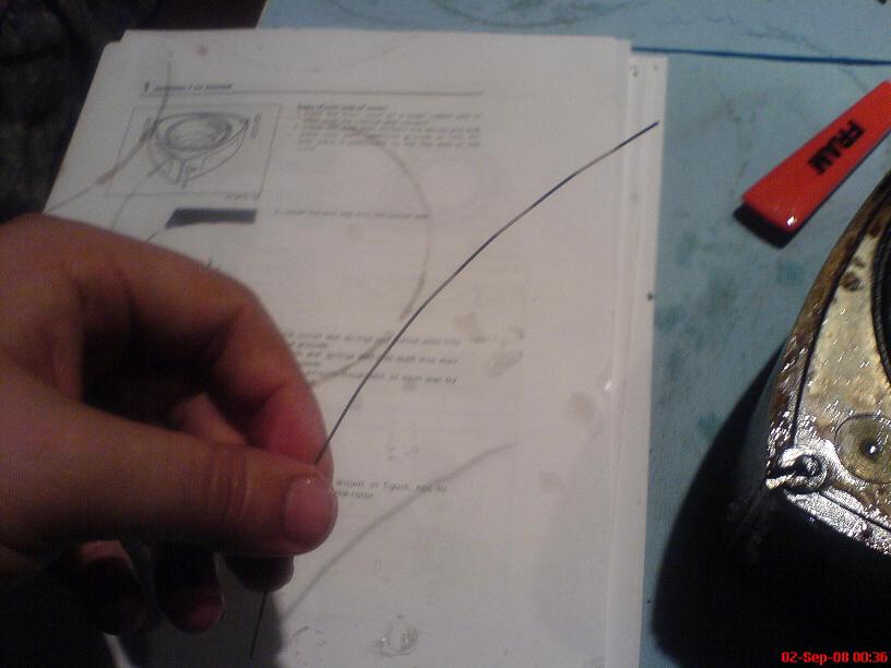
One thing that is nice about the Atkins Rotary rebuild kits is that even the cheapest budget kit (The "Rebuild Kit 'A'") have 3rd Gen corner seal springs which are a VAST improvement over the stock 12a corner seal springs. I threw all mine out more than a week before I took these pictures so I don't have one to compare but they're basically very small, thin pieces of wire bent into a similar shape to the ones you see here.
I oiled up the corner seal springs well and placed them in their respective spots.
Here's one of the corner seals all oiled up ready to be installed

And here's one installed in its spot (it's kind of hard to see, but it's there, with the opening towards the apex seal of course)

Now one thing you have to keep in mind is that the apex seal springs don't get installed now - they get installed after the rotor and its rotor housing are in place. If the apex seal springs were installed now, it would be nearly impossible to get the rotor housing in place over top of the rotor because the apex seals would be sticking out too far.
Why am I mentioning this now? Because if all of the corner seals were installed, we wouldn't be able to install the apex seal springs! The corner seals have to come out of the "rear" side of the rotor for the apex seal springs to slide down in place.
I chose to install all the corner seals anyway for two reasons. One, I wanted to make sure they all slid easily and comfortably into their spots, and Two, I wanted a good way to know where everything was since I won't be assembling the engine for at least 24-48hrs. When it comes time to assemble the engine I'll remove the corner seals from the "rear" side of the rotors, slide the apex seal springs in place, and reinstall the corner seals along with the apex seal assist pieces.
Here's what the corner seal looks like when it's installed in its spot:
And here is one rotor with all of its corner seals installed:

I oiled up the corner seal springs well and placed them in their respective spots.
Here's one of the corner seals all oiled up ready to be installed
And here's one installed in its spot (it's kind of hard to see, but it's there, with the opening towards the apex seal of course)
Now one thing you have to keep in mind is that the apex seal springs don't get installed now - they get installed after the rotor and its rotor housing are in place. If the apex seal springs were installed now, it would be nearly impossible to get the rotor housing in place over top of the rotor because the apex seals would be sticking out too far.
Why am I mentioning this now? Because if all of the corner seals were installed, we wouldn't be able to install the apex seal springs! The corner seals have to come out of the "rear" side of the rotor for the apex seal springs to slide down in place.
I chose to install all the corner seals anyway for two reasons. One, I wanted to make sure they all slid easily and comfortably into their spots, and Two, I wanted a good way to know where everything was since I won't be assembling the engine for at least 24-48hrs. When it comes time to assemble the engine I'll remove the corner seals from the "rear" side of the rotors, slide the apex seal springs in place, and reinstall the corner seals along with the apex seal assist pieces.
Here's what the corner seal looks like when it's installed in its spot:
And here is one rotor with all of its corner seals installed:
Thread Starter
Joined: May 2002
Posts: 5,972
Likes: 37
From: Ottawa, Soviet Canuckistan
Lastly, we have the Side Seals and their Springs.
Oil up the side seal and insert it into its groove. Side Seal grooves are slightly different lengths for each side of each rotor in existence due to the way rotors are made (cast?). The side seal springs are purposefully made shorter than any side seal groove could possibly be, so it's not a concern for the springs, but it is an issue for the side seals themselves
Side Seal Spring Oiled Up
Side Seal Spring Installed
The side seals themselves should be clearance, or if you're re-using your side seals on a rebuild, you should have stored them in a compartmented box where each side of each face of each rotor was kept track of. New side seals are made longer than any side seal groove should be and have to be filed down to fit their groove. Old ones should be placed back in exactly the same groove they were removed from.
In this case, I tore apart three engines, broke a *bunch* of side seals that were seized into their grooves, and didn't keep track of which grooves the intact ones came out of. The result is that some of these side seals may not be properly clearanced for their grooves. This will mean that I will have lower compression on some rotor faces than I would like, since combustion gasses will leak past the side seal in the tenths-of-a-millimetre worth of clearance gap there is between the side seal and the corner seal. For this budget build, I can live with that, but you definitely want to spend some time clearancing your seals for any other engine build. On new ones, it's not even an option as they won't fit in the grooves - they're too long on purpose from the factory.
As always, use lots of vaseline to hold everything in place (I didn't get a picture of the side seal all gunked up, but here's the seal with the vaseline in the background)

Here's the side seal installed in its groove

And here are all of the side seals done:

That completes the seal assembly for both rotors. I used various things to prop them up to keep them off the shop towels since the shop towels would absorb some vaseline and when I went to pick up the rotor in one or two day's time some seals might fall out. As it is I'll keep an eye on them to make sure they stay where they are until engine assembly.
Here are both of the rotors, all ready to go:

Oil up the side seal and insert it into its groove. Side Seal grooves are slightly different lengths for each side of each rotor in existence due to the way rotors are made (cast?). The side seal springs are purposefully made shorter than any side seal groove could possibly be, so it's not a concern for the springs, but it is an issue for the side seals themselves
Side Seal Spring Oiled Up
Side Seal Spring Installed
The side seals themselves should be clearance, or if you're re-using your side seals on a rebuild, you should have stored them in a compartmented box where each side of each face of each rotor was kept track of. New side seals are made longer than any side seal groove should be and have to be filed down to fit their groove. Old ones should be placed back in exactly the same groove they were removed from.
In this case, I tore apart three engines, broke a *bunch* of side seals that were seized into their grooves, and didn't keep track of which grooves the intact ones came out of. The result is that some of these side seals may not be properly clearanced for their grooves. This will mean that I will have lower compression on some rotor faces than I would like, since combustion gasses will leak past the side seal in the tenths-of-a-millimetre worth of clearance gap there is between the side seal and the corner seal. For this budget build, I can live with that, but you definitely want to spend some time clearancing your seals for any other engine build. On new ones, it's not even an option as they won't fit in the grooves - they're too long on purpose from the factory.
As always, use lots of vaseline to hold everything in place (I didn't get a picture of the side seal all gunked up, but here's the seal with the vaseline in the background)
Here's the side seal installed in its groove
And here are all of the side seals done:
That completes the seal assembly for both rotors. I used various things to prop them up to keep them off the shop towels since the shop towels would absorb some vaseline and when I went to pick up the rotor in one or two day's time some seals might fall out. As it is I'll keep an eye on them to make sure they stay where they are until engine assembly.
Here are both of the rotors, all ready to go:
Trending Topics
Thread Starter
Joined: May 2002
Posts: 5,972
Likes: 37
From: Ottawa, Soviet Canuckistan
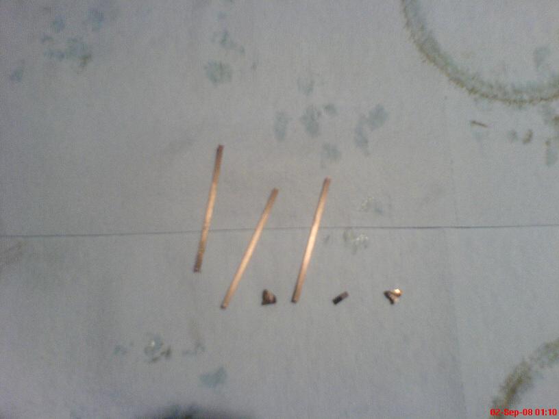
As mentioned before this leaves us with two things for leftovers: The apex seal springs and the apex seal assist pieces. (There are six of each total, this picture is just for one rotor's worth)
When we go to build the engine, the corner seals will be removed from the rear face of the rotor, the apex seal springs will be pushed into place, the corner seals will be reinstalled and the assist pieces will be put into place.
I may use a dab of crazyglue to glue the assist pieces to the apex seals, since I've heard they can be a little finicky. My assist pieces in particular are worn down and many of them have worn more than the apex seal they're attached to, making for a not-so-snug fit. I'll have to be careful since if the assist pieces aren't seated properly you'll end up with a LOT more compressed air/fuel blowing by the apex seal than you'd like. Possibly enough to prevent the engine from running!
But we'll cross that bridge when we get there. For now the rotors are done, the post is made, it's 3am and I've got work in 4hrs, so I'm going to bed!
Jon
Thread Starter
Joined: May 2002
Posts: 5,972
Likes: 37
From: Ottawa, Soviet Canuckistan
Apex seals are all below spec
New: 8.5mm
Wear Limit: 7.0mm
My Best Seal: 6.91mm
Side Seals aren't clearanced to match their grooves, and the assist-pieces for the apex seals leave something to be desired. There's at least 1-2mm of chrome flake along the sides of both rotor housings, too.
Nevertheless, I'm confidant that the engine will run, and since my expectations for it are low (start, run, drive the car for one season) I will be happy with pretty much any result other than total engine failure on first crank.
It's definitely a ton of fun though. I've always wanted to undertake an engine rebuild project, but never wanted to do it on my "main" seven. If I wasn't trying to get this thing running by winter (and if I wasn't so poor) I'd get some tools and try my hand at making it a half-bridge or something.
Jon
Double Ds for me to share
Joined: Mar 2005
Posts: 513
Likes: 4
From: abbotsford
The rotary specialist that trained me to build engines never install the apex seals into the rotor prior to building the engine. Every other seal was installed in the rotor till it was time to actually build the engine. Just before engine assembly he taught me to crazy glue the corner piece of the apex seal to the main piece of the apex seal and let it dry. After the rotor was set on to the front plate we would make sure the corner seals were still lined up and we would install the rotor housing then we would install the apex seal and spring into the rotor at once. When assembly was done and we began to torque the bolts down you could hear the apex seals separating and seating into the rotor. We have never had a problem with a engine built this way. As long as it works I'm sure everyone has a different way of doing it...
Thread Starter
Joined: May 2002
Posts: 5,972
Likes: 37
From: Ottawa, Soviet Canuckistan
The rotary specialist that trained me to build engines never install the apex seals into the rotor prior to building the engine. Every other seal was installed in the rotor till it was time to actually build the engine. Just before engine assembly he taught me to crazy glue the corner piece of the apex seal to the main piece of the apex seal and let it dry. After the rotor was set on to the front plate we would make sure the corner seals were still lined up and we would install the rotor housing then we would install the apex seal and spring into the rotor at once. When assembly was done and we began to torque the bolts down you could hear the apex seals separating and seating into the rotor. We have never had a problem with a engine built this way. As long as it works I'm sure everyone has a different way of doing it...
Yeah more than one person has told me that they do it that way including some rather reputable builders. I did it this way because I was following the FSM instructions combined with Aaron's thread. The difference between the two being that the FSM says to use a rubber o-ring to hold the apex seals in place while Aaron used capricious amounts of vaseline.
Unfortunately it'll be quite a while before I know how well (or even if) the engine runs. I need a combination of good weather and more money, both of which are in short supply lately.
Jon

Thread
Thread Starter
Forum
Replies
Last Post
trickster
2nd Generation Specific (1986-1992)
25
Jul 1, 2023 04:40 PM
KAL797
Test Area 51
0
Aug 11, 2015 03:47 PM