
Project Keiko Part V - Tri-Engine Teardowns II

Thread Starter
Joined: May 2002
Posts: 5,972
Likes: 37
From: Ottawa, Soviet Canuckistan
Project Keiko Part V - Tri-Engine Teardowns II
---Edit: Here are the other chapters of the project, for easy reference---
Project Keiko - Helping a friend
Project Keiko Part II - Exterior, Seals, and Engine Bay Teardown
Project Keiko Part III - Engine Removals
Project Keiko Part IV - Tri-Engine Teardowns I
Project Keiko Part V - Tri-Engine Teardowns II
Project Keiko Part VI - Engine Build I
Project Keiko Part VII - Rotor Seals Assembly
Project Keiko Part VIII - Week Of Crazyness
Project Keiko Part IX - End of Season Update
Project Keiko Part X - Spring 2009 Update
Project Keiko Part XI - Another Engine, Ready to Start
Project Keiko Part XII - Up For Sale
---/Edit---
So I finally got around to tearing the engines apart. The results weren't nearly as good as I had hoped, but we took lots of pictures so let's get to it, shall we?
The first engine we took apart was the absolute NASTIEST of the three, so most of my procedural "how-to" pictures came from it. I know folks like seeing really horrible looking engine internals, so I won't disappoint!
The first step, after stripping the engine like we did in the last thread, is to remove the tension bolts holding the engine together. In the shop manual there is an order in which the bolts have to come out. While it's undoubtedly important, it's not nearly as important as it is when you're putting the engine together. If I get a chance later I'll find a reference picture for the order in which they're removed but I don't think there's a huge issue with going in the "wrong" order during removal (I could be wrong, but on this budget engine build, I don't think it's crucial)
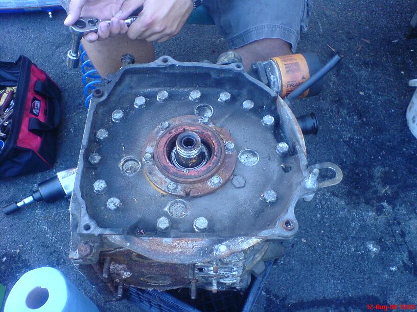
I bought an impact wrench when we started tearing down the engines initially and it has served me well. The only issue I have is that my air tank is so incredibly small that it can't hold high pressure long enough to crack the really stubborn bolts, but I'm telling you the impact wrench is worth its weight in gold some days!
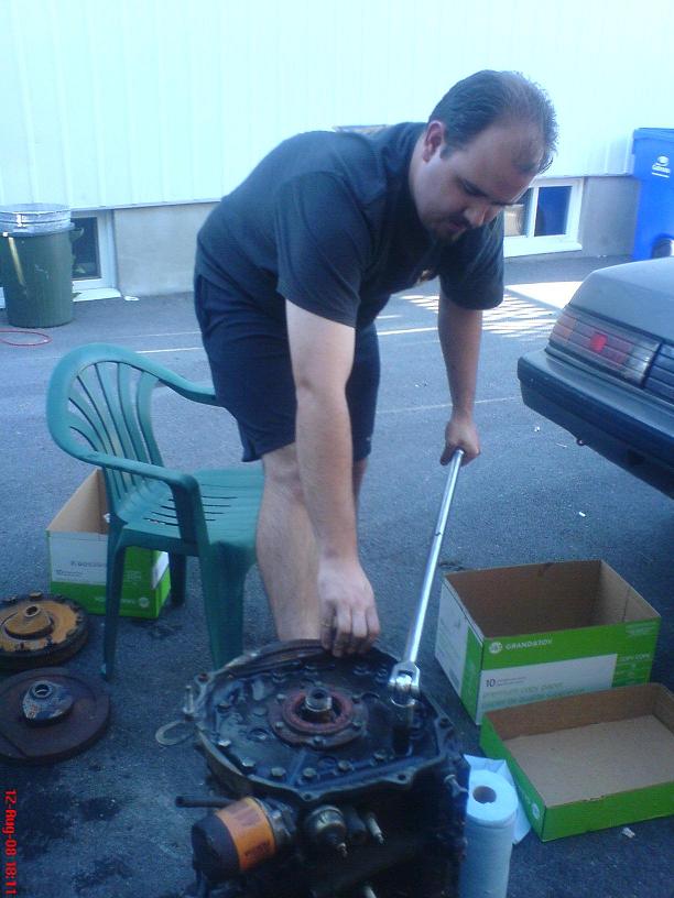
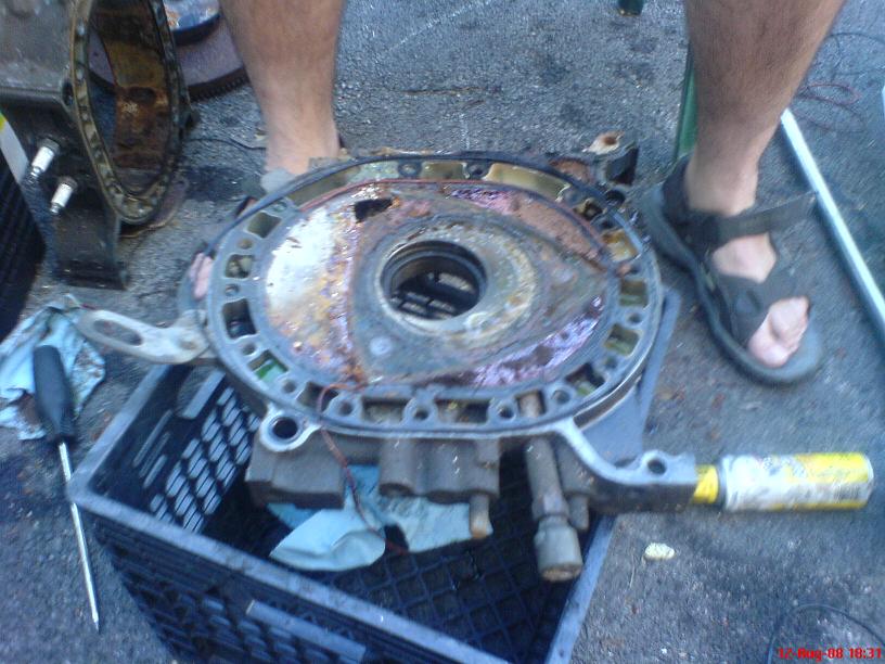
But... where the impact fails because of my small 3gallon air tank, the 3ft breaker bar comes to the rescue!
Don't forget these two bolts. They're cleverly hidden in plain sight, and if you don't notice them you could be swearing quite a bit at why the rear iron won't come off.
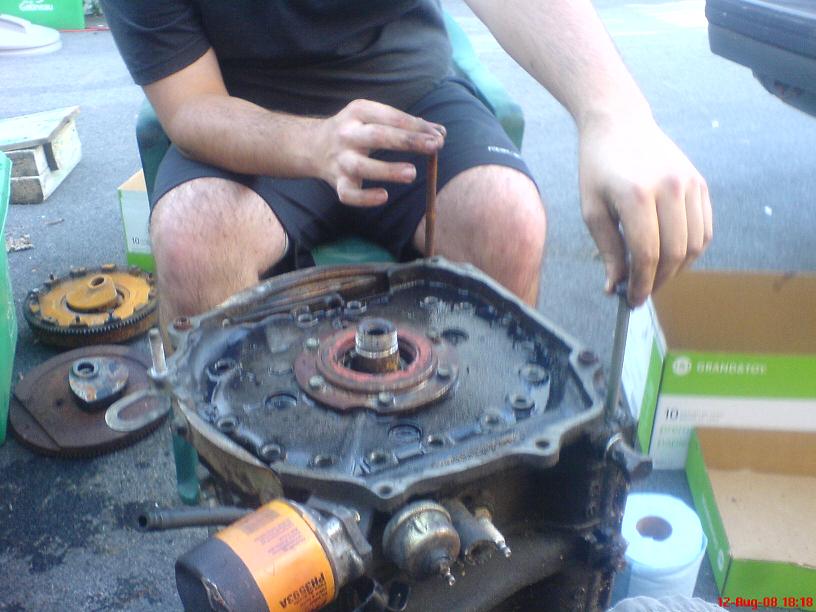
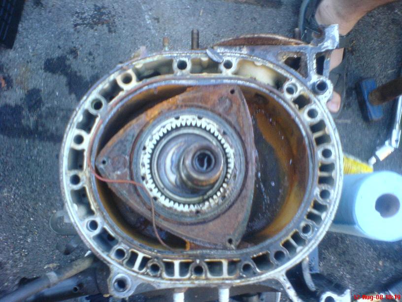
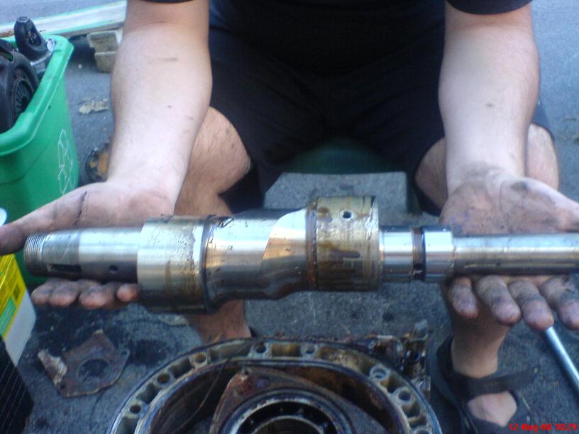
Once the tension bolts have been removed, there's only one thing left to do before the rear iron can be removed - you have to remove the "key" in the slot in the eccentric shaft that helped orient the flywheel in the right direction. I didn't get a picture of it here, but you can see in the next image, sitting on the "upper" edge of the rotor housing ("upper" being relative to the orientation of the picture).
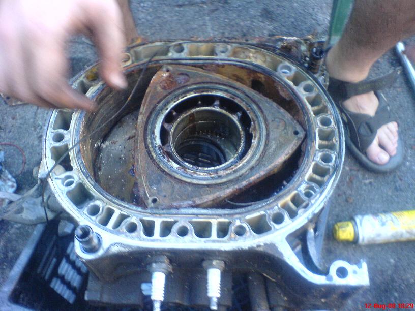
With the key out, the rear iron should pull straight up and off. Of course with engines that have been assembled for 20+ years and possibly sitting in garages, front yards, whatever, this may be a little harder than it sounds. A few gentle upward taps with a hammer on the outer edges (be careful not to mar mating surfaces) should knock it loose, then you can gently force it up evenly on both sides. It pulls off to reveal the rear rotor and rotor housing, which in this case are completely rusted and totally nasty looking
Project Keiko - Helping a friend
Project Keiko Part II - Exterior, Seals, and Engine Bay Teardown
Project Keiko Part III - Engine Removals
Project Keiko Part IV - Tri-Engine Teardowns I
Project Keiko Part V - Tri-Engine Teardowns II
Project Keiko Part VI - Engine Build I
Project Keiko Part VII - Rotor Seals Assembly
Project Keiko Part VIII - Week Of Crazyness
Project Keiko Part IX - End of Season Update
Project Keiko Part X - Spring 2009 Update
Project Keiko Part XI - Another Engine, Ready to Start
Project Keiko Part XII - Up For Sale
---/Edit---
So I finally got around to tearing the engines apart. The results weren't nearly as good as I had hoped, but we took lots of pictures so let's get to it, shall we?
The first engine we took apart was the absolute NASTIEST of the three, so most of my procedural "how-to" pictures came from it. I know folks like seeing really horrible looking engine internals, so I won't disappoint!
The first step, after stripping the engine like we did in the last thread, is to remove the tension bolts holding the engine together. In the shop manual there is an order in which the bolts have to come out. While it's undoubtedly important, it's not nearly as important as it is when you're putting the engine together. If I get a chance later I'll find a reference picture for the order in which they're removed but I don't think there's a huge issue with going in the "wrong" order during removal (I could be wrong, but on this budget engine build, I don't think it's crucial)
I bought an impact wrench when we started tearing down the engines initially and it has served me well. The only issue I have is that my air tank is so incredibly small that it can't hold high pressure long enough to crack the really stubborn bolts, but I'm telling you the impact wrench is worth its weight in gold some days!
But... where the impact fails because of my small 3gallon air tank, the 3ft breaker bar comes to the rescue!
Don't forget these two bolts. They're cleverly hidden in plain sight, and if you don't notice them you could be swearing quite a bit at why the rear iron won't come off.
Once the tension bolts have been removed, there's only one thing left to do before the rear iron can be removed - you have to remove the "key" in the slot in the eccentric shaft that helped orient the flywheel in the right direction. I didn't get a picture of it here, but you can see in the next image, sitting on the "upper" edge of the rotor housing ("upper" being relative to the orientation of the picture).
With the key out, the rear iron should pull straight up and off. Of course with engines that have been assembled for 20+ years and possibly sitting in garages, front yards, whatever, this may be a little harder than it sounds. A few gentle upward taps with a hammer on the outer edges (be careful not to mar mating surfaces) should knock it loose, then you can gently force it up evenly on both sides. It pulls off to reveal the rear rotor and rotor housing, which in this case are completely rusted and totally nasty looking
Last edited by vipernicus42; Aug 25, 2009 at 07:46 PM.
Thread Starter
Joined: May 2002
Posts: 5,972
Likes: 37
From: Ottawa, Soviet Canuckistan
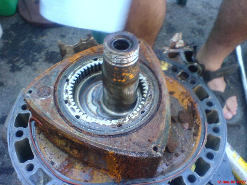
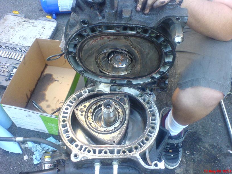
The rear rotor housing is now only held in place by the two tubular dowel pins which go through it and into the intermediate plate about half an inch. There is a dowel pin remover tool, but since they're usually not in there very tight (oiled then just slid into place snugly by hand) you can actually remove the rotor housing by sliding it straight up and off. Again, gentle persuation may be needed to break the seal that has formed over time between the rotor housing and the intermediate plate. Once you get the rear rotor housing off you can remove the dowel pins from their holes and place them aside.
That leaves the rotor sitting on the intermediate plate. Now is the time where normally you have to be very careful losing seals or having them get mixed up. With this engine they were all rusted in place so badly, I ended up just leaving this set of seals in the rotor and throwing the rotors out with all the seals on them. With a good engine you want to have some sort of compartmented box handy. Using a marker that can draw on metal, number everything and match the numbers to the compartments in the box.
Side seals are filed down to exactly fit the length of their groove, which can be longer or shorter just because of the way the rotor was cast. That's why it's vitally important that if you're planning to re-use the seals you keep track of which seal came from exactly which place on which rotor from which engine.
Side Seals, Corner Seals, Apex Seals and Corner Pieces should all be identified and removed, though if you're able to move the rotor into a box without losing any seals or their positions in the process you can do that and save the labeling and sorting for later (which is what I did). For this budget build, since I'll be measuring and re-clearancing all the seals anyway, I didn't bother with the tedium of matching and labeling. I may regret that later.
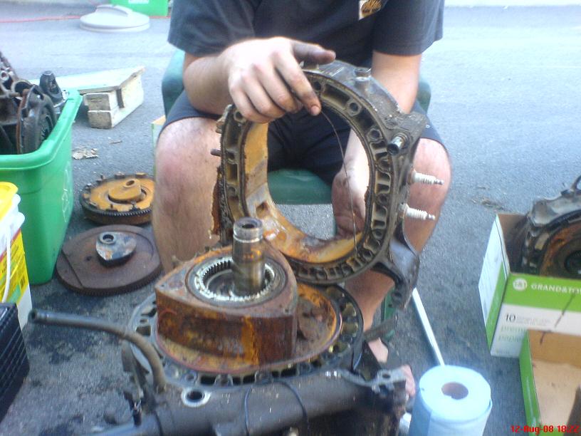
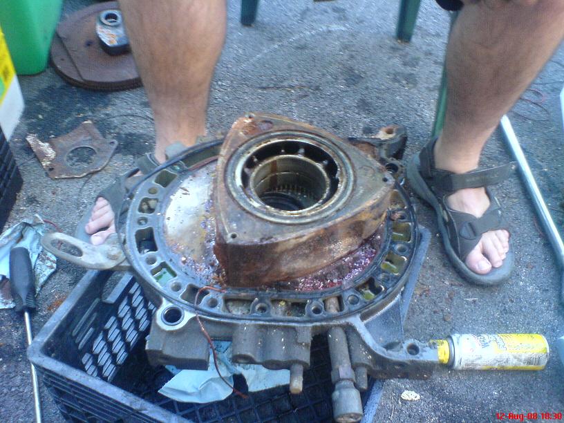
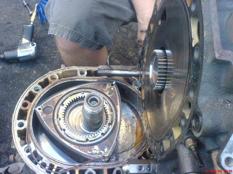
With the rotor out of the way, the intermediate plate is ready to be removed. This one is very tricky since (as you can see in the picture) the rear lobe of the e-shaft gets in the way of the plate's ability to come off. This is a 2-person job. One person has to lift the shaft slightly while the other lifts the housing and maneuvers it so that the rear lobe can fit through the hole in the intermediate plate. The person holding the shaft will have to grab the shaft underneath the housing as you lift it up so that their top hand can get out of the way without just dropping the shaft.
and that's how the centre iron comes off.

Then you can remove the e-shaft, being careful not to damage it or the main bearing in the front stationary gear.
That leaves the rotor sitting on the intermediate plate. Now is the time where normally you have to be very careful losing seals or having them get mixed up. With this engine they were all rusted in place so badly, I ended up just leaving this set of seals in the rotor and throwing the rotors out with all the seals on them. With a good engine you want to have some sort of compartmented box handy. Using a marker that can draw on metal, number everything and match the numbers to the compartments in the box.
Side seals are filed down to exactly fit the length of their groove, which can be longer or shorter just because of the way the rotor was cast. That's why it's vitally important that if you're planning to re-use the seals you keep track of which seal came from exactly which place on which rotor from which engine.
Side Seals, Corner Seals, Apex Seals and Corner Pieces should all be identified and removed, though if you're able to move the rotor into a box without losing any seals or their positions in the process you can do that and save the labeling and sorting for later (which is what I did). For this budget build, since I'll be measuring and re-clearancing all the seals anyway, I didn't bother with the tedium of matching and labeling. I may regret that later.
With the rotor out of the way, the intermediate plate is ready to be removed. This one is very tricky since (as you can see in the picture) the rear lobe of the e-shaft gets in the way of the plate's ability to come off. This is a 2-person job. One person has to lift the shaft slightly while the other lifts the housing and maneuvers it so that the rear lobe can fit through the hole in the intermediate plate. The person holding the shaft will have to grab the shaft underneath the housing as you lift it up so that their top hand can get out of the way without just dropping the shaft.
and that's how the centre iron comes off.
Then you can remove the e-shaft, being careful not to damage it or the main bearing in the front stationary gear.
Thread Starter
Joined: May 2002
Posts: 5,972
Likes: 37
From: Ottawa, Soviet Canuckistan
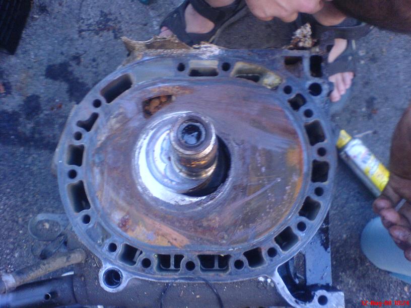
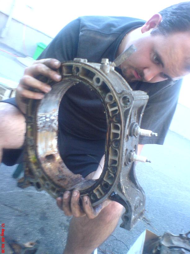
With the e-shaft out, the front rotor housing can be removed the same way the rear one was, lifting it straight up so that it will side off the tubular dowel pins.
Then the front rotor can be removed, taking the same care to make sure the seals don't get lost or mixed up as with the first rotor.
And that just leaves the front housing, sitting on our engine stand (a milk crate in this case)
Then the front rotor can be removed, taking the same care to make sure the seals don't get lost or mixed up as with the first rotor.
And that just leaves the front housing, sitting on our engine stand (a milk crate in this case)
Thread Starter
Joined: May 2002
Posts: 5,972
Likes: 37
From: Ottawa, Soviet Canuckistan
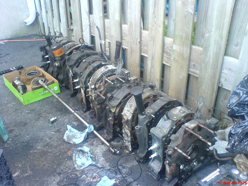
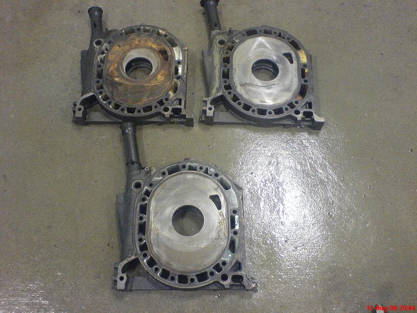
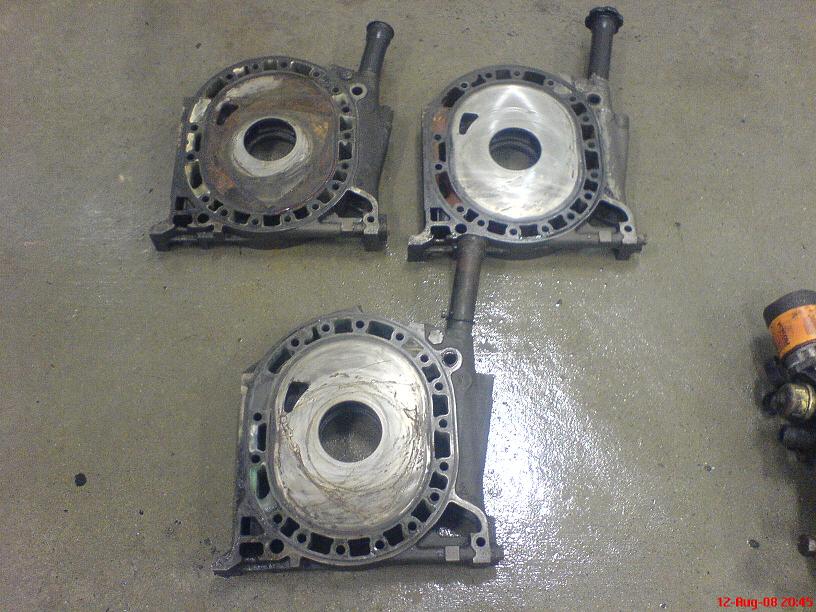
So by now you're probably thinking "Holy Crap, that engine is toast, I wonder how the other two looked"
The good news is that the first engine was by far the worst. The bad news is that the other two engines weren't *perfect*.
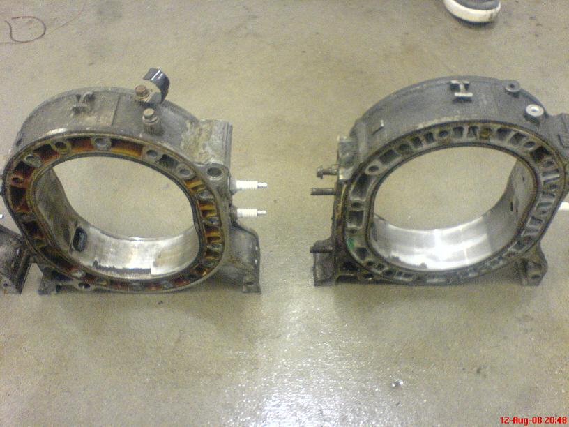
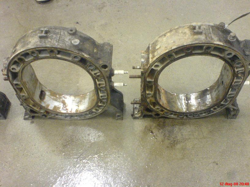
Here's what Engine #2 looked like with the rear iron off
And here's what Engine #3 looked like with its rear iron off
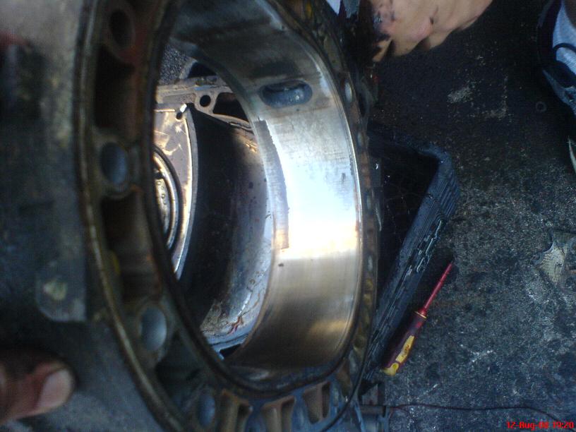
I'm fairly confidant that between Engines #2 and #3 I can get a full set of usable irons. Rotor housings on the other hand were a different story. Pretty much all of them had chrome flaking:
At the end of the day, we finally got all three engines apart. It didn't take long actually, since I wasn't too worried about the seals getting mixed up for this build, they took about 30-45mins each to tear down from where they started on stands.
The good news is that the first engine was by far the worst. The bad news is that the other two engines weren't *perfect*.
Here's what Engine #2 looked like with the rear iron off
And here's what Engine #3 looked like with its rear iron off
I'm fairly confidant that between Engines #2 and #3 I can get a full set of usable irons. Rotor housings on the other hand were a different story. Pretty much all of them had chrome flaking:
At the end of the day, we finally got all three engines apart. It didn't take long actually, since I wasn't too worried about the seals getting mixed up for this build, they took about 30-45mins each to tear down from where they started on stands.
Thread Starter
Joined: May 2002
Posts: 5,972
Likes: 37
From: Ottawa, Soviet Canuckistan
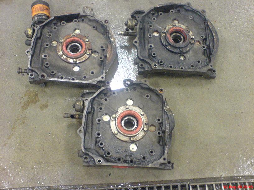
So I took all the housings down to the local self-wash, blasted them with the pressure washer, then spent a good long time with the compressed air dryer making sure there was no moisture left so that they wouldn't rust quickly. They got a light wipe with oil before being brought inside.
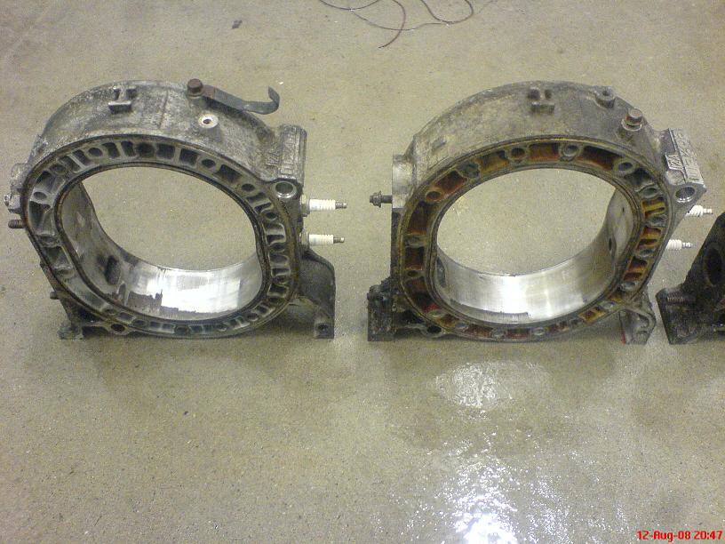
So let's take a close look at what we got from these three engines. First the Rear Irons (Housings, Plates, whatever you would like to call them)
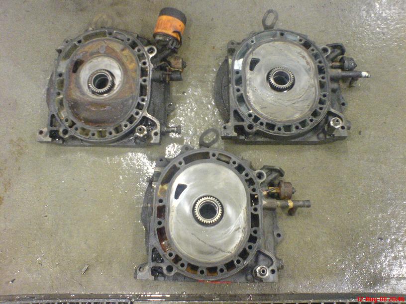
Now the Intermediate Housings (Middle Irons, Plates, whatever)
And the Front Housings
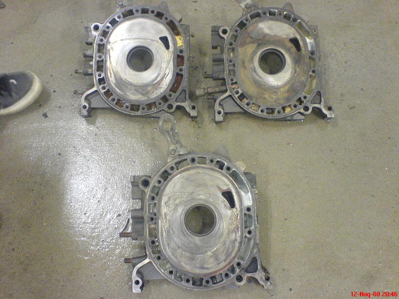
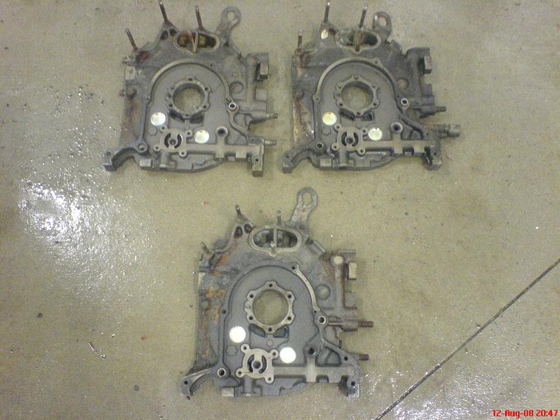
So I'll have to spend some serious time with solvent and a very light abrasive or brush to get the carbon off of these housings but I think that I can get a set of salvageable housings out of this. The cleanest ones don't have any large grooves that my nails can feel, other than the obvious stuff that you can see sitting on top of the surface that needs to be removed.
So let's take a close look at what we got from these three engines. First the Rear Irons (Housings, Plates, whatever you would like to call them)
Now the Intermediate Housings (Middle Irons, Plates, whatever)
And the Front Housings
So I'll have to spend some serious time with solvent and a very light abrasive or brush to get the carbon off of these housings but I think that I can get a set of salvageable housings out of this. The cleanest ones don't have any large grooves that my nails can feel, other than the obvious stuff that you can see sitting on top of the surface that needs to be removed.
Thread Starter
Joined: May 2002
Posts: 5,972
Likes: 37
From: Ottawa, Soviet Canuckistan
... But for the rotor housings, I didn't get off nearly as lucky. All these housings suck. They all have chrome flake except the ones from the rusty engine, and I don't know if those will clean up well enough to be useful but I'm not betting on it. I will try though. It looks like the best set of rotor housings I have is out at RPM Motorsports in Kitchener.. they have a little chrome flake, but not nearly as much as these. Less than 1mm deep and less than 10mm long, each housing. It would be enough to last for this budget build, I hope.
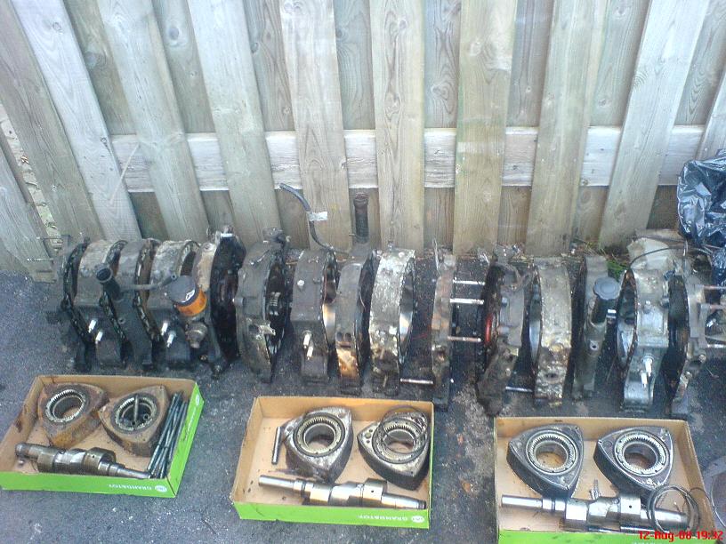
After I got the engines disassembled and got the majority of the gunk off them, I put them in cardboard boxes and brought them in the house. I also brought in all the rotors and seals and spent the evening cleaning and organizing. Here's how it ended up:
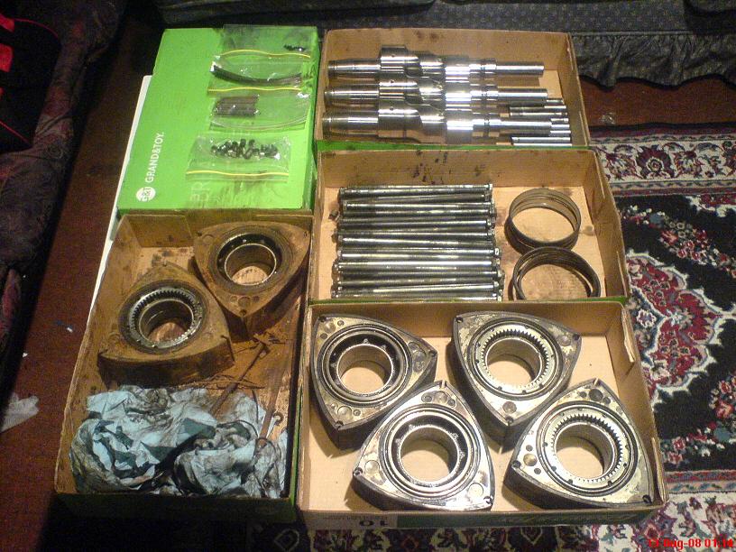
and all the seals I could salvage (I broke a few corner seals and left almost all the seals in the rusted rotors) got a basic cleaning and went into baggies
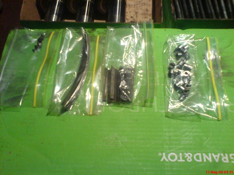
I used my digital vernier caliper to measure the apex seals. According to the FSM they're 8.5mm tall when they're new, and the limit is 7.5. The largest seal I have is barely 7mm tall. That's definitely not good.
So in summary, I got two good sets of rotors, at least one good set of irons, at least one e-shaft and absolutely no rotor housings or apex seals.
Not the best, but it could have been worse.
I'll post updated pics once the final cleaning/painting is done on the housings I have.
Jon
After I got the engines disassembled and got the majority of the gunk off them, I put them in cardboard boxes and brought them in the house. I also brought in all the rotors and seals and spent the evening cleaning and organizing. Here's how it ended up:
and all the seals I could salvage (I broke a few corner seals and left almost all the seals in the rusted rotors) got a basic cleaning and went into baggies
I used my digital vernier caliper to measure the apex seals. According to the FSM they're 8.5mm tall when they're new, and the limit is 7.5. The largest seal I have is barely 7mm tall. That's definitely not good.
So in summary, I got two good sets of rotors, at least one good set of irons, at least one e-shaft and absolutely no rotor housings or apex seals.
Not the best, but it could have been worse.
I'll post updated pics once the final cleaning/painting is done on the housings I have.
Jon
Trending Topics
Thread Starter
Joined: May 2002
Posts: 5,972
Likes: 37
From: Ottawa, Soviet Canuckistan
For those who were curious about measuring and inspecting parts to check clearances, the best guide is the shop manual. In this case I have cut *many* corners for this build and I'm aware of what the consequences will most likely be. The idea of this project was to get it up and running as cheaply as possible as a temporary measure for my Friend. As such, I'm not going to get my hands on the step-wear measuring device, the corner seal slot clearance tool, or most of the other tools needed to properly inspect the parts as per the FSM for this build. On my "Ultimate Streetable 12a" that I eventually plan to build this kind of measurement will be paramount, but for this build "the best of the worst" will have to suffice.
If anybody has any "throw away" apex seals or rotor housings that they were going to toss which are better than what I've got, let me know.
If anybody has any "throw away" apex seals or rotor housings that they were going to toss which are better than what I've got, let me know.
hey man, well first off, i'd seen your threads for a while and i just kept reading Keiko project such and such and finally today i was like, well wtf is up with this thread why is it so long, so i read from the first one til this one....wow....i'm amazed, it's an awesome story, well i don't have anything i could give you, but hopefully i can cheer for you lol. anyways keep it up,  i'm sure he's gonna love it. ...i'm interested to see the final outcome of this beast.
i'm sure he's gonna love it. ...i'm interested to see the final outcome of this beast.
Thread Starter
Joined: May 2002
Posts: 5,972
Likes: 37
From: Ottawa, Soviet Canuckistan
I figured you guys would like to see the collection of Apex Seals that came from these engines.
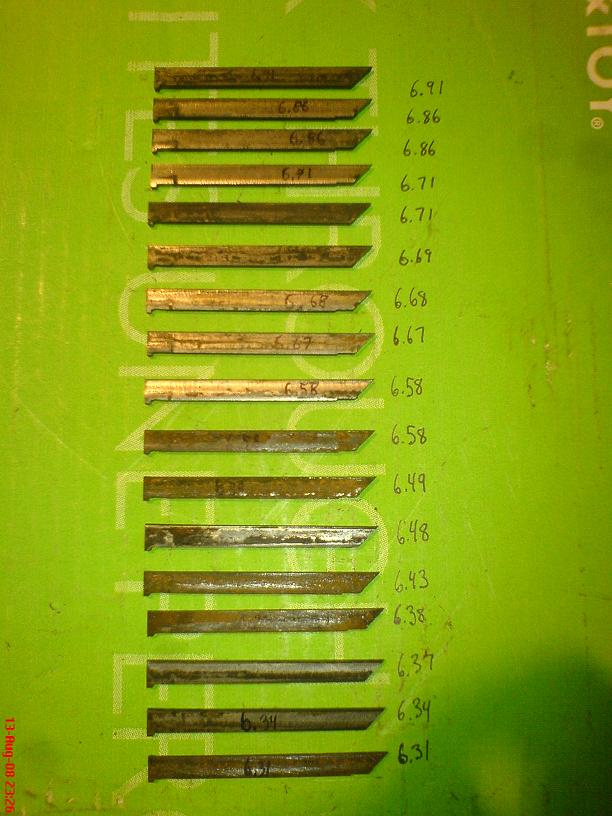
Remember, according to the FSM stock seals are 8.5mm and the wear limit before a rebuild is supposed to be 7.5mm
As it is, if I build the engine I'll have to use :
Front Rotor:
6.91mm
6.86mm
6.86mm
Rear Rotor:
6.71mm
6.71mm
6.69mm
I have no doubt the engine will *run* with apex seals that small, but how long and how well it will run is another question. Especially considering the state of the rotor housings I have, if you combine chrome flaked rotor housings with half-a-centimetre-under-spec apex seals you're not aiming to win any performance trophies with this engine.
I will take a second to say that *THIS* is exactly why I don't advocate throwing a turbo or supercharger on an engine that hasn't been newly rebuilt. You have to figure that these engines looked fine and one of them even ran and drove a car before I took them apart. The N/A 12a has gotten a reputation for being "bulletproof" because they'll run way under spec for a very long time as long as the OMP is working. If someone figured "my engine pulls strong, I'll just toss a turbo on it" they're just asking for that engine to finally break.
You don't know what your engine looks like inside until you actually *look* inside it. These engines held quite a few surprises, but I partially expected this kind of outcome considering one engine had been sitting in someone's yard for 2+ years and another one came out of a car with over 210,000km on it
Jon
I agree
I just cleaned up an engine with:
- pitting so severe, there were no wall supporting the coolant seals
- half a side seal was gone, and also was the corner seal
- both rotor housings had severe chrome flaking.
still, the engine was running until it was cracked open
I just cleaned up an engine with:
- pitting so severe, there were no wall supporting the coolant seals
- half a side seal was gone, and also was the corner seal
- both rotor housings had severe chrome flaking.
still, the engine was running until it was cracked open
Very good primer Jon. For the rusted housings, try a scotchbrite pad with CLR and rubber gloves. I've actually bead blasted housing surfaces, very gently, use glass beads/walnut shells or plastic beads, low pressure, to clean up the chrome.
Thread Starter
Joined: May 2002
Posts: 5,972
Likes: 37
From: Ottawa, Soviet Canuckistan
Jon
3M makes sanding pads, rust colored is about 400 grit, gray 600 and I recently heard of a gold. Haven't seen that one yet nor the grit spec on it. These pads work better than similar grit sandpaper and get into places you can't get to with stiff paper.
Thread Starter
Joined: May 2002
Posts: 5,972
Likes: 37
From: Ottawa, Soviet Canuckistan
It was a rust coloured 3M sanding pad in fact and the degreaser was just some generic store-brand Engine degreaser sold in 4L bottles. I'll snap a picture of both when I get a chance, since I'm going to pick up more degreaser and still have some of the sanding pad left.
Here's that Part 6 thread that I was mentioning where you can see how well the rotor housings from the rusted-to-hell motor turned out:
https://www.rx7club.com/showthread.php?t=781674
Jon
Here's that Part 6 thread that I was mentioning where you can see how well the rotor housings from the rusted-to-hell motor turned out:
https://www.rx7club.com/showthread.php?t=781674
Jon