
Mannykillers/ AAPARKAH Street/time Attack/Drift Build (heavy Pics) #Thisisthewolf

1" tubing has approximately 44% smaller (almost half) cross sectional area than the 1.5" tubing. I think that is a significant difference. Just my thoughts.
Also, you may want to re-design your filler neck. I see it is similar in design to mine and I have trouble with coolant being pushed out of the filler neck under high RPM causing low coolant. I will be changing the design of mine this winter. This may be alleviated if you run a low pressure cap in the system though.
Last edited by RENESISFD; Oct 16, 2012 at 06:20 PM.

How do you know?
1" tubing has approximately 44% smaller (almost half) cross sectional area than the 1.5" tubing. I think that is a significant difference. Just my thoughts.
Also, you may want to re-design your filler neck. I see it is similar in design to mine and I have trouble with coolant being pushed out of the filler neck under high RPM causing low coolant. I will be changing the design of mine this winter. This may be alleviated if you run a low pressure cap in the system though.
2. I think that 1' is used on alot of the cars that convert to electric water pumps. I would still keep an eye on it.
@Manny- I like the BJ welds... Bet they are stronger than JB weld.
Not picking or doing a debate on this -24 -16 etc.. just a informational for anyone info..
Great work on the ride MannyK you sure are much further on your ride than i am..
 ...
...

Yeah -16 is fine. It's what I've got, and I've personally seen two others make over 600whp with almost too cold coolant temps in the summer on a dyno (for at least 2 hours of tuning and playing around).

The hose might be -24 but the ID on OEM water pump housing inlet/outlet is larger than a -16 hose size but much smaller than -20.. Ether way -16 will work and be perfect.
Not picking or doing a debate on this -24 -16 etc.. just a informational for anyone info..
Great work on the ride MannyK you sure are much further on your ride than i am.....
Not picking or doing a debate on this -24 -16 etc.. just a informational for anyone info..
Great work on the ride MannyK you sure are much further on your ride than i am..
...
Update:
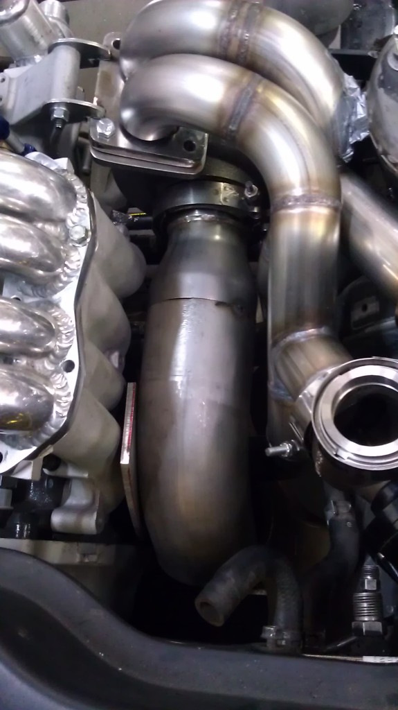
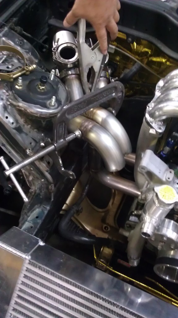
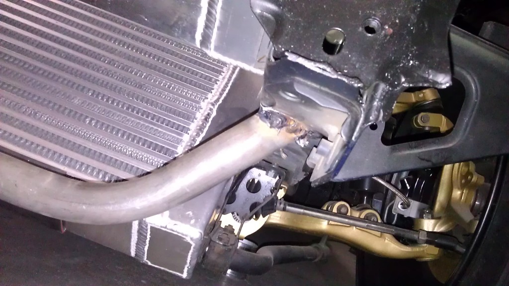
So here's a pic of the clearance between the runner and the strut tower. Looks like i have alittle under a half inch. I'm thinking I should be fine.
But once we got the clearance all figured out we figured we might as well get the down pipe all mocked-up as well. Wouldn't want to run into any clearance issues once we get everything all welded up. So bj tacked the Down-pipe to the new 3"to 4" V-band adapter while me and johhny worked on stitch welding the Rear fenders up.
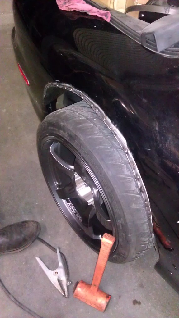
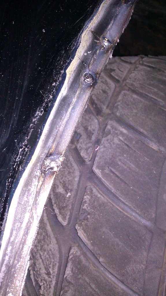
We'll use silicone to seal them up completely but this way there isn't sheet metal missing from the inside of the wheel wells. Still contemplating running the origin-lab rear overs. Still trying to make up my mind.. we'll see.
Got the turbo clocked and tacked it in place again with the mounts. Still might need to move it but it's approching it's final resting place
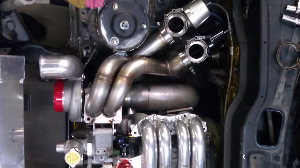
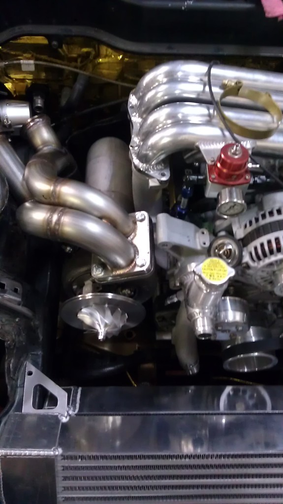
The down-pipe also has a little bit over a quarter of an inch of clearance on both sides. I'm definitely going to utilize some header wrap to try and control the heat. also deciding if I should go the inconel route or the white lightening ceramic coating for the header itself. I'll look into it a little more when I have time. Anyways... here's an overhead view of the set up and what we had to work with as far as clearance:
Also...I've decided that there needs to be some "aww" aspect for the car and I'm not the first or the last to do it. but yes the Wastegates will be routed up and out of the hood. I'm thinking if I can swing it and find a shape that fits both positions, i'll try to make 2 sets of pipes. One up and out of the hood and other other ones to dump under the car.
So wheel wells are almost complete just need to tack in the rear inner sections and then use silicone to seal up the rest.
I'm going to go see if I can get a 3" alum 90 for the turbo side into the IC today after work. Hopefully I can find something. i get most of the stuff at a scrap place...and they usually always have stuff. More updates later on tonight or tomorrow.
So here's a pic of the clearance between the runner and the strut tower. Looks like i have alittle under a half inch. I'm thinking I should be fine.
But once we got the clearance all figured out we figured we might as well get the down pipe all mocked-up as well. Wouldn't want to run into any clearance issues once we get everything all welded up. So bj tacked the Down-pipe to the new 3"to 4" V-band adapter while me and johhny worked on stitch welding the Rear fenders up.
We'll use silicone to seal them up completely but this way there isn't sheet metal missing from the inside of the wheel wells. Still contemplating running the origin-lab rear overs. Still trying to make up my mind.. we'll see.
Got the turbo clocked and tacked it in place again with the mounts. Still might need to move it but it's approching it's final resting place
The down-pipe also has a little bit over a quarter of an inch of clearance on both sides. I'm definitely going to utilize some header wrap to try and control the heat. also deciding if I should go the inconel route or the white lightening ceramic coating for the header itself. I'll look into it a little more when I have time. Anyways... here's an overhead view of the set up and what we had to work with as far as clearance:
Also...I've decided that there needs to be some "aww" aspect for the car and I'm not the first or the last to do it. but yes the Wastegates will be routed up and out of the hood. I'm thinking if I can swing it and find a shape that fits both positions, i'll try to make 2 sets of pipes. One up and out of the hood and other other ones to dump under the car.
So wheel wells are almost complete just need to tack in the rear inner sections and then use silicone to seal up the rest.
I'm going to go see if I can get a 3" alum 90 for the turbo side into the IC today after work. Hopefully I can find something. i get most of the stuff at a scrap place...and they usually always have stuff. More updates later on tonight or tomorrow.
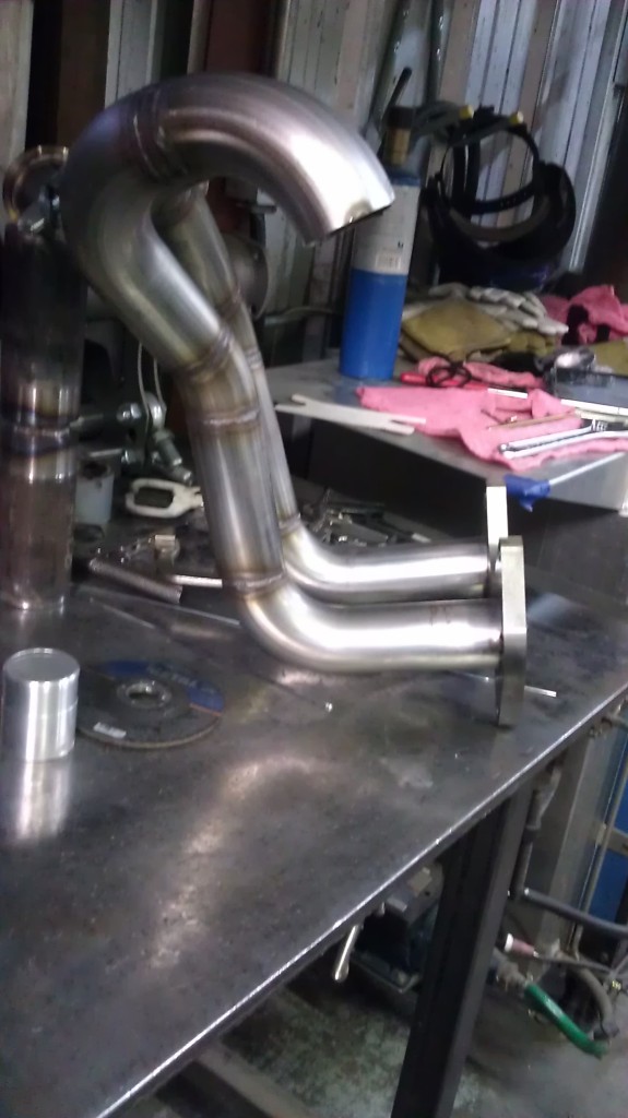
Well I got the 3" aluminum 90 from Aero-Bending in lancaster. you pay about 50 bucks and they take you in the back and you can pick out as many bends of whatever material you'd like from their scrap piles. They have a lot of bends... But it was a little difficult finding a 3" 90. But I got a few extras as well. Anyways..
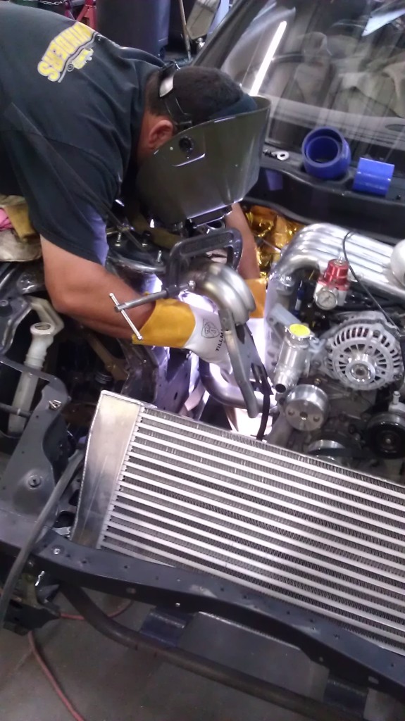
We started out our little session by tacking together the Runners in the exact position we wanted.
Bj doing work
While Bj tacked the runners to the motor flange Johnny started putting silicone on the tacked rear fenders to seal them up, and I started cleaning the dirty alum 90's so we could mock up the turbo charge tube that goes into the IC.
Forgot to take a pic of how we clocked the turbo a few more degrees counter clockwise so that we had just a little better entrance into the IC and it opened up some room for an Intake as well.
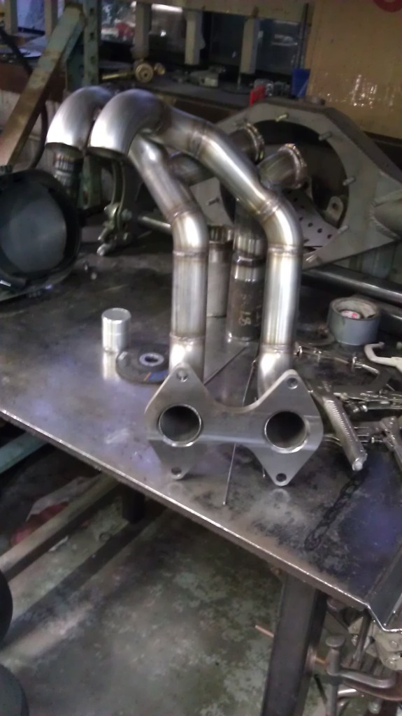
Next, BJ got the Motor flange welded onto the runners. Put the manifold on one more time to make sure that everything was where we wanted to... and Bingo. Downpipe sits a little over a quarter of an inch away from the LIM, which will get some heat barrier treatment, and the DP will be wrapped as well. The runners clear the Strut tower now with just under an inch of clearance which is a bit of a reliefe because the last thing I want is some annoying rattling or rubbing issue that could potentially crack the manifold in the event of impact.
Anyways... Bj ran out of weld rod so he wasn't able to fully weld the turbo flange on completely but here she is in all her glory.
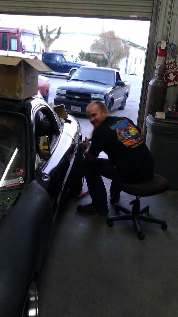
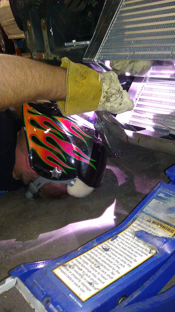
Johnny got under the front end and finished welding the Radiator support bar.
We started out our little session by tacking together the Runners in the exact position we wanted.
Bj doing work
While Bj tacked the runners to the motor flange Johnny started putting silicone on the tacked rear fenders to seal them up, and I started cleaning the dirty alum 90's so we could mock up the turbo charge tube that goes into the IC.
Forgot to take a pic of how we clocked the turbo a few more degrees counter clockwise so that we had just a little better entrance into the IC and it opened up some room for an Intake as well.
Next, BJ got the Motor flange welded onto the runners. Put the manifold on one more time to make sure that everything was where we wanted to... and Bingo. Downpipe sits a little over a quarter of an inch away from the LIM, which will get some heat barrier treatment, and the DP will be wrapped as well. The runners clear the Strut tower now with just under an inch of clearance which is a bit of a reliefe because the last thing I want is some annoying rattling or rubbing issue that could potentially crack the manifold in the event of impact.
Anyways... Bj ran out of weld rod so he wasn't able to fully weld the turbo flange on completely but here she is in all her glory.
Johnny got under the front end and finished welding the Radiator support bar.
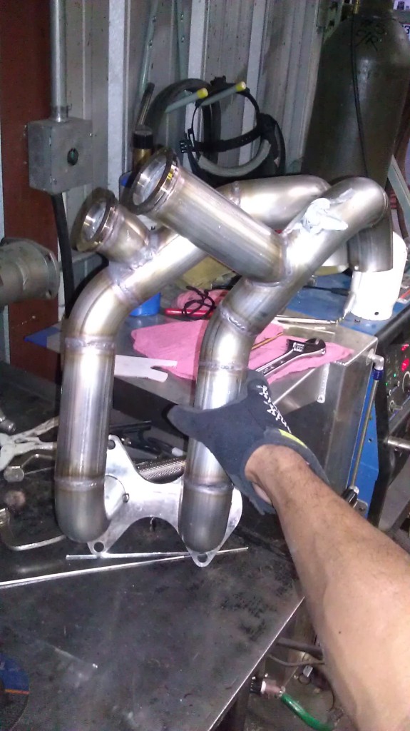
And finally the turbo manifold supports the turbo on it's own. We trashed the brace we had for the turbo because it was ugly.... so we're going to make another one that should come out stronger and much more visually appealing.
And how we left off for the night.
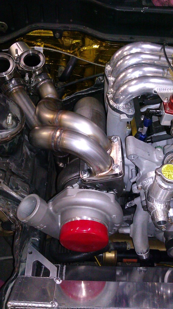
The downpipe fits..but were thinking we may want a little more clearance for the downpipe so we may cut it and take a small pie cut out of it to kick it to the left and away from the LIM. Still a lot to do but i'm happy with the progress over the past few days. Still need to order my PBM modded Drift Knuckles, figure out what i'm doing with my rear over fenders, order a quick release and adapter. Probly just run the NRG 2.5 and any short hub. Still need to make a little plate to mount my cannon plug for my rywire Mil spec harness. And I still need to order the AEM marine coils and harness from C. Ludwig. Don't want to mess with ignition amps anymore, and after talking to a few different people using them i've decided that is the route i'll be going. Once the hard mechanical set up is complete, I still need to pull the whole thing out for final Cleaning/Sealing/engine bay paint, and to install my new Clip ring for the exedy pressure plate. I need to order my side skirts as well.....and i've decided I don't want to run the Burnout front bumper anymore. If anyone has any whereabouts of a genuine or knock-off vertex front bumper....please let me know. I want it. Anyways.... More updates soon!
And how we left off for the night.
The downpipe fits..but were thinking we may want a little more clearance for the downpipe so we may cut it and take a small pie cut out of it to kick it to the left and away from the LIM. Still a lot to do but i'm happy with the progress over the past few days. Still need to order my PBM modded Drift Knuckles, figure out what i'm doing with my rear over fenders, order a quick release and adapter. Probly just run the NRG 2.5 and any short hub. Still need to make a little plate to mount my cannon plug for my rywire Mil spec harness. And I still need to order the AEM marine coils and harness from C. Ludwig. Don't want to mess with ignition amps anymore, and after talking to a few different people using them i've decided that is the route i'll be going. Once the hard mechanical set up is complete, I still need to pull the whole thing out for final Cleaning/Sealing/engine bay paint, and to install my new Clip ring for the exedy pressure plate. I need to order my side skirts as well.....and i've decided I don't want to run the Burnout front bumper anymore. If anyone has any whereabouts of a genuine or knock-off vertex front bumper....please let me know. I want it. Anyways.... More updates soon!

Ok you guys convinced me (re the coolant line size) .
.
It is nice to see so much progress in such a short amount of time.
Re: the turbo brace, Perhaps you should cut off the cast air pump bracket and weld a different support point there . I just think the cast piece clashes with all of the other custom stuff in that engine bay.
Are you back purging the manifold when you are welding? What do you plan to do to get all of the weld slag off of the inside if you did not. When my manifold was made I had noticed a ton of loose slag in the manifold that I ground off.
Also, I think you should cut the 3-4" transition right at the start of the transition inorder to continue the 15 degree taper out of the turbo.
I really like how your radiator mounts came out.
And if you have not seen this I will leave this here as I thought it was very informative. When it comes to routing your turbo coolant lines.http://www.turbobygarrett.com/turbob...er_Cooling.pdf
It is nice to see so much progress in such a short amount of time.
Re: the turbo brace, Perhaps you should cut off the cast air pump bracket and weld a different support point there
. I just think the cast piece clashes with all of the other custom stuff in that engine bay.Are you back purging the manifold when you are welding? What do you plan to do to get all of the weld slag off of the inside if you did not. When my manifold was made I had noticed a ton of loose slag in the manifold that I ground off.
Also, I think you should cut the 3-4" transition right at the start of the transition inorder to continue the 15 degree taper out of the turbo.
I really like how your radiator mounts came out.
And if you have not seen this I will leave this here as I thought it was very informative. When it comes to routing your turbo coolant lines.http://www.turbobygarrett.com/turbob...er_Cooling.pdf
Ok you guys convinced me (re the coolant line size).
It is nice to see so much progress in such a short amount of time.
Re: the turbo brace, Perhaps you should cut off the cast air pump bracket and weld a different support point there. I just think the cast piece clashes with all of the other custom stuff in that engine bay.
Are you back purging the manifold when you are welding? What do you plan to do to get all of the weld slag off of the inside if you did not. When my manifold was made I had noticed a ton of loose slag in the manifold that I ground off.
Also, I think you should cut the 3-4" transition right at the start of the transition inorder to continue the 15 degree taper out of the turbo.
I really like how your radiator mounts came out.
And if you have not seen this I will leave this here as I thought it was very informative. When it comes to routing your turbo coolant lines.http://www.turbobygarrett.com/turbob...er_Cooling.pdf
It is nice to see so much progress in such a short amount of time.
Re: the turbo brace, Perhaps you should cut off the cast air pump bracket and weld a different support point there
. I just think the cast piece clashes with all of the other custom stuff in that engine bay.Are you back purging the manifold when you are welding? What do you plan to do to get all of the weld slag off of the inside if you did not. When my manifold was made I had noticed a ton of loose slag in the manifold that I ground off.
Also, I think you should cut the 3-4" transition right at the start of the transition inorder to continue the 15 degree taper out of the turbo.
I really like how your radiator mounts came out.
And if you have not seen this I will leave this here as I thought it was very informative. When it comes to routing your turbo coolant lines.http://www.turbobygarrett.com/turbob...er_Cooling.pdf
The cast piece isn't visually appealing.... as most cast stuff tends to be. But it is the best place for the mount. It's right there....and we have a pretty good plan on how to make it work and not look so horrible haha. more pics when were done.
Are you saying keep the 3" all the way through to the IC? The pressure drop needs to be as close to the turbo as possible
The manifold has some sloppage on the inside..which will be blended in nicely with our porting grinder.
^ On the exhaust side (turbine outlet) you have the start of the transition a few inches away from the turbine outlet. I think you should shorten it so you basically weld the v-band flange at the start of the transition.
As far as the welding slag how are you going to reach into the manifold to the middle where you have some welded seams, or am I missing soemthing.
As far as the welding slag how are you going to reach into the manifold to the middle where you have some welded seams, or am I missing soemthing
.
^ On the exhaust side (turbine outlet) you have the start of the transition a few inches away from the turbine outlet. I think you should shorten it so you basically weld the v-band flange at the start of the transition.
As far as the welding slag how are you going to reach into the manifold to the middle where you have some welded seams, or am I missing soemthing.
As far as the welding slag how are you going to reach into the manifold to the middle where you have some welded seams, or am I missing soemthing
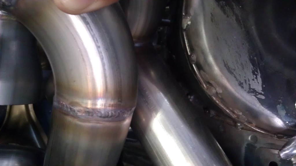
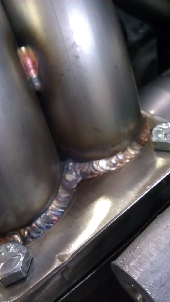
.The welds throughout the whole manifold are completely clean. The only slop we have is at the Motor flange and turbo flange. Everything else was smoothed during the process of welding each runner. If we left it all messy we would risk messing up our exhaust blade

Aaron, he is talking about the inside of the manifold. If the manifold is not back purged there is a chance of contaminants from the air causing a scale or oxidation inside the runners. This is what he keeps referring to, hope that helps.
ohh ok..... well in that case.. I really dont know if it was back purged or not. Bj is pretty experienced...so I wouldn't doubt if it was, but if it wasn't i'm sure there's a reason for it.. I'll ask him about it.
You might want to add some kind of dampening to the radiator mounts themselves. My buddy had his radiator hard mounted to his tube chassis on his tube front 350z and the first time he launched the car, the radiator cracked. IIRC it was a Fluidine so I know it wasn't because of lack of quality of the radiator.
Not to "troll" though right?
You might want to add some kind of dampening to the radiator mounts themselves. My buddy had his radiator hard mounted to his tube chassis on his tube front 350z and the first time he launched the car, the radiator cracked. IIRC it was a Fluidine so I know it wasn't because of lack of quality of the radiator.
We've actually left room for our mounts. The radiator support is welded to the frame but we are using rubber mounts for the radiator and the I/C
If he didn't back purge (which it looks like he didn't) or use solarflux, you ABSOLUTELY have sugar alllllll inside those runners. I'll guarantee it. Not so much of a big deal for post-turbo exhaust pieces (I'm OCD so I'll be back purging everything) but for pre turbo you're just asking for trouble. Granted, the sugars are strong and stick to the material well, but every bead is most likely lined with little grenades waiting to break off.
Not to "troll" though right?
Not to "troll" though right?
 Thanks much! Hows your Car coming? Get your Exhaust mani done yet?
No big updates. Made a stainless plate for my cannon plug for my engine wiring harness. And fully welded up my custom seat bracket. It sits nice and low but I used the side mount plates off the bride rails so it retains adjustability up and down. I'll be tilting it back a bit just for my preference but thats about all we got done yesterday. More Updates soon!