When you click on links to various merchants on this site and make a purchase, this can result in this site earning a commission. Affiliate programs and affiliations include, but are not limited to, the eBay Partner Network.
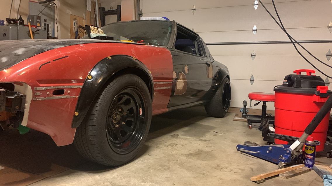
Refreshed my struts with new cartridges and RB lowering springs. My generic-application knockoff wheels have a different offset than factory so I rotated the strut tops 90 degrees to give me some negative camber, result is the tops don't stick out like a hot wheels. Holy god, fresh suspenders is nice! All my wibblewobble and clunks disappeared.
I had my cars original 12A sitting around for the last few years. I had pulled it out to swap it with a rebuilt streetproot 12A. Nothing wrong with motor when pulled, just wanted the streeport power. No hard starts, etc...
So I have read all about housing chrome issues with the pre 86 housings. I was probably over optimistic that my 60k Mile original 12A would be in decent shape.
Wrong!! Everything looks pretty good but housings are trashed much more than I was expecting. The engine is original to the car, which seemed to be well cared for, other than sitting for some time. Wondering how the housings got this bad?! Even the coolant passages look brand new...
Worst is right around the compression area.
My 12a looked like that after 180k original motor. I was surprised it still started and ran great. I was beating on it every day. It's is even more surprising after such low miles though.
Fixed some exhaust leaks with new Felpro and Beck/Arnley exhaust manifold gaskets. I also hit the manifold and heat shield with some sandpaper and VHT Flame Proof.
It actually sounds like a car now instead of a lawnmower. That allowed me to hear a vacuum leak which after reading this post, I found was the same problem, with a hole in the Anti-afterburn hose, hopefully once that shows up it'll take care of the rough idle.
Replaced intake manifold gasket and coolant seals.
Finished a Nikki clean-up. Mounted the carb with all external vacuum ports capped. Start and warmed the engine (12A with 124k miles). Adjusted the idle until it purrs at 850 rpm.
BTW - I found that an accelerator pump diaphragm from the 1982 Yamaha Vision XZ550R will fit the bolt/screw pattern of the Nikki. The stub shaft/plunger is a larger diameter so I just put the pump housing in the mill and bored it out a bit. The last few pump diaphragms I got with kits failed and started leaking in a few months so I am going with something that is better quality.
Also the great secret (probably already known) to removing the accelerator pump in-situ depends on what you do when reassembling the carb. Put the top two screws and the bottom right screw (the one obscured by the pump lever) in and tighten them. Leave the bottom left screw out. Reverse the pin and insert it into the pump lever and housing. Put the e-clip put on the other end, now to the right side, to hold it. Now put in the last screw. Now if this new diaphragm fails perform the reverse steps to remove/replace the diaphragm without disassembly of any other part of the carb.
Last edited by injuhneer; 10-18-21 at 11:33 AM.
Reason: typo
Well the prototypes on the EFI abomination are nearly complete, just did another test fit today. Will it work? Honestly I don't know. I have way too much time (ahem, among other things) into this harebrained idea as it is...
Well the prototypes on the EFI abomination are nearly complete, just did another test fit today. Will it work? Honestly I don't know. I have way too much time (ahem, among other things) into this harebrained idea as it is...
I like it! Carbon fiber nylon printed? Put up more pics!
I like it! Carbon fiber nylon printed? Put up more pics!
Yeah, the final one will be carbon fiber nylon. I've actually already printed one "final" but we had a power outage overnight (it's a 47 hour print) and I didn't clear the molten blob on the print resume fast enough, so it crashed and caused a major layer shift. Conveniently that one wouldn't have worked anyway as I had not anticipated the coolant temp sensor being in the way of the throttle cable. What will hopefully be the final prototype is printing as I type this, and then I'll print the cf-nylon version once a new roll of filament arrives (I can only get 1.8 or so prints of the final cf-nylon version per roll, so I really don't want this one to mess up, again...).
While I don't have many other photos of the TBI adapter at the moment, I have also 3D printed the CAS bracket, again out of cf-nylon. The first photo is the final PETG prototype loosely installed on the engine, and the second is the final cf-nylon print ready to go. Below those is a photo of the messed up cf-nylon print showing how the original angle of the throttle cable bracket will collide with the coolant temp sensor.
I'll better detail the whole project in my build thread once I get a little further along. We're still in the very early stages here.
I like it! Carbon fiber nylon printed? Put up more pics!
That's fantastic man! I love it.
I had the same issue with the coolant sensor when I went ITB. Post up your build thread link.
Are the injectors going to sit on the printed part or is the printed part only an adaptor for a 4 barrel TBI?
That's fantastic man! I love it.
I had the same issue with the coolant sensor when I went ITB. Post up your build thread link.
Are the injectors going to sit on the printed part or is the printed part only an adaptor for a 4 barrel TBI?
Haha, glad to hear you don't think I'm completely nuts . The build thread is here: The Unlikely Daily - Stardust Blue 1980 GS. I'll put in it my sig one of these days. I don't update it too often, but it's where I'll post anything that doesn't deserve a full thread dedicated to it.
The injectors will sit in the printed body. You can sort of see one of the injectors sitting on the drivers side as a mock up in the cf-nylon photo (I was making sure the fuel rail and lines will not collide with the temp sensor either). There's four injectors each at a 45 degree angle as I couldn't get them much more parallel to the airflow due to space limitations. It uses standard Bosch EV14 style injectors and they are fitted into the main printed "adapter" using some 1/2JZ fuel injector bungs that will be epoxied into the printed adapter. The OMP (because I'm OMP crazy I guess) will dump oil directly below the primary injectors so that it can hopefully mix well and be carried away into the engine effectively.
All the rest of the parts were chosen based on easy availability. The throttle body is a 70mm Honda unit with a Honda TPS and [modified] MAP sensor. The IACV is also a Honda unit and the temp sensor is from ~2002-2018 Nissans. I don't want to go into too much detail here since it'll just get lost in the abyss of this massive thread, so perhaps I'll go write a little update in my build thread soon here.
EDIT: I just looked at my build thread and I guess I already detailed the basic idea of what all I'm doing. Post #11 is where the meat of things are, and since I haven't really made too many giant leaps forward I'm going to hold off on another built thread update until I have some more stuff to share.
Last edited by Benjamin4456; 10-20-21 at 02:54 PM.
Haha, glad to hear you don't think I'm completely nuts . The build thread is here: The Unlikely Daily - Stardust Blue 1980 GS. I'll put in it my sig one of these days. I don't update it too often, but it's where I'll post anything that doesn't deserve a full thread dedicated to it.
The injectors will sit in the printed body. You can sort of see one of the injectors sitting on the drivers side as a mock up in the cf-nylon photo (I was making sure the fuel rail and lines will not collide with the temp sensor either). There's four injectors each at a 45 degree angle as I couldn't get them much more parallel to the airflow due to space limitations. It uses standard Bosch EV14 style injectors and they are fitted into the main printed "adapter" using some 1/2JZ fuel injector bungs that will be epoxied into the printed adapter. The OMP (because I'm OMP crazy I guess) will dump oil directly below the primary injectors so that it can hopefully mix well and be carried away into the engine effectively.
All the rest of the parts were chosen based on easy availability. The throttle body is a 70mm Honda unit with a Honda TPS and [modified] MAP sensor. The IACV is also a Honda unit and the temp sensor is from ~2002-2018 Nissans. I don't want to go into too much detail here since it'll just get lost in the abyss of this massive thread, so perhaps I'll go write a little update in my build thread soon here.
EDIT: I just looked at my build thread and I guess I already detailed the basic idea of what all I'm doing. Post #11 is where the meat of things are, and since I haven't really made too many giant leaps forward I'm going to hold off on another built thread update until I have some more stuff to share.
Awesome man! Keep us posted. Love seeing this stuff. I need to upgrade to an all metal hot end and start making some parts for the FB.
I'm always a fan of DIY solutions. I've got all sorts of ideas foe putting EFI on several things, but have yet to actually do anything DIY. I'm cheating on my SA22C by using GSL-SE stuff (at least initially.)
I cleaned, painted and installed the front sway bar .. ...when I took out the front end for rebuild I put the sway bar away and I lost sight of it.....😂
But now is clean and painted and back on the car....
Wow, swapping out the sway bar was a MAJOR PITA for me. You need to drop at least one of the front mounting brackets to fish it through (WAY tougher than any other car I've replaced them on). Congrats.
Wow, swapping out the sway bar was a MAJOR PITA for me. You need to drop at least one of the front mounting brackets to fish it through (WAY tougher than any other car I've replaced them on). Congrats.
Thanks.....and yes it was a PITA....but I had it all out anyway because I'll cleaned it and painted everything so it was a little easier......
 10-07-21, 03:51 PM


 . The build thread is here: The Unlikely Daily - Stardust Blue 1980 GS. I'll put in it my sig one of these days. I don't update it too often, but it's where I'll post anything that doesn't deserve a full thread dedicated to it.