Project OldTree: The 12 Days of Rotormas
 11-13-11, 10:28 AM
#176
I would not compare those to our brackets. The single gusset design with the mounting hole in the opposite corner is going to put a lot of strain on those welds. Our dual gusset design with press brake formed body does not stress the welds since it is a continuous piece of metal across the bottom. Additionally, ours have the motor mount holes closer to the center which mean there is no leverage on the gusset welds when supporting the weight of the engine.
 11-13-11, 11:03 AM
#177
I am not saying that your brackets will not work, just that they are apples and oranges when compared to ours. Your brackets are relying heavily on the strength of the welds. Where as ours are designed to utilize the strength of the steel.
11-14-11, 06:44 PM
#178
Duly noted Banzai, no harm done. Unlike some people, I appreciate constructive criticism as you've put forth. Another triangle brace is going to be added to stiffen the structure up as you suggested.
On a more fun note, LIM is on, Exhaust manifold is on, Turbos & Sequential Actuator are fitted. In doing so, Lynn & I found another fault due to an oversight on my part and general incompetence on a previous owner. Not sure who did it, but whoever did gets a rating of "complete fucknut" from the master.
The rear rotor housing had one exhaust manifold stud MUCH shorter than the rest, and torqued in so much that it took being heated up to glowing orange, PB blaster and BOTH of us to extract it. 2 hours later, threads were cleaned up and the manifold was on & torqued to spec.
Drool time:

Also started on some secret stuff, more to be revealed when it's ready.
On a more fun note, LIM is on, Exhaust manifold is on, Turbos & Sequential Actuator are fitted. In doing so, Lynn & I found another fault due to an oversight on my part and general incompetence on a previous owner. Not sure who did it, but whoever did gets a rating of "complete fucknut" from the master.
The rear rotor housing had one exhaust manifold stud MUCH shorter than the rest, and torqued in so much that it took being heated up to glowing orange, PB blaster and BOTH of us to extract it. 2 hours later, threads were cleaned up and the manifold was on & torqued to spec.
Drool time:
Also started on some secret stuff, more to be revealed when it's ready.
11-18-11, 06:48 PM
#179
Looks like the coolant return Y-pipe has vanished between here and the shop. Thanks to me buying a second set of turbos last year for the downpipe, the master and I turned the spare, mangled feed Y-pipe into a custom AN6 return, routed under the UIM to the water pump housing's barb.
Cost: $0
Per Banzai Racing's suggestion, the mounting brackets are now reinforced and won't break no matter what.
Bought a Spectre #8707 intake adapter at Autozone yesterday and put it on the front turbo inlet. It fit perfectly fine, despite needing #9714 to plumb the Blowoff Valve back in, it being made of plastic didn't sit well on my conscience. Might be fine on a civic, but not a turbo rotary, much less a twin turbo, and even moreso a 20B Twin Turbo So today we made an all steel version using some spare 2.5" intake tubing and a 1/2" NPT pipe nipple modified into a 12AN hose barb.
Cost: $1
Ignition coil brackets are being redone from the ghetto ones I did in the spring. Still going to be under the UIM, but mounted sideways. Best of all, it means plug wires can be regular LS2 ones
Cost: $0
Reinstall is scheduled for tomorrow after the coils are mounted, pics shall follow.
Cost: $0
Per Banzai Racing's suggestion, the mounting brackets are now reinforced and won't break no matter what.
Bought a Spectre #8707 intake adapter at Autozone yesterday and put it on the front turbo inlet. It fit perfectly fine, despite needing #9714 to plumb the Blowoff Valve back in, it being made of plastic didn't sit well on my conscience. Might be fine on a civic, but not a turbo rotary, much less a twin turbo, and even moreso a 20B Twin Turbo
So today we made an all steel version using some spare 2.5" intake tubing and a 1/2" NPT pipe nipple modified into a 12AN hose barb.Cost: $1
Ignition coil brackets are being redone from the ghetto ones I did in the spring. Still going to be under the UIM, but mounted sideways. Best of all, it means plug wires can be regular LS2 ones
Cost: $0
Reinstall is scheduled for tomorrow after the coils are mounted, pics shall follow.
11-19-11, 08:42 PM
#180
The past few days have been spent on making the perfect coil mounts and constructing a perfect vacuum system for the twin turbos. Engine is still on the bench till tomorrow. But for now, here's a couple teaser pics. You'll have to excuse the mess as the first pic is a mockup using vinyl tubing. Free bump for Menards having very inexpensive 0.170 and 0.250" vinyl tubing. Yes I know 0.170 isn't exactly correct for the smaller 5mm lines, but it's fine for doing a mockup.

These are regular LS2 Truck spark plug wires, $28.99 at Oreilly's. The coils are now in their final home, on completely hand-fabricated stainless steel brackets, placing each rotor's coils in one tidy package. Start drooling now...

Completed ignition & vacuum system are coming soon...
These are regular LS2 Truck spark plug wires, $28.99 at Oreilly's. The coils are now in their final home, on completely hand-fabricated stainless steel brackets, placing each rotor's coils in one tidy package. Start drooling now...
Completed ignition & vacuum system are coming soon...
11-20-11, 05:42 PM
#181
Intake is done, Y-pipe installed, coils are mounted, so the engine is ready for reinstall. By sheer luck, the Power Steering pulley boss finally came off thanks to several soakings over the past few months with PB Blaster and a 3-jaw bearing puller.
Obligatory picture:

Once the engine is in, then comes the cooling frame, finishing the water pump housing, mounting & plumbing all of the heat exchangers and then doing the exhaust. Gonna be using all the 'hacks' I know of to get the car done on time, within budget and done correctly.
Obligatory picture:
Once the engine is in, then comes the cooling frame, finishing the water pump housing, mounting & plumbing all of the heat exchangers and then doing the exhaust. Gonna be using all the 'hacks' I know of to get the car done on time, within budget and done correctly.
11-21-11, 07:26 PM
#182
At long last, the engine is back in its home. Took 5 hours to get it mated up correctly to the transmission and installed. Something I want to mention here is that clutch disc alignment tools from the parts store are GARBAGE. I have one, lined up the clutch with it and we couldn't get the transmission on all the way because of the sloppiness in the tool. Even pushing & wiggling it with all my strength wouldn't budge it the last 1/8". Surprisingly, there was no damage to anything from the misalignment. So Lynn aligned the clutch by eye as I put the pressure plate on and the transmission nearly installed itself. Not sure if an alignment tool from Mazda would be better, but an extra input shaft is definitely the way to go from now on.
One important point I want to mention is that when doing a 20B conversion: Having installed the same engine & transmission both ways, together and separately, I can now say with absolute certainty that it can be done either way, but doing so separately is MUCH easier and requires only two people, whereas installing them together requires three.
Installing them together took Lynn and my buddy Matt wiggling the engine & crane while I was under the car working the transmission & engine mount bushings. Took us about an hour, due to the engine mount bushings being a major PITA when combined with lining up the transmission crossmember.
Driver's side:

Passenger side:

And the guys that made it all possible:

One important point I want to mention is that when doing a 20B conversion: Having installed the same engine & transmission both ways, together and separately, I can now say with absolute certainty that it can be done either way, but doing so separately is MUCH easier and requires only two people, whereas installing them together requires three.
Installing them together took Lynn and my buddy Matt wiggling the engine & crane while I was under the car working the transmission & engine mount bushings. Took us about an hour, due to the engine mount bushings being a major PITA when combined with lining up the transmission crossmember.
Driver's side:
Passenger side:
And the guys that made it all possible:
11-22-11, 07:31 PM
#183
Lynn got his welding groove back, so the water pump housing is finished. And I attacked the vacuum lines with a fury like no other. Power Steering pump is back on, clutch hydraulics back in place now.
Vacuum system: 85% done
Power Steering: 80% done
Water Pump: FINISHED & ready for install

Tomorrow's agenda is to bleed the clutch, get the radiator & water pump in place, bolt the driveshaft in and make the downpipe. Gonna be a LONG day.
Vacuum system: 85% done
Power Steering: 80% done
Water Pump: FINISHED & ready for install
Tomorrow's agenda is to bleed the clutch, get the radiator & water pump in place, bolt the driveshaft in and make the downpipe. Gonna be a LONG day.
11-23-11, 07:01 PM
#184
Today was spent on fabrication, topside finishing work & the vacuum system. UIM & throttle body are on, fuel supply and return & heater feed hoses are all connected.
PREPARE TO **** BRICKS...
The completed vacuum system. 7 solenoids total, including my custom Boost Creep Defender System. Should the car try to overboost past 10psi, the system opens the BOV as soon as it hits 14psi, courtesy of a MAP switch in the haltech. BCDS is the clear hoses here, will do them in silicone tomorrow

First half of the new Intake Elbow. All TIG, 4043 filler rod for every bead and only using the stock 20B Cosmo intake elbow as material. Lynn is THE ****!

PREPARE TO **** BRICKS...
The completed vacuum system. 7 solenoids total, including my custom Boost Creep Defender System. Should the car try to overboost past 10psi, the system opens the BOV as soon as it hits 14psi, courtesy of a MAP switch in the haltech. BCDS is the clear hoses here, will do them in silicone tomorrow
First half of the new Intake Elbow. All TIG, 4043 filler rod for every bead and only using the stock 20B Cosmo intake elbow as material. Lynn is THE ****!
 11-23-11, 09:33 PM
#188
Beefhole, there is a perfectly logical reason to having 7 solenoids. It takes 6 to operate the turbos sequentially using the simplified sequential diagram. It's just like the FD, but has a differently shaped Y-pipe. Each of these has one solenoid on it:
Turbo Pre-Control Actuator
Wastegate Actuator
Turbo Control Actuator (Boost Port)
Turbo Control Actuator (Vacuum Port)
Charge Control Valve
Charge Relief Valve
The last solenoid is connected to the Blowoff Valve. Normally a Blowoff Valve is opened by vacuum from the intake manifold. My system uses two sources of vacuum, the intake manifold and the front turbo inlet and a solenoid to switch between them, activated by the haltech at 14psi.
Under normal operation, the blowoff valve opens when shifting up (Manifold under vacuum triggers the BOV), just like any other turbo car. But in the case of Boost Creep (Turbo FCs & FD get this with a freer flowing exhaust), the haltech will leave it alone till it creeps up to 14psi. That is when it triggers Solenoid #7, switching the BOV's source from the intake manifold to the front turbo inlet (constant vacuum source), which makes it instantly dump ALL boost untill it drops below 14psi again.
The result: Boost Creep is limited to 4psi beyond the wastegate's opening pressure (10psi), the turbos are kept within safe operating limits and crazy lean conditions (AKA blown engine from Boost Creep) can't happen. So in the case that the changeover system malfunctions from a solenoid crapping out, the BOV can be activated by the haltech to make sure the engine will keep going without damage.
Not too shabby for being bored over the summer.
Okay, now for all the fittings. The reason for this is that anyone with a turbo rotary has had solenoid nipples break off, or the nipple on a very important device like the Charge Relief Valve or BOV break. My BOV came with a broken nipple, through no fault of the seller. The fittings on each line are there so each connection can be taken apart without stressing and risking breaking devices that are so critical to the car's operation. Got the idea from the 3rd Gen section about using aquarium brass tees for the turbos and took it a step further. Brass fittings can take much more heat, wear & tear than a plastic nipple could hope to.
Jaggermouth, the welds on the intake elbow have NOT been ground down yet, the picture was taken right after it was cool enough to handle.
Right now, everything is just mocked up and will be cleaned up later once the car is up & running correctly. Maybe in the spring I'll get motivated to make a nice stainless steel bulkhead partition and mount all of the fittings on there. Not only will it keep the solenoids from ever crapping out from the heat, but it'll also provide a nice, clean interface for each connection.
First, make it work. Then make it pretty.
11-24-11, 06:45 AM
#189
Does the haltech you are using have an overboost feature? I imagine higher end standlones would have an option to cut fuel if boost exceeds a predetermined level. Seems like you are using the BOV as a pop-off valve, I've thought of that myself but my older E6k cannot control something like that.
As for the stock twins and 6 solenoids... YIKES!
As for the stock twins and 6 solenoids... YIKES!
11-24-11, 07:17 AM
#190
Not sure if the PS2K can cut fuel on overboost, but that sounds like good intentions ending up as a recipe for disaster. With boost creep comes running lean. Cut the fuel and it would go from "2008 Recession" lean to "Starving in Ethiopia" lean in an instant.
Much easier to just open the blowoff valve. It'll run a bit rich for a second or two, then get right back to normal as soon as boost pressure drops back to normal.
To reiterate, this is not a band-aid for poor tuning. This system is in case of unforeseen boost creep, despite tuning the car correctly. Tune the car correctly from the start, then have this system in case something acts up later such as the wastegate solenoid failing. So instead of getting the 1986 Challenger explosion, you get Apollo 13 and can get back home with zero boost thanks to a manual override switch wired parallel to the ECU output.
If you're interested, I can show you how to build it without using an extra ECU output.
The 20B twins operate exactly like the FD twins, the only difference between my setup and a stock FD's is solenoid location. FDs have them packed under the UIM, where they are well known to go belly-up. Can't recall who it was, but one person compiled all the vacuum device testing info in a single thread and showed that even NEW solenoids can fail immediately when baked in an oven to simulate being under the UIM. Needless to say, this was not going to work for my car. And because there's no airflow meter anymore, its M6x1.0 holes made the perfect spot to mount all of the solenoids, vacuum box & front inlet manifold with very little fabrication.
EDIT: Here's the thread I mentioned
https://www.rx7club.com/showthread.p...+control+valve
Last edited by Akagis_white_comet; 11-24-11 at 07:24 AM. Reason: added link to test procedure for solenoids & other vacuum parts
11-24-11, 08:52 AM
#191
fuel cut on over boost shouldn't blow a motor. The stock FC ECU does this (to the rear rotor). It cuts completely, it's not like it decides halfway through the pulse "oops, time to cut this fuel off!" It just won't fire the injectors. NO fuel means no combustion. This could also be done with ignition cut (machine gun noises).
Anyway... another good thing to do is use the 2 or even 3 bar map sensor. Even if you don't plan on going more than 10PSI, you still will have a map for any loads above that. I only run 15psi, but I have a map for 30psi. If I accidentally spike to 20psi, I am covered with a conservative fuel and ignition map, so I'm not terribly worried.
Ultimately, a pop off is still a good idea, I like your thinking.


 11-25-11, 02:00 PM
#195
Didn't get to the shop today, due to a tire on my mom's car choosing to split apart at the steel belts last night. But even without me, a small bit of progress still happened
The water pump is now on, so all that's left to build is the exhaust and cooling frame. After that is all hoses. Thanks to the clever little adapter the master put together yesterday, I can re-use the stock bottom radiator & heater hoses so the only flex hoses will be a 1.5" one for the radiator inlet and a 1.75" one to mate the radiator outlet to the custom tee. That'll save me at least $35.
The "dryer duct" is actually a piece of 2.25" ID stainless steel exhaust flex pipe from Autozone. For $7 it seemed like a clever way to plumb the intake without having to drag out the 20-ton pipe bender and screw around with trying to keep sand in a pipe while bending it. It'll be redone the correct way sometime later, but this will do to get the intercooler positioned and connected.
Exhaust will be tackled in the same manner. $15 for 6ft of 2.25" ID flex pipe (again, stainless), tack on two flanges and call it done for now. Both the intake & exhaust plumbing can be cloned using the flex models just by tacking a couple pieces of 1/8" flat steel on to brace it across each bend.
FWIW, flex pipe is great for prototyping any plumbing with. Sure, the bend radius is horribly big, evidenced by the intake piece only being able to do a 90 degree turn across the whole length, but it's cheap, is stainless steel (weldable) and allows for no-tool working in the same size as the final piece. And another bonus is that since it's stainless steel, it'll hold up under heat reasonably well while you're building the final hard pipe version.
On a side note, Lynn has a turbo for sale. It's from Rajay Industries in Long Beach, CA. Model# 3AB1883581 (I think, picture was a bit fuzzy on this), Serial# 0099969, Part# 600584-07. It's completely new, with absolutely ZERO SHAFT PLAY, never bolted up to anything EVER. Looks about the size of a Hitachi HT-18 give or take, so might be a bit small for a rotary. Probably a good fit for a KA24, SR20 or 4G63. Will get more details later. Once again, this turbo is BRAND NEW, NEVER USED. PM me if interested
 11-26-11, 06:32 PM
#197
Cooling cradle is 50% finished now, turbo oil supply line is done in braided SS now. The Cosmo downpipe is bolted up, resonator is on and awaiting the last exhaust section to mate them together. Hood was modified a bit more but now clears the Cosmo Y-pipe. Water pump upper neck is now a tad shorter and exits straight forward.
Front of the engine is nearly done now. Just need to flip the hangar bracket to the back of its mounting ear so it won't interfere with the taurus alternator. Yup, I forgot and tried to bolt up the alternator
One minus for today: the big chunk of flex pipe is too small to fit the exhaust flanges I have, without making or buying some adapters. It's a bit ghetto, but would be the simplest way to solve the issue on the cheap and quick.
Radiator fits very well in the opening and doesn't hang below the bumper AT ALL, intercooler is a tight fit on top too. Not quite sure where the oil cooler will fit yet, but it'll probably be behind the radiator on a simple 1" Double-T crossmember.
Finishing the cooling systems is tomorrow's first priority, then exhaust and front of engine items.
11-28-11, 12:11 PM
#198
The car is back home now so it can be finished in time for Christmas. MAJOR thanks to ObliqueFD for helping me move it with a sticking front brake caliper and spotting me the cash to flatbed it home. You REALLY saved the day!!!
Radiator frame, intercooler mount, downpipe are all done. The core support needed to be cut to half its original width to fit the intercooler, but all the hood latch stuff is intact and unmodified. 1" square tube was riveted in to reinforce the whole span. It's just as strong as the original now.
The oil cooler mount is going to be a simple 1" square tube crossmember bolted to the frame rails about 1" back from where the original mount was. Mazda was kind enough to provide a M6x1.0 hole on either rail along the bottom. So yesterday I made the crossmember up right before packing everything up.
11-29-11, 08:34 PM
#199
Well poop...
Our gracious administrator Aaron Cake has outlined the correct manner to plumb in the charcoal canister, brake booster and cruise control actuator. All 3 require constant vacuum and the turbo control system has eaten up all the ports I have. Here's how each system is plumbed correctly.
Charcoal Canister plumbing:
Check & Cut Valve (on front of fuel tank)---hardline to front---Charcoal Canister---Tee---Oil Filler neck (Leg 1 of tee) & PCV Valve (Leg 2 of tee)---Constant Vacuum (Leg 2 of tee)
Brake Booster plumbing:
Constant Vacuum---Check Valve---Brake Booster
Center Iron Nipple plumbing:
Nipple---Catch Can---Filter vented to atmosphere
Cruise Control:
Constant Vacuum---Cruise Actuator
Guess I gotta pony up for an air manifold and clean up that nasty looking brass fitting orgy. Fastenal has a nice black anodized one with ten 1/4" NPT outputs and a 3/8" input for $30. Since I can't remember how many the brass mess has, better to have more than not enough. Just gotta find a way to mount it somewhere.
But before I do anything about that comes the bigger fish: Finishing the radiator, oil cooler & intercooler plumbing.
Future plans:
Sometime after the car is up and running will be a complete wiring overhaul. As it stands now, all the haltech wiring is a rushed job at best and I'm simply not happy with it. So a complete rebuild of ALL the non-stock wiring is in the works. Haltech harness is getting thinned out, with every redundant wire tossed and all of the relays & fuses relocated to under the hood. All sensors will be powered from a 5V bus bar, ran directly from the haltech using 12 gauge orange wire as to not disrupt the schematic. Even found the perfect Fuse/Relay panel to tie up all the electrical stuff in one clean package, from another Mazda vehicle.
12-09-11, 10:25 PM
#200
My garage-dom for a fan...
After an inspiring brainstorming session that included some Haltech memory address hacking, I had a revelation of how the Taurus fan & A/C condenser will be mounted.
Ran to Menards for some 1/8" thick flat steel, a square dowel rod, some Loctite-brand JB Weld
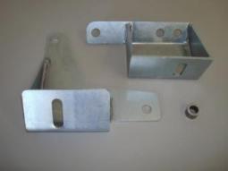
Both the top and bottom radiator mount 'cups' use C-brackets, bottom has the open ends upward and the top ones facing inward. By attaching rigid braces vertically between the top and bottom 'cups' it provides a solid mount for the fan but one cannot install/remove the radiator easily as the top cups must pivot during installation and removal.
As this is a multi-dimensional problem, let's just focus on the fan for the example as it would be easier to visualize.
When the radiator is slipped inside the top 'cups' you need to have it 100% vertical as the lower hose bung is wiggled around the cup, then carefully slid downward. Once it's about halfway in, it is angled toward the front to meet the lower 'cups' where it is pushed into place. At this point, the top and bottom 'cups' are located on the same plane, approximately 1/4" above the core, and the upper hose barb is above the upper 'cup' on the passenger side.
By welding a bolt to the rear face of each 'cup', you create the means to make the whole cradle rigid and provide a solid place to mount the fan.
Since the radiator is 26x19x3, let's say just for the sake of example that it is 17" center-to-center between the top and bottom 'cups'. I haven't measured this, so the 17" figure is conjecture for the time being. When you link top and bottom together, the top can no longer rotate as it needs to do in order to remove the radiator. For the fan mount, I'm going to remedy this by slotting the bottom holes upward about 1/2" to let the captured bolts slide through without binding up. Top holes will require minor slotting to allow for the angular difference.
Since the Taurus fan is a bit less than 26" wide (again, I haven't measured it), its shroud will be reconstructed and bolted on the radiator-side of the vertical links to get it as close to the radiator as possible. As long as the fan frame keeps the center of the fan blades about 1/8" off of the core, it should work fine and hopefully the rear will clear the main pulleys.
FYI, if you cut the shroud down on a Taurus fan so it sits level based on the driver's side mounting ears, you'll have about 1/8" clearance between fan and radiator at the middle of the fan blade where it is thickest. Mine is currently modified like this.
For the A/C condenser, all you do is flip the whole idea upside-down since it'll need slotted at the top. The only change I'd make here is to use slotted steel instead of solid, in order to preserve airflow through the core in the areas where the vertical links will be.
Ran to Menards for some 1/8" thick flat steel, a square dowel rod, some Loctite-brand JB Weld
Both the top and bottom radiator mount 'cups' use C-brackets, bottom has the open ends upward and the top ones facing inward. By attaching rigid braces vertically between the top and bottom 'cups' it provides a solid mount for the fan but one cannot install/remove the radiator easily as the top cups must pivot during installation and removal.
As this is a multi-dimensional problem, let's just focus on the fan for the example as it would be easier to visualize.
When the radiator is slipped inside the top 'cups' you need to have it 100% vertical as the lower hose bung is wiggled around the cup, then carefully slid downward. Once it's about halfway in, it is angled toward the front to meet the lower 'cups' where it is pushed into place. At this point, the top and bottom 'cups' are located on the same plane, approximately 1/4" above the core, and the upper hose barb is above the upper 'cup' on the passenger side.
By welding a bolt to the rear face of each 'cup', you create the means to make the whole cradle rigid and provide a solid place to mount the fan.
Since the radiator is 26x19x3, let's say just for the sake of example that it is 17" center-to-center between the top and bottom 'cups'. I haven't measured this, so the 17" figure is conjecture for the time being. When you link top and bottom together, the top can no longer rotate as it needs to do in order to remove the radiator. For the fan mount, I'm going to remedy this by slotting the bottom holes upward about 1/2" to let the captured bolts slide through without binding up. Top holes will require minor slotting to allow for the angular difference.
Since the Taurus fan is a bit less than 26" wide (again, I haven't measured it), its shroud will be reconstructed and bolted on the radiator-side of the vertical links to get it as close to the radiator as possible. As long as the fan frame keeps the center of the fan blades about 1/8" off of the core, it should work fine and hopefully the rear will clear the main pulleys.
FYI, if you cut the shroud down on a Taurus fan so it sits level based on the driver's side mounting ears, you'll have about 1/8" clearance between fan and radiator at the middle of the fan blade where it is thickest. Mine is currently modified like this.
For the A/C condenser, all you do is flip the whole idea upside-down since it'll need slotted at the top. The only change I'd make here is to use slotted steel instead of solid, in order to preserve airflow through the core in the areas where the vertical links will be.