
4-Rotor FC Build


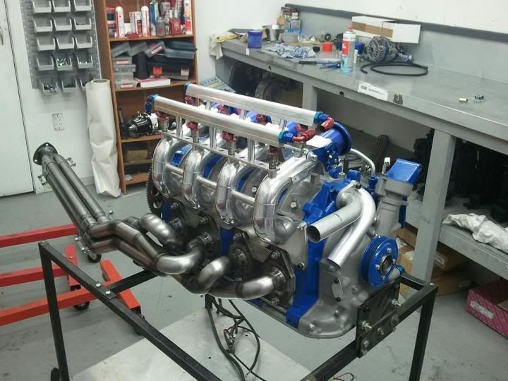
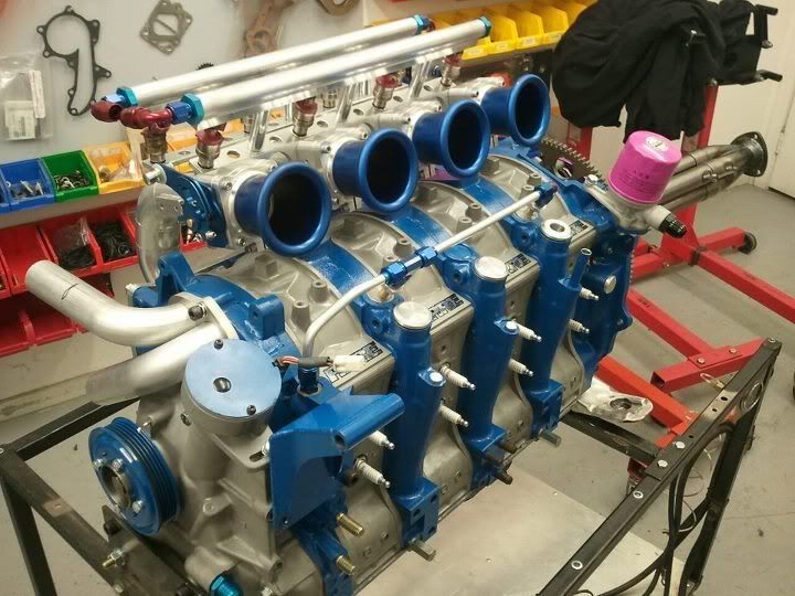
Speaking of PPRE, went into their workshop the other day while a mate was having his 7 dynoed and took a couple shots of this beauty... (Bit more progress than their FB shots...) They are certainly pumping these motors out, there was another two under construction as well!
Btw John really nice build I'll be checking this out with interest!! Bet you can't wait until its all done!
Btw John really nice build I'll be checking this out with interest!! Bet you can't wait until its all done!
Thread Starter
Joined: Oct 2010
Posts: 605
Likes: 13
From: The Netherlands
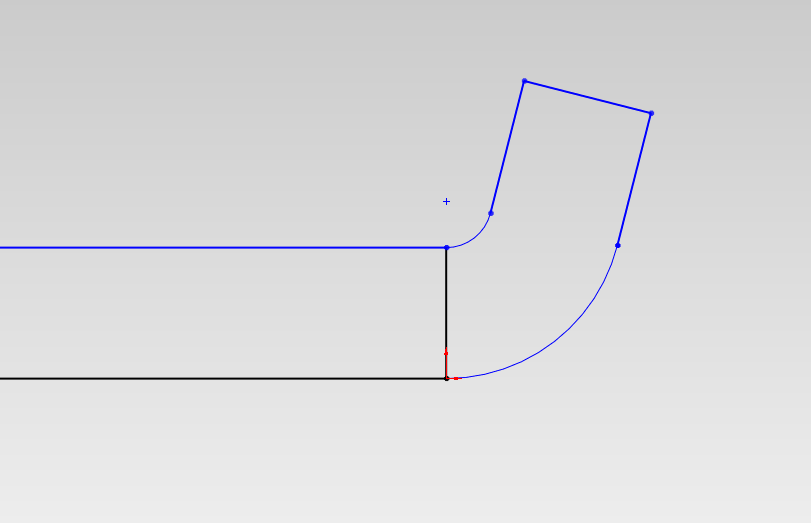
The straight edges are machined, but I used a vertical beltsander for the round edge. Doesn't need to be precision because it doesn't touch anything. Got it pretty good though.
They are nice, I want one bad.
Update
Finished the front counterweight

Finished the rear counterweight. I mounted the 4-rotor shaft in the lathe, and made sure the runout was under 0.0003". Then I mounted the counterweight and machined the oil seal surface and the flywheel mating surfaces.

Also modified my OS giken flywheel a bit, just removed some weight.

Update
Finished the front counterweight
Finished the rear counterweight. I mounted the 4-rotor shaft in the lathe, and made sure the runout was under 0.0003". Then I mounted the counterweight and machined the oil seal surface and the flywheel mating surfaces.
Also modified my OS giken flywheel a bit, just removed some weight.
Thread Starter
Joined: Oct 2010
Posts: 605
Likes: 13
From: The Netherlands
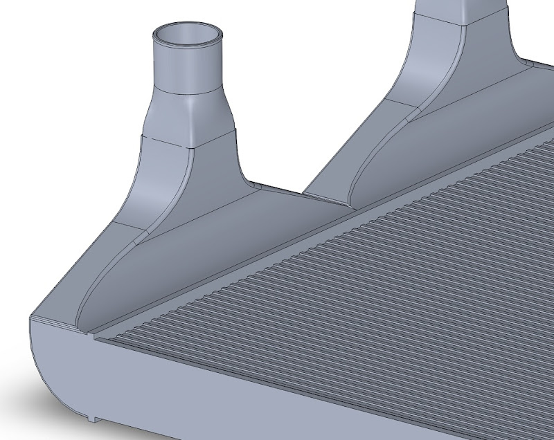
So I've been trying to design my radiator. Already got a aluminium radiator core, some 1050A sheet metal, and 2 12" cooling fans. Now I need to figure out how I'm going to design and fabricate the end tanks.
Here is the first design I made. I'm going with the endtanks on the side, because else the coolant hoses will interfere with the hood vent.

Also did some simple flow analysis

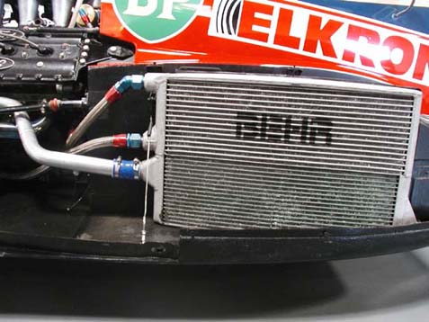
The colours represent coolant velocity, this is assuming the waterpump can pump about 125 l/min. I don't know if it pumps that much, but won't matter because this analysis is just to compare different designs. It's clearly visible that the water has to flow through a pretty sharp bend, which doesn't do good things for flow. This causes a few parts of the radiator core to be pretty ineffective. Also the pressure differential over the radiator was 4.5 psi. So I looked at some serious racing radiators, and almost all of them have something like this (look at the lower part, the upper part is the oilcooler)
Instead of a sharp bend they put in a piece that smooths out the flow.
So I designed a new radiator:
And checked the coolant flow

Problem is still there, it's better than before but I was hoping it would be more effective. Pressure difference is reduced from 4.5 to 3 psi and flow over the radiator core looks a bit better, but I'm going to fiddle with it a bit more.
Here is the first design I made. I'm going with the endtanks on the side, because else the coolant hoses will interfere with the hood vent.
Also did some simple flow analysis
The colours represent coolant velocity, this is assuming the waterpump can pump about 125 l/min. I don't know if it pumps that much, but won't matter because this analysis is just to compare different designs. It's clearly visible that the water has to flow through a pretty sharp bend, which doesn't do good things for flow. This causes a few parts of the radiator core to be pretty ineffective. Also the pressure differential over the radiator was 4.5 psi. So I looked at some serious racing radiators, and almost all of them have something like this (look at the lower part, the upper part is the oilcooler)
Instead of a sharp bend they put in a piece that smooths out the flow.
So I designed a new radiator:
And checked the coolant flow
Problem is still there, it's better than before but I was hoping it would be more effective. Pressure difference is reduced from 4.5 to 3 psi and flow over the radiator core looks a bit better, but I'm going to fiddle with it a bit more.
What happens if you put the ports on the edge of the tank instead of the face?
Alternatively, leave the bungs where they are but angle them.
I have no grip on the math but I wonder:
Given that there's a hard defined envelope for the radiator, you seem to have opted for the largest possible core, leaving minimal room for the tanks/ports.
The end tank size and placement results in penalties in flow and pressure.
If the end tanks were increased in size to allow less disruption, the core would have to be reduced.
There must be a crossover point in overall performance, where the increase in one factor is balanced by the decrease in the other.
In other words, does improving the intake/outflow by enlarging the end tanks and decreasing the core work better than the reverse?

Joined: Mar 2001
Posts: 31,857
Likes: 3,243
From: https://www2.mazda.com/en/100th/
along those lines the BMW radiator in the pic has the radiator elbows straight out the sides, that probably won't fit, but maybe as it gets closer to straight flow gets better?
since there is more engine, it might actually matter if the radiator has some pressure drop, but really who knows?
since there is more engine, it might actually matter if the radiator has some pressure drop, but really who knows?

Did I miss the results you got back from getting the rotors themselves balanced? Was curious about that.
As many have said holy hell this is amazing! Very VERY exceptional work.
Look forward to watching it.
As many have said holy hell this is amazing! Very VERY exceptional work.
Look forward to watching it.
Thread Starter
Joined: Oct 2010
Posts: 605
Likes: 13
From: The Netherlands
What happens if you put the ports on the edge of the tank instead of the face?
Alternatively, leave the bungs where they are but angle them.
I have no grip on the math but I wonder:
Given that there's a hard defined envelope for the radiator, you seem to have opted for the largest possible core, leaving minimal room for the tanks/ports.
The end tank size and placement results in penalties in flow and pressure.
If the end tanks were increased in size to allow less disruption, the core would have to be reduced.
There must be a crossover point in overall performance, where the increase in one factor is balanced by the decrease in the other.
In other words, does improving the intake/outflow by enlarging the end tanks and decreasing the core work better than the reverse?
Alternatively, leave the bungs where they are but angle them.
I have no grip on the math but I wonder:
Given that there's a hard defined envelope for the radiator, you seem to have opted for the largest possible core, leaving minimal room for the tanks/ports.
The end tank size and placement results in penalties in flow and pressure.
If the end tanks were increased in size to allow less disruption, the core would have to be reduced.
There must be a crossover point in overall performance, where the increase in one factor is balanced by the decrease in the other.
In other words, does improving the intake/outflow by enlarging the end tanks and decreasing the core work better than the reverse?
Don't think I'll have room for angled bungs. The end tanks really aren't that small, their 45mm's wide, which is wider than with most radiators. I did want the core a bit smaller though, but the size I wanted wasn't standard, so it had to be custom made which was expensive. This one is 20mm's wider than I wanted, but it was half the money and will do. I can probably modify the chassis to give me a bit more room at the top end tank if needed.
along those lines the BMW radiator in the pic has the radiator elbows straight out the sides, that probably won't fit, but maybe as it gets closer to straight flow gets better?
since there is more engine, it might actually matter if the radiator has some pressure drop, but really who knows?
since there is more engine, it might actually matter if the radiator has some pressure drop, but really who knows?
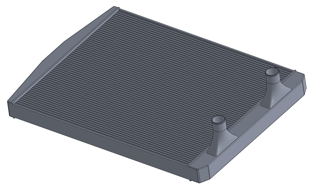
Did some more testing with different radiator end-tank designs. After a few attempts I came up with this:

The coolant entry pipe is at a slight angle, and the bottom side of the end tank has an angle in it. This should redirect the coolant flow and eliminate most of the blind spots.
This is how the coolant flow looks like:

Coolant flow velocity in different core ports

Don't think it's any better though, Dammit, I really though this would work well. I wonder if this simulation really corresponds with reality. There are a lot of aluminium radiators out there that are designed a lot more poorly than this one, and they seem to be working ok. Ah well, I still got a few things I want to try, so I'll do another attempt.
Joined: Mar 2001
Posts: 31,857
Likes: 3,243
From: https://www2.mazda.com/en/100th/
Don't think it's any better though, Dammit, I really though this would work well. I wonder if this simulation really corresponds with reality. There are a lot of aluminium radiators out there that are designed a lot more poorly than this one, and they seem to be working ok. Ah well, I still got a few things I want to try, so I'll do another attempt.
its still born, but my friend copied an endtank like one we saw in racecar engineering, its like that BMW one, but it gradually curves. kind of like this one, http://m92.photobucket.com/image/int...g.html?src=www
granted its an IC and not a radiator...


Thread Starter
Joined: Oct 2010
Posts: 605
Likes: 13
From: The Netherlands
I saw that on facebook. Very cool, but like comparing sortoff apples and oranges. That "engine bay" is the rear part of a lamborghini. So basically a chassis that can use pretty much all the power all the time, and little incoming air to cool it, so yeah they need to go big with cooling. Needed cooling isn't linked to the amount of rotors but to the hp your making, so fc's with a decent turbo conversion are probably better comparing material.
Good idea, but hurts flow though. I might do something like that if I can't find a decent design.
Did some more testing today. At first I followed tegheim's roundshaped idea, and came up with this:

Still the same problem, thank god!, that was going to be a nightmare to fabricate! The basic problem is that there is a lot of water coming into the radiator. I don't know exactly how many l/min the S4 waterpump churns out, but electric pump's are known to pump about 115l/min without resistance, and about 80 - 90l/min when installed. I think an S4 oem pump can pump more when the rpm is spinning at normal - higher rpm's, so I used 125 l/min. 125 l/min is 2.08 l/sec, with a 35mm ID coolant entry pipe flow velocity is (2.08/1000) / (PI/4*0.035^2) = 2.16 m/sec, just like the flow analysis numbers say, That's pretty quick! So basically the speed and inertia of the coolant makes it not want to change direction which explains the blue swirling and all my attempts failing. So I had to think at a different angle, which I litterally did

And the flow patterns:

Still some swirling, I think it's because the end tank has gotten too big. The coolant is divided better over the entire core though, and pressure drop is down to 0.18bar. It's also reasonably doable to fabricate. I might mess around with making the endtank smaller but we might have a winner
Did some more testing today. At first I followed tegheim's roundshaped idea, and came up with this:
Still the same problem, thank god!, that was going to be a nightmare to fabricate! The basic problem is that there is a lot of water coming into the radiator. I don't know exactly how many l/min the S4 waterpump churns out, but electric pump's are known to pump about 115l/min without resistance, and about 80 - 90l/min when installed. I think an S4 oem pump can pump more when the rpm is spinning at normal - higher rpm's, so I used 125 l/min. 125 l/min is 2.08 l/sec, with a 35mm ID coolant entry pipe flow velocity is (2.08/1000) / (PI/4*0.035^2) = 2.16 m/sec, just like the flow analysis numbers say, That's pretty quick! So basically the speed and inertia of the coolant makes it not want to change direction which explains the blue swirling and all my attempts failing. So I had to think at a different angle, which I litterally did
And the flow patterns:
Still some swirling, I think it's because the end tank has gotten too big. The coolant is divided better over the entire core though, and pressure drop is down to 0.18bar. It's also reasonably doable to fabricate. I might mess around with making the endtank smaller but we might have a winner

Who would have thought that building the radiator was such a trial and error process? This is why im going to RIT in the fall for Mechanical Engineering Technology cause I love this technical stuff!!
Senior Member
Joined: Nov 2003
Posts: 533
Likes: 3
From: Sweden
You dont need to do inner radius on my example. Just do an ordinary, and round up the back of it.
Well, though you have a little intake, and it will get bigger very fast, the swirl will be there.
I would go for a thicker, but less complicated design. The flow-problem will always be there, but maybe its enough to cool 1000hp anyway?
Hot-spots in the radiator aren't that bad. Worse if its in the engine