When you click on links to various merchants on this site and make a purchase, this can result in this site earning a commission. Affiliate programs and affiliations include, but are not limited to, the eBay Partner Network.
I know this has been covered before but some people have planted the seed of doubt in my mind.
It seems obvious to me that this would work as this it one of the main usages of relays. But some say that the contacts on the relay would fowl just as easy.
I guess I'm going to do this anyway as, even if the relays get fowled at least they are cheaper and more readily available than window switches.
Well, one advantage of a relay vs. switch is that it is not 20 years old.
Use *QUALITY* relays. I used Bosch/Tyco *brand* 20/30 relays. I bought them on ebay. I think I got 10 relays and sockets for around $30 shipped. Use the interlocking sockets so you can easily replace the relay without touching the wiring. Search ebay for "bosch tyco relay" and you will find the vendor. He sells 5 packs and 10 packs.
I have done this mod on my 90 vert. I interlocked the sockets and tek-screwed the relay mounting tabs into the inner door panel, turned so the body of the relay is internal to the door cavity. No rattling, the wiring is easily routed and there is easy access if I need to get to them.
I cannot tell you how much better the windows work. They both move fast and smooth indicating that window motors are now getting full voltage. The relay contacts obviously have a higher amp capacity than the OEM switches.
In every other car I have you can hear relays 'click' in the door when you operate the windows. Now, my Vert 'clicks' the same way. Using a relay is the modern and accepted way to activate power windows.
The factory S4 power window switch is rated to 15 amp, while the factory S5 power window switch is only rated to 10 amps.
This means, using a P&B (Potter Brumfeild) or DEI 40/30 Relay you are doubling or tripling the current capability of the switch.
This means the likelihood of contact failure is almost complete eliminated. I would not consider ever putting a new power window switch in, that I didn't wire up to relays.
Also, I wouldn't wire the passengers switch up like that. I would use the existing wiring for the power that runs to the drivers side, and not use independent power so that you can retain the lock out feature of the drivers switch.
I dont think Im totally seeing this, but form what I gather you are saying to put the relay for the passenger side, on the drivers side.
But wouldnt the passenger side switch not make use of the relays then?
If you have a minute to sketch something out real quick it would be really helpful
that "schematic" fails.
A. because they probably used MS paint.
B. because when i wired it this way, the passangers window could not be controlled by the drivers side switch.
Of course someone correct me if im completely wrong here.....
Im not even sure that would work correctly wiring it that way
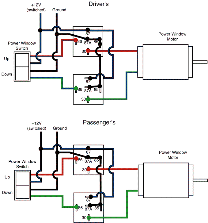
First off you really only need 4 prong relays
The other things I see wrong are the 30 terminals need to be your constant power so your blue wire in the diagram.
Your motor would need to be hooked to 87
What will happen when you press the switch sending power to 86 is your relay will make the circuit connection between 30 and 87 sending power to the motor.
If you used the 5 prong relay and hooked power to 30 and ground to 85 and 87A it would short out because 87A is normally open and sending voltage out
he says to ground to the door metal but I measured the ground of my door and it�s not a very low resistance pathway it seems. I grounded to the side mirror motor ground wire
Just want to mention that this write up or mod is not well documented. And not to mention its bulletin. It doesn't work. Esp the way all the purists here want it to. You have to add ground and power to it for them to work like modern day windows. Not to mention all thr bs explanations dont help at all. Everyone here was completely wrong esp the guy with the matrix avatar. Like bro you gave wrong information and thought you were neo. No. Youre better off cutting all words and make dedicated power and ground. This whole chat just pissed me off and wasted my time. Ty
i still have parts to make plug in window switch relay kits, to take the load off the switch and convert it to pass through dual 451m relays for driver switch and single for passenger side. not exactly cheap but still cheaper than new window switches every few years.
100% plug and play with factory style TECO connectors
Originally Posted by SikFC3S
Just want to mention that this write up or mod is not well documented. And not to mention its bulletin. It doesn't work. Esp the way all the purists here want it to. You have to add ground and power to it for them to work like modern day windows. Not to mention all thr bs explanations dont help at all. Everyone here was completely wrong esp the guy with the matrix avatar. Like bro you gave wrong information and thought you were neo. No. Youre better off cutting all words and make dedicated power and ground. This whole chat just pissed me off and wasted my time. Ty
difficult to be totally purist on a 40 year old car that had sub standard electrical issues even when it was brand new... there's nothing wrong with anything that was written above. and Icemark is gone now(he was my friend and he passed away 15 years ago), he can't respond to your petty remarks.
Last edited by notanymore; Jun 30, 2025 at 08:08 AM.
i still have parts to make plug in window switch relay kits, to take the load off the switch and convert it to pass through dual 451m relays for driver switch and single for passenger side. not exactly cheap but still cheaper than new window switches every few years.
100% plug and play with factory style TECO connectors
I did a similar plug & play window switch mod with the DEI 451m's years ago and just recently did the same on my FD. FYI, if you already have one 451m installed in the passenger door for the passenger window motor, then you don't need that 2nd DEI 451m for the passenger window installed on the driver's side door. If I get time later, I'll post up the FC wiring schematic to explain why in detail, but IIRC the gist of it is the passenger window switches in both doors are wired in parallel, so having the a 451m physically in the passenger door passing full current to the motor effectively shunts that current around both passenger window switches, protecting them both.
that's true, i built the kits a while back and mostly the passenger door kit i offered for those who for whatever reason opted out of the driver side one(and costs half as much to build and sell).
i also would like to do the same for the sunroof at some point.
Last edited by notanymore; Jun 30, 2025 at 11:26 AM.