When you click on links to various merchants on this site and make a purchase, this can result in this site earning a commission. Affiliate programs and affiliations include, but are not limited to, the eBay Partner Network.
The electrician in me is saying eww right now. Tho this is most likely not your problem, since you have found a plug wire that was way outside matching resistance to your others, I do have a suggestion. When you make up grounds or any connection really, you need to make sure you do not have any insulation touching / under / obstructing the fastener or terminal. When you make up those grounds you should have of course clean connections, but be able to see the ring all way around the fastener. When insulation gets underneath, it creates a poor connection. Also, dielectric is an insulator. It�s one thing to put it on top of your connections, but It just bugs me when people put it between then assemble them. It�s kind of counterproductive. I would change that flange bolt out for something a little smaller. I find Allen head stuff works well for ring grounds. Or you could just cut some insulation back. Just my two cents.
Just keep plugging away at your issue, most would�ve given up by now. Way to hang in there.
~ GW
thanx for catching that, i will do that when it goes back together, right now i still have the grounds off.
i usually do the same, not sure how i missed that but thanx for pointing it out
yea its def starting to get old lol never ending
drive a few weeks, go to dyno. find out i have an issue, drive for a few days, then park for months to diag and replace parts
its like the 4th time already hahahahaaha
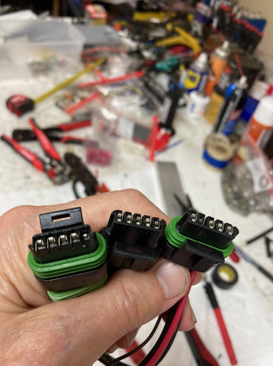
ya @TeamRX8 im trying to keep downtime to a minimum this time and getting things moving. i cant really test anything right now since alternator is out to DC for inspection, so i fgured id change this coil connectors (since i dont see anything really wrong with them anyway and doubt it is the problem.) im mainly replacing to keep tuner happy and eliminate it as a possibilty
i will be testing with spark tester with old and new spark plug wire though once that comes in and alternator arrives
Just a note, when you do Haltech firmware updates you need to make sure your coils are unplugged. The default on haltech is not IGN1a friendly and can inadvertently send 100% duty cycle to the coil which will damage them. If it were my car I would absolutely replace all four coils at this point which as much headache as you've had. I would also ensure you have at least a 4AWG welding cable running from the ground on top of the engine directly to the negative batter cable, absolutely do not rely on the chassis alone to be any sort of reliable ground path to the battery. FD's are effectively seam sealed together which is not conductive. I had similar issues with my IGN1a's and ended up completely replacing them after re-doing grounds which resolved the problem for me. Good luck, it is a painful problem.
might look into replacing coils,
I have 0 gauge wire from trans directly to battery ground so hopefully that's enough
I would argue that is not enough. Star grounding pattern is required with IGN1a as they are extremely sensitive to ground paths. I would extend that ground cable to the same lug you use under the intake manifold for the sensor ground out of your haltech harness. That should be your star point going out to all grounds. Given the symptoms the IGN1as may already have seen 100% duty cycle. Couple indicators of failure: Bulging coil packs, coil packs running at different temps when checked with an IR Thermometer. Scorch marks on any of the wiring coming from the ignition driver in the haltech to the individual coil connectors. Not an exhaustive list nor are they required to indicate an issue.
in your defense, it�s hard to think straight in a cage full of squawking parakeets
btw, did you use the coil tester yet?
.
have not yet, i sent my alternator out. waiting for them to check and resend back. was hoping would hae been a quicker process but nope
and yes i agree, trying to pick and choose what kind of makes on my side. i would love to see what that out of spec spark plug wire will look like firing. and also do you test just at idle @TeamRX8 ?
as far as grounds go i will def post pics of the engine grounds when im done cleaning them. i have 3 seperate grounds for them. engine (each rotor housing), chassis and battery. maybe ill double check my chassis ground for coils?
I did ohm test all 4 coils and they seem to be to within in the spec according to aem specs I found on this forum they all seem ok
and I believe I will change one of the grounds on coils. From what I been reading I should change my "chassis" ground which is Pin B (logic sensor ground) from chassis to a sensor ground
sorry about slow updates, this alternator is holding me back
but here are the two "discharge grounds"
sanded under wire terminal and used an allen head as suggest before. cleaned off any heartshrink that might get caught under bolt head. made sure both were tight
dielectric grease will be added only on top of connectections
I also picked up an oscilloscope that I'm trying to figure out how to use
this video is an amp ramp ofrather coils at idle, maxing out at about 11 amps. free recfing was about same
I've used oscilloscopes, and I've used a clamping current probe to measure a car's ignition coil charging time just like you've got displayed in your second video. I've never seen a dual-ramp shape like that, it's usually more of a simple triangle shape.
Was your probe watching the current from a pair of coils? Because my guess is we are seeing the leading current (then both leading and trailing) and then the first dropoff is when the leading coil fires but the trailing coil is still charging up. If you're seeing that current when just watching the power for a single coil, there might be something odd happening with the coil trigger or the coil reference ground (the one that goes to the ECU sensor ground). Try watching coil charging current for another car to compare against, if you haven't done that already.
yes the the waveforms i have seen on normal cars have been like you explained, single trianglish shapes
this one looks like it's building up (dwell), releases but then builds up again.
I posted picture on a facebook scope group to see if i get any suggestions
one person did say it looks like a multi strike type waveform
I have not tested another fd yet no
also I'm supposed to be direct fire, im trying to get a better reading on the spark plug wire to get a kv resding on wire
the one fuse I clamped on from, I'm assuming powers all 4 coils
If you're clamping on a shared power wire, you are probably just seeing two coil charging events overlapping. That's not something you would see on a non-rotary car since they rarely have two coils charging at the same time. You could try disconnecting both of your trailing coils to confirm the waveform goes back to a normal triangle-looking shape, or move the current probe so it only measures the power wire feeding one coil (after the power wires branch out to 4 individual wires).
The challenge of an oscilloscope is the coil signals happen much more than once per second, so it will be hard to see every signal firing event at high RPM when just watching with your eyes. If your device can store the waveform to memory and let you play it back for review later, it would be wise to learn how to use that function. If you can catch whatever is happening at high load or high RPM, the scope measurements might help find a reason for the the rough-looking dyno trace.
ya good idea, ill try just one feed wire and see if it changes, and yes it does have a record or buffer
im trying to get a wave reading on the secondary ignition on wire but was super noisy. not sure why
Originally Posted by TeamRX8
what dwell are you running?
.
it's on a 3d table . idle i think ir was 3.5ms but goes up as high as 4.5 under loas i believe
I agree 3ms dwell should be plenty for idle. I know a talented tuner who has done lots of big-power (piston-engine) cars, his opinion is to use the lowest coil dwell that will run smooth and avoid misfires. The theory he explained is high dwell self-heats the coils, and that's not helpful.
Another challenge of using an oscilloscope on a running engine, there is a lot of electromagnetic noise that happens each time there is a spark event. You'll usually see it if you watch a steady voltage (like the 12V battery), there will be brief spikes (less than 1.0ms) each time a spark plug fires. This is normal, you can't really prevent it, but that electromagnetic noise gets picked up on the oscilloscope probes (the wires act like a little antenna) and can make your readings seem weird. I once spent an embarrassing amount of time trying to find a crankshaft signal problem which was actually a normal crankshaft signal plus the spark noise that got picked up by the oscilloscope. I eventually realized that it was a bad measurement on my part, not a problem with the crankshaft signal.
driven it last 2 days, not feeling a huge difference. so not sure if fixed or not honestly
don't really know where to go from here, I sent a 3rd gear pull log to tuner to see what he thinks.
just running pump gas map at 14 psi, not feeling break up. feels good, tuner also believe I should feel a big difference which im not.
minor updates but I think a good one for a change!
drove it and turn the meth on, was able to hit 18 psi of boost and didn't feel break up like I did on dyno.
it does seem to havw more power i think then the 15 psi map. before it felt noticeably slower when I used the meth map
some areas of map was alil fat, close to 10 afr but we never touched that part of map on dyno since we never revved it that high.
i sent logs to tuner to see what he thinks on his end but i think we are on right track for once!
boost response does seem alil leggy on bottom, I'll thru some pics of logs tonight. egts are around 1600-1700f on top end
emap at 6500 rpms was approaching 1:1 with imap, at one point barely was higher but then started getting less then imap again
What's the story on the alternator? Did the repair shop/vendor have anything to say about it? Assuming it was put back on the car. My money is on a faulty alternator, whether it was over or under discharging voltage. Everything you've done has been for the better and will certainly improve any symptoms.
 04-19-23, 07:51 AM