
Tegheim - Home made 4 Rotor Wolvo project


Full Member
Joined: May 2002
Posts: 200
Likes: 0
From: Wichita, Kansas
this is one of my favorite videos of the 787
http://www.youtube.com/watch?v=vqQEAfPnhio
Thread Starter
Senior Member
Joined: Nov 2003
Posts: 533
Likes: 3
From: Sweden
Have made my own tool for the little jack into the loosen shaft-parts. Don't know the english word for it.
3.40mm wide and 5.70mm deep. Then put an insert for a lathe there, tada!


Have made my own tool for the little jack into the loosen shaft-parts. Don't know the english word for it.
3.40mm wide and 5.70mm deep. Then put an insert for a lathe there, tada!
3.40mm wide and 5.70mm deep. Then put an insert for a lathe there, tada!
Have made my own tool for the little jack into the loosen shaft-parts. Don't know the english word for it.
3.40mm wide and 5.70mm deep. Then put an insert for a lathe there, tada!
I always wondered why Mazda never used that engine again...
Then again if they kept making it, this cool thread probably wouldn't exist so meh
Thread Starter
Senior Member
Joined: Nov 2003
Posts: 533
Likes: 3
From: Sweden
This picture maybe help you all understand what I'm about to try out.
This is an 20B-front just for show.
I will now make an fixture to hold the same of mine, the with the spindle off, cut about 0.1mm at time i stages untill i got the right keyway.

This is an 20B-front just for show.
I will now make an fixture to hold the same of mine, the with the spindle off, cut about 0.1mm at time i stages untill i got the right keyway.

Thread Starter
Senior Member
Joined: Nov 2003
Posts: 533
Likes: 3
From: Sweden


Thread Starter
Senior Member
Joined: Nov 2003
Posts: 533
Likes: 3
From: Sweden
Time for a little update!
Sadly my HTC Desire isn't the best camera in workshop-lights...
Have finally got along with the Keyway!
First, I did new irons to the vise (correct name? Google translate)
They are mounted from the inside with M10-bolts

A hole at 43.61mm, and an Radius 6.0mm to give clearance for Radius 5.0mm on the eccentric.
This is not bored, so the surface is just roughed yet.
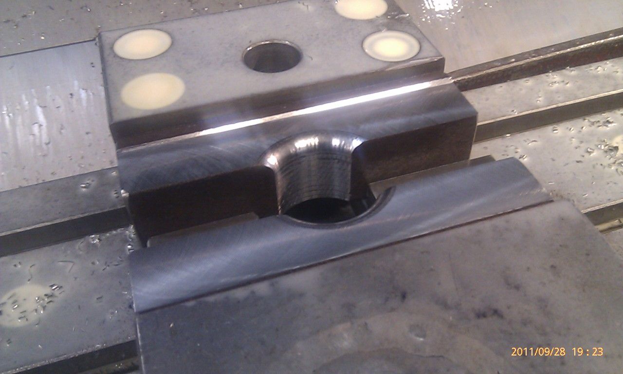
Exact precision!

Like a glove!

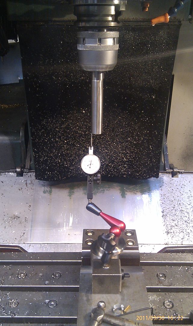
Indication of a cam, I have my zero point where I did the fixture, so then you have easy track of the eccentric theory should lie on the X 15.0mm Y0.0mm.

A final inspection of the tool. Indicates the track of the tool in the X-axis, thus I know that it is angled precisely 90grd.
Using the M-code M19 in the machine, so I lock the spindle in the same place every time.
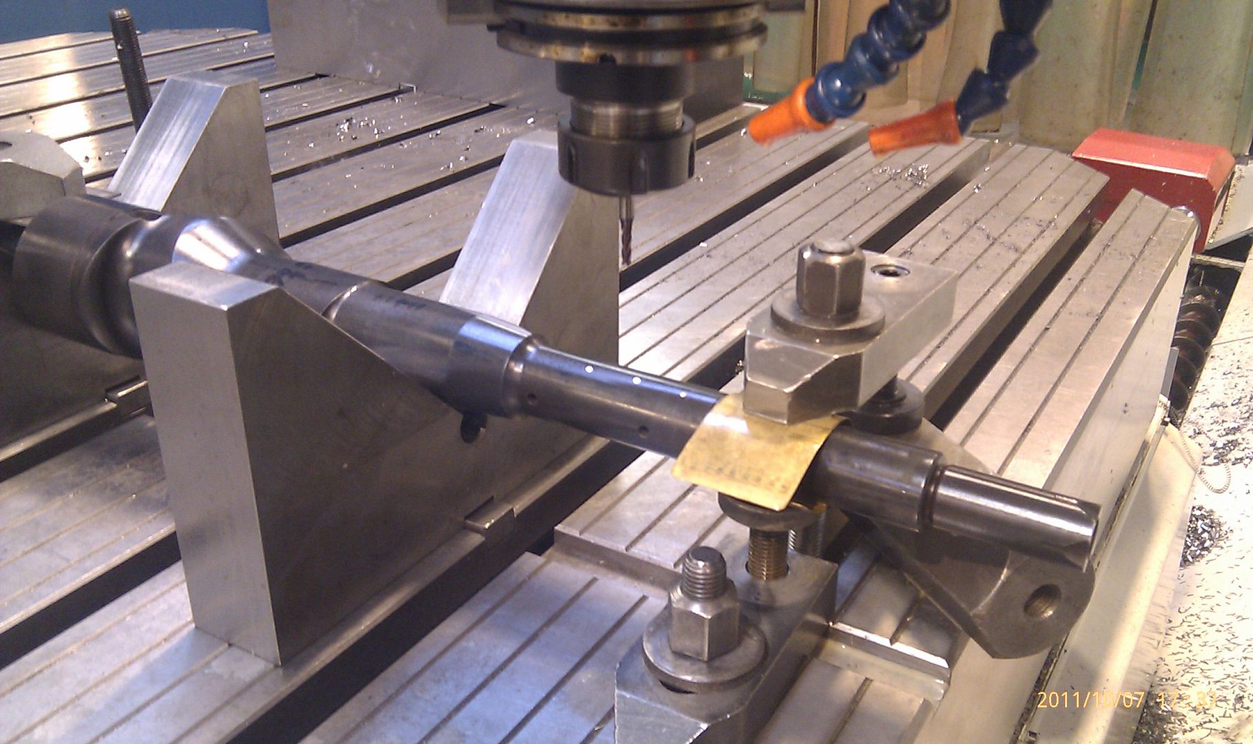
This is what working out, it will actually go much faster, when the cutting speed in such a cut is about 80-120m/min, ie as soon as it will go through the material. Easy as it spins to get the cutting speed, but now the cut stands still. So I drive 2m/min or F2000.0 as many may know. Takes just 0.1mm per insert to avoid accidents in my fine pieces
http://www.youtube.com/watch?v=wqGoEAxAFRQ
Results! Keyway on 5.00-5.01mm width, and depth with little clearance.


Sadly my HTC Desire isn't the best camera in workshop-lights...
Have finally got along with the Keyway!
First, I did new irons to the vise (correct name? Google translate)
They are mounted from the inside with M10-bolts
A hole at 43.61mm, and an Radius 6.0mm to give clearance for Radius 5.0mm on the eccentric.
This is not bored, so the surface is just roughed yet.
Exact precision!
Like a glove!
Indication of a cam, I have my zero point where I did the fixture, so then you have easy track of the eccentric theory should lie on the X 15.0mm Y0.0mm.
A final inspection of the tool. Indicates the track of the tool in the X-axis, thus I know that it is angled precisely 90grd.
Using the M-code M19 in the machine, so I lock the spindle in the same place every time.
This is what working out, it will actually go much faster, when the cutting speed in such a cut is about 80-120m/min, ie as soon as it will go through the material. Easy as it spins to get the cutting speed, but now the cut stands still. So I drive 2m/min
or F2000.0 as many may know. Takes just 0.1mm per insert to avoid accidents in my fine pieces http://www.youtube.com/watch?v=wqGoEAxAFRQ
Results! Keyway on 5.00-5.01mm width, and depth with little clearance.


It sure is fun though I work with AutoDesk Inventor for my job and have always considered modeling up the parts of the motor & engine bay to aid in making my own custom parts down the line. I just don't have that much free time and all the measuring would be extremely labor intensive. What have you been using for your measurements of the various rotary parts? Do you have drawings that you've been working from? or have you been using a CMM or laser scanner? or what?
I work with AutoDesk Inventor for my job and have always considered modeling up the parts of the motor & engine bay to aid in making my own custom parts down the line. I just don't have that much free time and all the measuring would be extremely labor intensive. What have you been using for your measurements of the various rotary parts? Do you have drawings that you've been working from? or have you been using a CMM or laser scanner? or what?
Thread Starter
Senior Member
Joined: Nov 2003
Posts: 533
Likes: 3
From: Sweden
That takes time, but it's fun!
I have never seen any drawings for the rotary-engine, but it would be fun to get one
Tonight I made a little keyway in the crank, which corresponds to the ones I did in the eccentric.
A male cutter, one must have ...

Important to buckle without moving it!

Finished setup.
work work

That did it! The track is 5.01 mm wide and 43.5 mm long.
Easy to forget compensation for the shaft shall be grinded then when you set the depth.


Junior Member
Joined: Jan 2011
Posts: 21
Likes: 0
From: Bellingham, WA
The term you want is jaws.
Also, just because it's a really cool process, the way you cut the keyway is a variant on what, in English, is called broaching. That is a really clever way to use your mill to cut a keyway.
Amazing work so far, can't wait to see the finished product.
Also, just because it's a really cool process, the way you cut the keyway is a variant on what, in English, is called broaching. That is a really clever way to use your mill to cut a keyway.
Amazing work so far, can't wait to see the finished product.


