4-Rotor FC Build
 03-19-12, 12:44 AM
#476

I was thinking on the starter and remembered 2.2, and 2.5 diesel B series trucks (~1984). They used the f block which has the same transmission bolt patern as the rotory and a similar looking transmission. Looked up the starter and it has a similar nose to the rotory starter. Don't know for sure if it will fit but something to look at. Diesels need way more starting torque.
 03-19-12, 01:54 PM
#477
Senior Member

....., I can do some flow simulations but nothing as advanced as GDI or something like that without spending lots of time and effort. I did think about placing the injectors in the rotor housing, not in the combustion area, but in the top area of the housings. There is some info on that on page 2 or 3 or something of this topic.
http://www.youtube.com/watch?v=miN3c...eature=related
The narrator states "it has a cooling effect". My guess the cooling is in large part due from the extreme drop in fuel pressure.
03-19-12, 02:04 PM
#478
Full Member
Join Date: Jan 2009
Location: 760 Ca
Posts: 137
Likes: 0
Received 0 Likes
on
0 Posts
Looking closely at this video of the Mazda's turbo 2.3 GDI , the fuel spray occurs during the intake cycle :
http://www.youtube.com/watch?v=miN3c...eature=related
The narrator states "it has a cooling effect". My guess the cooling is in large part due from the extreme drop in fuel pressure.
http://www.youtube.com/watch?v=miN3c...eature=related
The narrator states "it has a cooling effect". My guess the cooling is in large part due from the extreme drop in fuel pressure.
according to my monitoring device, at stockish boost (16.5) Ill see upwards of 1700 psi at WOT.
pressure drop with fuel on these engines is a no no.
03-19-12, 02:36 PM
#480
As far as modeling the exhaust manifold, I like to use sweeps and different profiles, but find that difficult to recreate in real life haha. What I mean is did you create each piece of tube and create an assembly? Or are you just really that good at creating sweep patterns in Solidworks?
Good work with the build as always its always a pleasure and motivation when I see your progress.
Good work with the build as always
its always a pleasure and motivation when I see your progress.
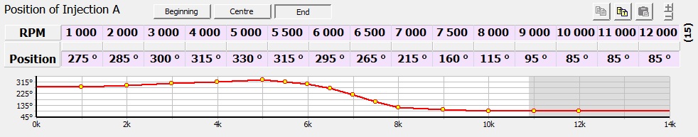
The ecu I've got is fully sequential, and I can time the injection using a table like this (this is a printscreen from the programming software), so I might be tempted to try it once the engine is up and running since I've already got the all the needed components. First things first though.
 03-19-12, 05:19 PM
#481
Senior Member
So John, sounds like you'll be fabricating 12:1 titanium rotors soon after you get DI incorporated. Good point about eliminating flames w/DI. That one went over my head.
Last edited by Clubuser; 03-19-12 at 05:48 PM.
03-19-12, 05:33 PM
#482
Moderator
iTrader: (3)
Join Date: Mar 2001
Location: https://www2.mazda.com/en/100th/
Posts: 30,900
Received 2,643 Likes
on
1,872 Posts
i think direct injection would help too, it seems to help EVERY engine... but having control over injection time should be really important too.
i've gotten such good results from a locked distributor, and carb, that i can say with sequential EFI, you should be able to get it to run like stock.
i've gotten such good results from a locked distributor, and carb, that i can say with sequential EFI, you should be able to get it to run like stock.
03-21-12, 10:59 AM
#484
Junior Member

[QUOTE=John Huijben;11022747]I also used sweeps. To make it easier to fabricate every bend has the same radius, and I just got a bunch of premade 90degr. bends of that radius. Works well, easy and cheap. Creating sweep patterns can be a bit difficult, but after about 10 header designs you get the hang of it
Awesome thank you! Ill play with it a little more when I can haha
Awesome thank you! Ill play with it a little more when I can haha
 03-24-12, 02:22 PM
#486
Update
Finished working on other people's cars so I spended the afternoon on the 4-rotor project
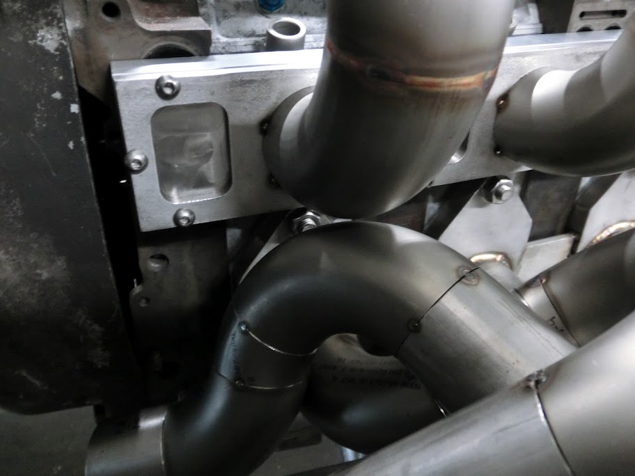
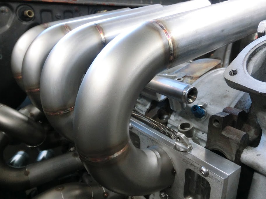
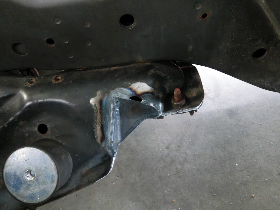
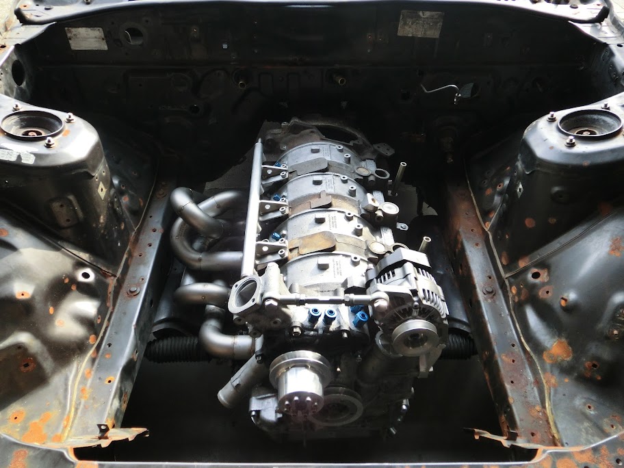
Using the 3d model I already had I made a list of all the pieces I needed for the header, got some material and cut everything to size using the bandsaw. After that I used the exhaust jig and all the pieces of pipe and bends I had and just tackwelded everything together. When that was done I testfitted the header on the car. Everything fitted well, except the #2 header pipe hitted the subframe. I already knew this was going to be close, but I just can't move the exhaust further to the engine block so I figured I'd just modify the subframe a bit if necessary which I did. So I took the engine out and did this:

Then welded in some pieces of sheet metal to close everything off
And some pictures of the tacked up exhaust header in it's future home
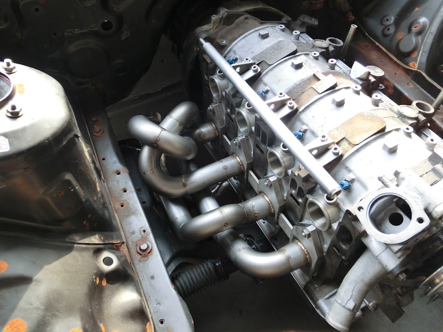

This is why the subframe had to be modified

Finished working on other people's cars so I spended the afternoon on the 4-rotor project
Using the 3d model I already had I made a list of all the pieces I needed for the header, got some material and cut everything to size using the bandsaw. After that I used the exhaust jig and all the pieces of pipe and bends I had and just tackwelded everything together. When that was done I testfitted the header on the car. Everything fitted well, except the #2 header pipe hitted the subframe. I already knew this was going to be close, but I just can't move the exhaust further to the engine block so I figured I'd just modify the subframe a bit if necessary which I did. So I took the engine out and did this:
Then welded in some pieces of sheet metal to close everything off
And some pictures of the tacked up exhaust header in it's future home
This is why the subframe had to be modified
03-24-12, 04:03 PM
#488
Full Member
Join Date: Mar 2012
Location: Toronto, ON
Posts: 68
Likes: 0
Received 0 Likes
on
0 Posts
Woah dude! The amount of fabrication and design skills you have is godlike!!! I hope one day I will have as much skill and knowledge as you do. Keep up the good work, and I can't wait to see the finished result! Heaps of vids of it running and everything 

 03-26-12, 04:50 PM
#493
Sure, no problem.
Update
Had a spare hour so started working on the muffler design. I'm going to build my own mufflers. I'm planning on using 2 mufflers in the stock location with no premufflers.
These are the 2 designs I already came up with:

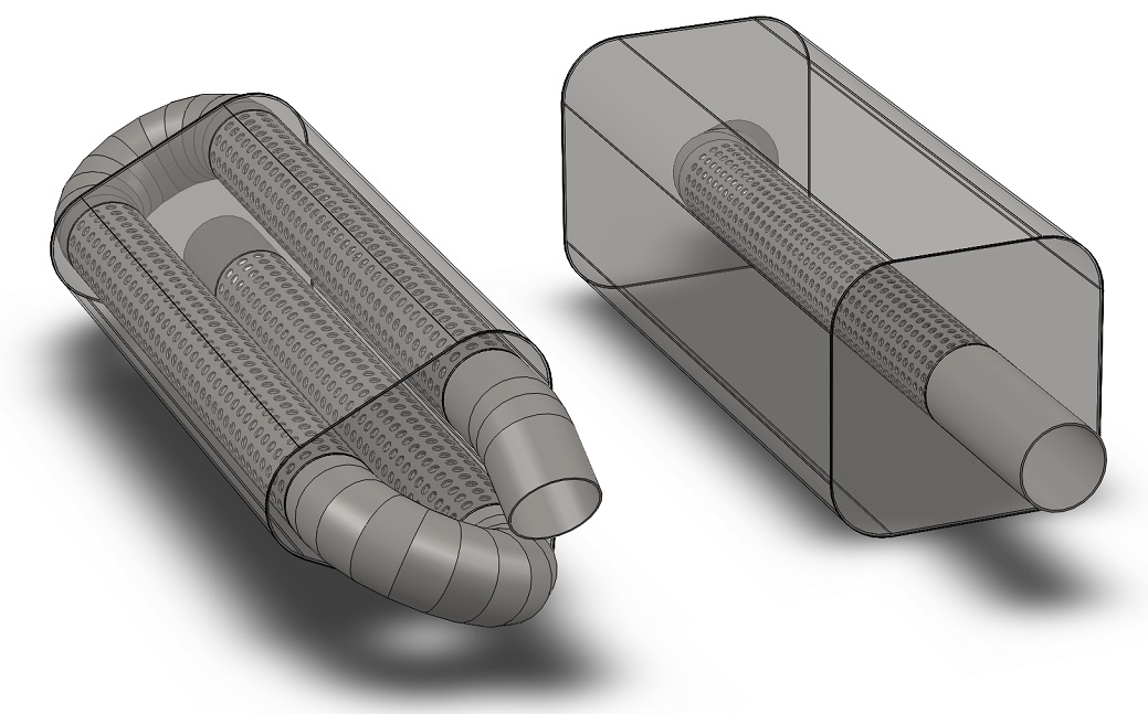
The first square design is very basic, 2,5" perforated tube, with the biggest box around it that will fit the chassis. This will be loud, but very low backpressure. The second design is a triple pass design, same outside dimensions as the other one. I think this one will be quieter, but it will create a bit more backpressure, shouldn't be a lot though. With this design there about 120 inches of perforated tube in both mufflers combined
What do you guys think?
Update
Had a spare hour so started working on the muffler design. I'm going to build my own mufflers. I'm planning on using 2 mufflers in the stock location with no premufflers.
These are the 2 designs I already came up with:
The first square design is very basic, 2,5" perforated tube, with the biggest box around it that will fit the chassis. This will be loud, but very low backpressure. The second design is a triple pass design, same outside dimensions as the other one. I think this one will be quieter, but it will create a bit more backpressure, shouldn't be a lot though. With this design there about 120 inches of perforated tube in both mufflers combined
What do you guys think?
03-26-12, 05:55 PM
#494
Moderator
iTrader: (3)
Join Date: Mar 2001
Location: https://www2.mazda.com/en/100th/
Posts: 30,900
Received 2,643 Likes
on
1,872 Posts
hmm thats a tough call. the single is obviously easier/faster to build, i'd do that if it was mine, but i'm limited by tools/skill....
on the 3 pass, i think i'd make the muffler box the same size as the single pass....
and if you wanna be fancy, build one of each, and have it run from the 3 pass at idle, and then open the other as needed....
as for the no pre-muffler thing, on a stock port i like them, but on a P port they just melt, and seem to do very little in the way of silencing either. for example, i choose poorly, and my glasspacks lasted about 3 laps, and after 30, they are sagging! Max bought a vibrant 3" presilencer, which is SS, and he melted his too, although it lasted longer, so its not just me!
03-30-12, 02:01 AM
#495
Senior Member
Every time I open this thread, I...http://www.youtube.com/watch?v=VLnWf1sQkjY&ob=av3n
Awesome work John!!
Awesome work John!!
03-30-12, 06:38 PM
#497
hmm thats a tough call. the single is obviously easier/faster to build, i'd do that if it was mine, but i'm limited by tools/skill....
on the 3 pass, i think i'd make the muffler box the same size as the single pass....
and if you wanna be fancy, build one of each, and have it run from the 3 pass at idle, and then open the other as needed....
as for the no pre-muffler thing, on a stock port i like them, but on a P port they just melt, and seem to do very little in the way of silencing either. for example, i choose poorly, and my glasspacks lasted about 3 laps, and after 30, they are sagging! Max bought a vibrant 3" presilencer, which is SS, and he melted his too, although it lasted longer, so its not just me!
on the 3 pass, i think i'd make the muffler box the same size as the single pass....
and if you wanna be fancy, build one of each, and have it run from the 3 pass at idle, and then open the other as needed....
as for the no pre-muffler thing, on a stock port i like them, but on a P port they just melt, and seem to do very little in the way of silencing either. for example, i choose poorly, and my glasspacks lasted about 3 laps, and after 30, they are sagging! Max bought a vibrant 3" presilencer, which is SS, and he melted his too, although it lasted longer, so its not just me!
Update
The intake is starting to take shape. I plan to machine out some delrin air horns that clamp onto the intake runners. That way I can easily try out shorter intake runners by removing the air filter with the air horns, cutting a piece off the intake runners, and mounting everything again. Since shortening the runners is easier than making them longer I started out with some long ones, which gives me an intake runner length of about 22,5" at the moment, I can shorten them all the way to 12,5" if needed. The long runners are making fitment tight in some spots, but it should work. Intake / exhaust clearance is very close though. I had some room on the cad model, but in real life it's too close for comfort, so I'm going to have to modify the #3 exhaust runner. Good thing it's only tacked together at the moment. Exhaust header will have some more modifications too, I ordered a 4-1 collector since I figured it would save me some work and it came in today. Even though it cost me $140 the quality was pretty bad. Nasty mig welds, bits of welding wire and junk sticking out on the inside, sharp edges everywhere. So I'm going to send it back, build a collector myself and merge it with the header.
Anyway some pictures:
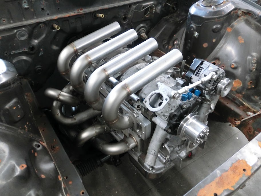
Yup, it's way too close