4-Rotor FC Build

 03-13-12, 05:16 PM
#452
i suppose the stock starter will work but for how long behind 24v is the question, will have to be in short bursts and hope it never floods. and it won't be getting recharged while driving.
Last edited by RotaryEvolution; 03-13-12 at 05:25 PM.
03-13-12, 05:20 PM
#453
The goal is to end up with a pretty normal looking FC with an insane engine. The budget and time isn't really there to go all out with the chassis, and it doesn't interest me so much. This car is also going to be driven on the street most of the time, so comfort has a small part in it too. I am running coilovers and wide rubber though.
We'll see about the starter, the TII one does seem to work fine for a 20B with all the stock auxillaries, so I'm going to give it a go like this. I've got a few of them in case one burns out.
We'll see about the starter, the TII one does seem to work fine for a 20B with all the stock auxillaries, so I'm going to give it a go like this. I've got a few of them in case one burns out.
Last edited by John Huijben; 03-13-12 at 05:23 PM.
03-13-12, 05:29 PM
#454
it probably will but i believe it will definitely be struggling. grannies mentioned it and had to resort to other methods to get theirs fired reliably, that homebrew 4 rotor on youtube sounds like a cow dying while trying to fire it up, worked though(but also believe it was a batch fire engine). probably be fine with a HD single battery with loads of CCA, like 900+.
Last edited by RotaryEvolution; 03-13-12 at 05:31 PM.
03-13-12, 05:40 PM
#455
Batch fire engines are a PITA to start, because 2 rotors build compression at the same time, while this one only has 1 rotor building compression at the same time. You see the same thing with motorbikes, 4 cil 1000cc bikes have a smaller starter than the 2 cil 1000cc ones.
 03-14-12, 02:04 PM
#458
Moderator
iTrader: (3)
Join Date: Mar 2001
Location: https://www2.mazda.com/en/100th/
Posts: 30,829
Received 2,597 Likes
on
1,845 Posts
i don't know about a 4 rotor starter, but on a 3 rotor, a T2 starter with a good battery is fine. mine initially had a PC680 battery, which worked, but had a short life. i went back to a stock battery and it was totally fine.
the other consideration is that the start map in the ecu needs to be pretty good. a stock ecu 13B car works fine with a lawnmower battery, because the stock ECU starts the car in 2-3 revolutions.
most standalones aren't tuned well enough to start in 2-3 cranks, so they need more battery....
the other consideration is that the start map in the ecu needs to be pretty good. a stock ecu 13B car works fine with a lawnmower battery, because the stock ECU starts the car in 2-3 revolutions.
most standalones aren't tuned well enough to start in 2-3 cranks, so they need more battery....
03-14-12, 02:08 PM
#459
well yes, but figuring a fresh engine with alot of variables that is when it will be most critical to have everything set up as close as possible. last thing you want to do is flood a 4 rotor with maps that are off, timing not phased properly or any of the other million things that can go wrong.
03-14-12, 08:18 PM
#460
Moderator
iTrader: (3)
Join Date: Mar 2001
Location: https://www2.mazda.com/en/100th/
Posts: 30,829
Received 2,597 Likes
on
1,845 Posts
well yes, but figuring a fresh engine with alot of variables that is when it will be most critical to have everything set up as close as possible. last thing you want to do is flood a 4 rotor with maps that are off, timing not phased properly or any of the other million things that can go wrong.
03-14-12, 08:19 PM
#461
I wish I was driving!
Stock TII starter will turn over a 4 rotor at around 250 rpms, more than enough to get a tuned map to start reliably. Keeping voltage drop to a minimum on a relocated battery (figure around 110 amps draw on the starter for voltage drop calculations for sizing your feed wire, plus load from fuel pump) is a bigger issue. The cost of a heavy gauge run of copper front to rear (more with a rear mounted kill switch) and associated weight penalties usually has individuals running too small of a wire, and reducing the available voltage to their starter. I would imagine this is the case with the grannies install.
03-15-12, 12:10 PM
#462
Senior Member

What apex seals will you be using?
What will the compression ratio be?
Do you have the capability to do intake flow simulation to determine the benefits (if any) of GDI?
Wonder what effect, by having the injector placed on the underside of the runner near the flange and fuel injected at higher pressures, have on efficiency and max power. (I realize that area is a danger zone to have injectors but still curious).
Years ago, Edlebrock had a V8 open plenum intake manifold that had a few "speed bumps" at the and of each runner. They were there supposedly to introdude turbulence hence better lower-midrange performance. But I guess on a peripheral port one might not be interested in maximizing that RPM range.
PS- Your English is Xcellent. All in the Netherlands are taught English extensively?
Last edited by Clubuser; 03-15-12 at 12:27 PM.
03-15-12, 02:49 PM
#463
Moderator
iTrader: (3)
Join Date: Mar 2001
Location: https://www2.mazda.com/en/100th/
Posts: 30,829
Received 2,597 Likes
on
1,845 Posts
not to answer for john, but yes, it was my experience that english was almost the first language in the netherlands. the swedes, germans, dasnish, belgians, and most of the french speak excellent english too.
03-16-12, 03:31 AM
#465
Like a G6
iTrader: (1)
Join Date: Dec 2007
Location: In the Dutch Mountains
Posts: 713
Likes: 0
Received 0 Likes
on
0 Posts
not to answer for john, but yes, it was my experience that english was almost the first language in the netherlands. the swedes, germans, dasnish, belgians, and most of the french speak excellent english too.
Riz.
03-16-12, 01:11 PM
#466
Senior Member
Belgium is btw a 4 languages land: Dutch, French, English, German. The 2 first are the officials.
But about the starter, 110A on 12V is pretty low a normal starter on a car (Ford Focus 1.4 zetec) draws 200A if in good condition else de Amps goes up.
But about the starter, 110A on 12V is pretty low a normal starter on a car (Ford Focus 1.4 zetec) draws 200A if in good condition else de Amps goes up.
03-16-12, 01:44 PM
#467
Moderator
iTrader: (3)
Join Date: Mar 2001
Location: https://www2.mazda.com/en/100th/
Posts: 30,829
Received 2,597 Likes
on
1,845 Posts
 03-16-12, 07:11 PM
#470
Programmable ECU, already ordered it, waiting for it to come in at the moment.
Keeping the make and type under wraps for now since nobody has ever used one on a rotary before, let alone a 4-rotor, but it should work very well.
Which is half the fun anyway  , I can think of worse things to do than toying around with a laptop and a 4-rotor.
OEM apex seals, 9.4 compression ratio, I can do some flow simulations but nothing as advanced as GDI or something like that without spending lots of time and effort. I did think about placing the injectors in the rotor housing, not in the combustion area, but in the top area of the housings. There is some info on that on page 2 or 3 or something of this topic.
smallupdate
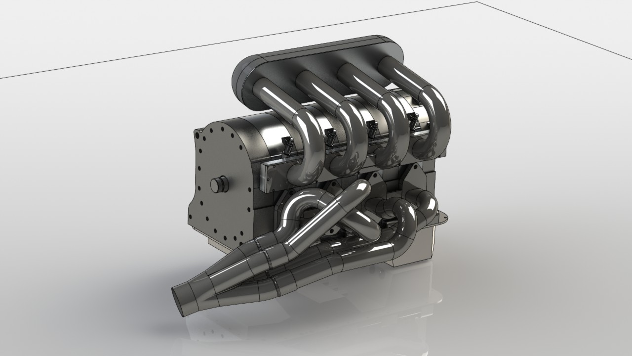
Not a lot of work on the 4-rotor has been done this week so far. I've been doing a lot of work for others, mainly on rallycross cars because the season starts next week. Did do some more exhaust designs though. Already did a basic design but it didn't fit the chassis well. I check the fitting by printing out a top, side and front view of the header on a 1:1 scale, cut it out so I'll end up with 3 templates, and check fitting with the templates on the car. That will give me a quick view of what works and what doesn't. So far I've tested 2 designs on the car using templates, just finished the 3rd one which I'll test tomorrow.
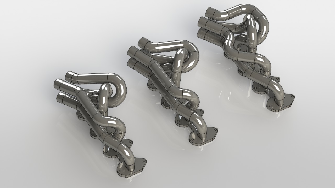
Pretty difficult to get this right, there are a lot of factors to keep track of, header length, fitment with chassis and intake runners, room for thermal expansion, ease of manufacturing, room to get to the flange nuts and collector position are just a few.
I'll get it right though
Keeping the make and type under wraps for now since nobody has ever used one on a rotary before, let alone a 4-rotor, but it should work very well.
, I can think of worse things to do than toying around with a laptop and a 4-rotor.What apex seals will you be using?
What will the compression ratio be?
Do you have the capability to do intake flow simulation to determine the benefits (if any) of GDI?
Wonder what effect, by having the injector placed on the underside of the runner near the flange and fuel injected at higher pressures, have on efficiency and max power. (I realize that area is a danger zone to have injectors but still curious).
Years ago, Edlebrock had a V8 open plenum intake manifold that had a few "speed bumps" at the and of each runner. They were there supposedly to introdude turbulence hence better lower-midrange performance. But I guess on a peripheral port one might not be interested in maximizing that RPM range.
PS- Your English is Xcellent. All in the Netherlands are taught English extensively?
OEM apex seals, 9.4 compression ratio, I can do some flow simulations but nothing as advanced as GDI or something like that without spending lots of time and effort. I did think about placing the injectors in the rotor housing, not in the combustion area, but in the top area of the housings. There is some info on that on page 2 or 3 or something of this topic.
smallupdate
Not a lot of work on the 4-rotor has been done this week so far. I've been doing a lot of work for others, mainly on rallycross cars because the season starts next week. Did do some more exhaust designs though. Already did a basic design but it didn't fit the chassis well. I check the fitting by printing out a top, side and front view of the header on a 1:1 scale, cut it out so I'll end up with 3 templates, and check fitting with the templates on the car. That will give me a quick view of what works and what doesn't. So far I've tested 2 designs on the car using templates, just finished the 3rd one which I'll test tomorrow.
Pretty difficult to get this right, there are a lot of factors to keep track of, header length, fitment with chassis and intake runners, room for thermal expansion, ease of manufacturing, room to get to the flange nuts and collector position are just a few.
I'll get it right though
03-16-12, 08:05 PM
#471
F**K THE SYSTEM!!
Most aftermarket ecu's have delayed starts dont they?(for priming purposes)
IS this why you guys think they dont start easy? When i was checking for spark i realized this. takes a few turns before the ecu even tried to send signal. But once it does it fires right up.
IS this why you guys think they dont start easy? When i was checking for spark i realized this. takes a few turns before the ecu even tried to send signal. But once it does it fires right up.


 03-19-12, 12:02 AM
#475
Junior Member

As far as modeling the exhaust manifold, I like to use sweeps and different profiles, but find that difficult to recreate in real life haha. What I mean is did you create each piece of tube and create an assembly? Or are you just really that good at creating sweep patterns in Solidworks?
Good work with the build as always its always a pleasure and motivation when I see your progress.
Good work with the build as always
its always a pleasure and motivation when I see your progress.