4-Rotor FC Build

 01-09-12, 11:31 AM
#228
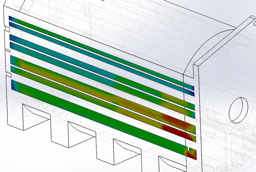
Did some computer testing with the coolant looplines which I made fittings for. If you look at the pictures you can see that the fittings are square to the flow direction. I was wondering if this would have a negative effect, I can imagine that coolant actually gets sucked out of the lines instead of pressed into them because of the flow direction. So I made a model in the computer and tested it out.
The model, front and rear plates aren't 100% accurate, but close enough for this test

And results, The middle 4 lines have looplines attached to them, The colour displays the flow velocity of the coolant, more velocity means more coolant is being pushed trough the channel. The calculation shows that coolant speed is almost doubled in these channels at the rear part of the engine, so the looplines work
Videoclip of the coolant flow
http://www.youtube.com/watch?v=QoJkS259k9s&feature=youtu.be[/img]
Results are probably not 100% accurate, but I think it shows the looplines work.
I wish, the dry sump front cover costs about the same as the rest of the engine
I'll see how far I can get with modifying original stuff.
The model, front and rear plates aren't 100% accurate, but close enough for this test
And results, The middle 4 lines have looplines attached to them, The colour displays the flow velocity of the coolant, more velocity means more coolant is being pushed trough the channel. The calculation shows that coolant speed is almost doubled in these channels at the rear part of the engine, so the looplines work
Videoclip of the coolant flow
http://www.youtube.com/watch?v=QoJkS259k9s&feature=youtu.be[/img]
Results are probably not 100% accurate, but I think it shows the looplines work.
I wish, the dry sump front cover costs about the same as the rest of the engine
I'll see how far I can get with modifying original stuff.
01-09-12, 01:02 PM
#229

reply
Yes I know about that, but it's really close to fitting so I'll probably be able to machine out the front cover a bit to make it fit without welding or anything. But i can weld a piece in there if I have to. But if you tried the same oil pump setup as me you've also encountered the problem that there is too much slack in the chain, how did you solve that? I don't want to use an electric waterpump if I don't have to because of space issues or anything. I don't think one of those will pump more than the 2nd gen one will, maybe at low rpms. If Im going to need one I will, but Im trying the 2nd gen pump first.
 01-10-12, 12:41 AM
#234
Junior Member

Absolutely incredible sir. I'm actually studying engineering and I truly find your work inspiring. I was planning on recreating my 13b in SolidWorks when I have the funds to rebuild it but this is just taking it to a whole new level haha. Your simulations, modeling, tolerances, everything looks incredible. I certainly hope I can follow your example someday as I do plan to build my car with some of my own designs. Good luck though! And if there is anything I can help with design wise let me know!
01-10-12, 11:09 AM
#235
Picked up the e-shaft today, nice and nitrated 
Also recieved some material for the oiling jets, and the oil supply tube.

MaczPayne had it right, just create a profile, open up a new 3d sketch, make a spline with various points, move the points around untill you think it's fine (the relax all handles button helps), and sweep.
Also recieved some material for the oiling jets, and the oil supply tube.
MaczPayne had it right, just create a profile, open up a new 3d sketch, make a spline with various points, move the points around untill you think it's fine (the relax all handles button helps), and sweep.
01-11-12, 05:04 PM
#239
Did some more work to the e-shaft. The part where the slip-on piece slides on needed to be machined one more time. I did this after nitrating, because I was worried the long thin shaft might bend by nitrating. The heat treaters actually sealed this part off while nitrating the rest, so I would be able to machine it afterwards. That's why this part had a funny goldlike colour in the previous picture.
All finished, took me 2,5 hours for this piece alone. Really needed to get this part right. Any flaws here and the slip-on piece will sit loosely onto the e-shaft, making it unusable

Finally I was able to assemble the shaft, been waiting a long time for this.
Looks good so far, even all the oiling holes line up perfectly
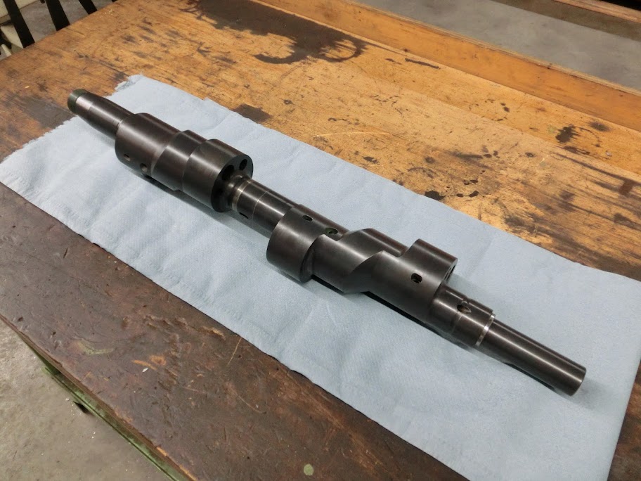
After assembly I checked the runout of the shaft. More than around 0,15mm's and I would be in trouble, but it's at 0,04mm's (1,5 thousands of an inch) so the grinding shop shouldn't have any problem getting this right. Holy crap, this thing might actually work!
All finished, took me 2,5 hours for this piece alone. Really needed to get this part right. Any flaws here and the slip-on piece will sit loosely onto the e-shaft, making it unusable
Finally I was able to assemble the shaft, been waiting a long time for this.
Looks good so far, even all the oiling holes line up perfectly
After assembly I checked the runout of the shaft. More than around 0,15mm's and I would be in trouble, but it's at 0,04mm's (1,5 thousands of an inch) so the grinding shop shouldn't have any problem getting this right. Holy crap, this thing might actually work!

 01-14-12, 12:10 PM
#245
Spended the day getting everything together under the front cover.
First problem is that the front cover itself didn't fit, so I measured it out and found that it didn't needed a lot of room for it to fit, so I just removed some material out of there. Didn't have the right boring tool to do it in the mill so I did in the lathe.
Round and round

There it is, the front cover just after machining
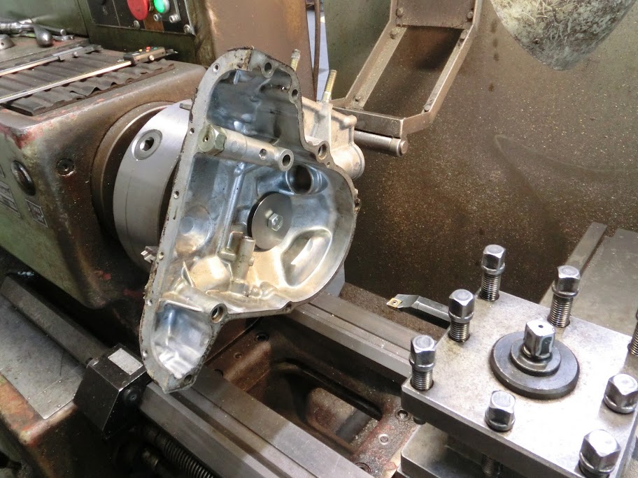
And that's all there is to it. I didn't cut through there, but I don't think the remaining material is very thick, so I'll build up the outside with some devcon epoxy for protection

It fits , Also made that MOP block off plate and that CAS block off bushing today

Problem solved, got a few mm's of room on each side
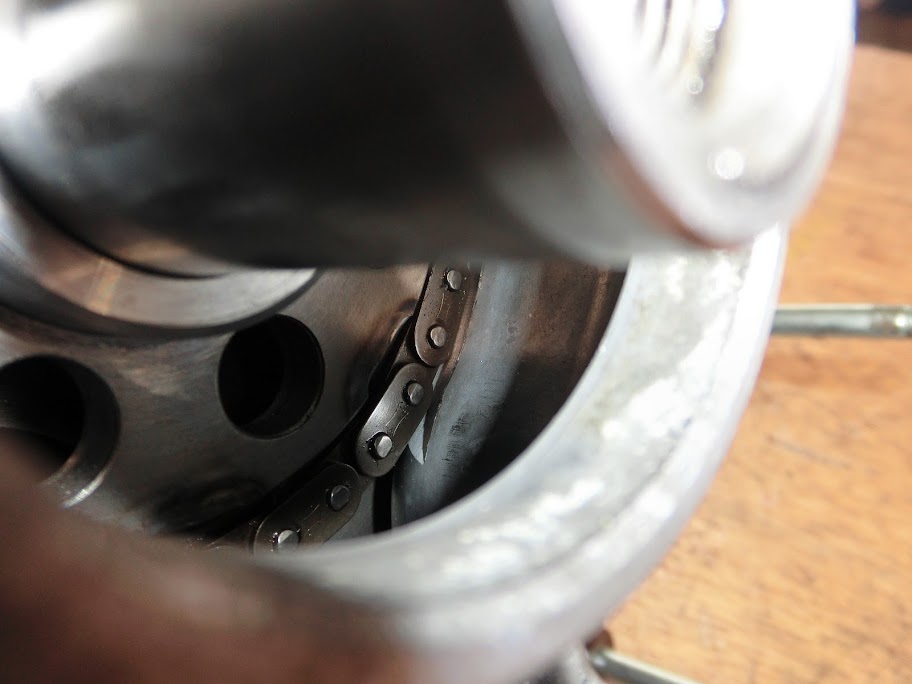
Next up was the oil pump chain. I previously made a larger drive sprocket, and fitted a chain together. Problem was that the slack got too large. The used chains weren't the problem, they came out of low mileage engines, and were well withing tolerances in the stock setup, so just getting new chains wouldn't have made a difference. The center to center distance of the sprockets just isn't suited for these sprocket and chain sizes. I didn't want to leave it like this though, slack was over an inch, so I got worried the chain might catch onto something and snap or anything. By looking at it I really couldn't find an easy solution, I figured a chain guide might work but there's nowhere to bolt one onto, and the counterweight and front oil pressure regulator easily get in the way of things. After looking at it for a while I just took a piece of 6060 alloy, chucked it into the mill and started doing something.
And here it is, an adapter to mount a chain guide to
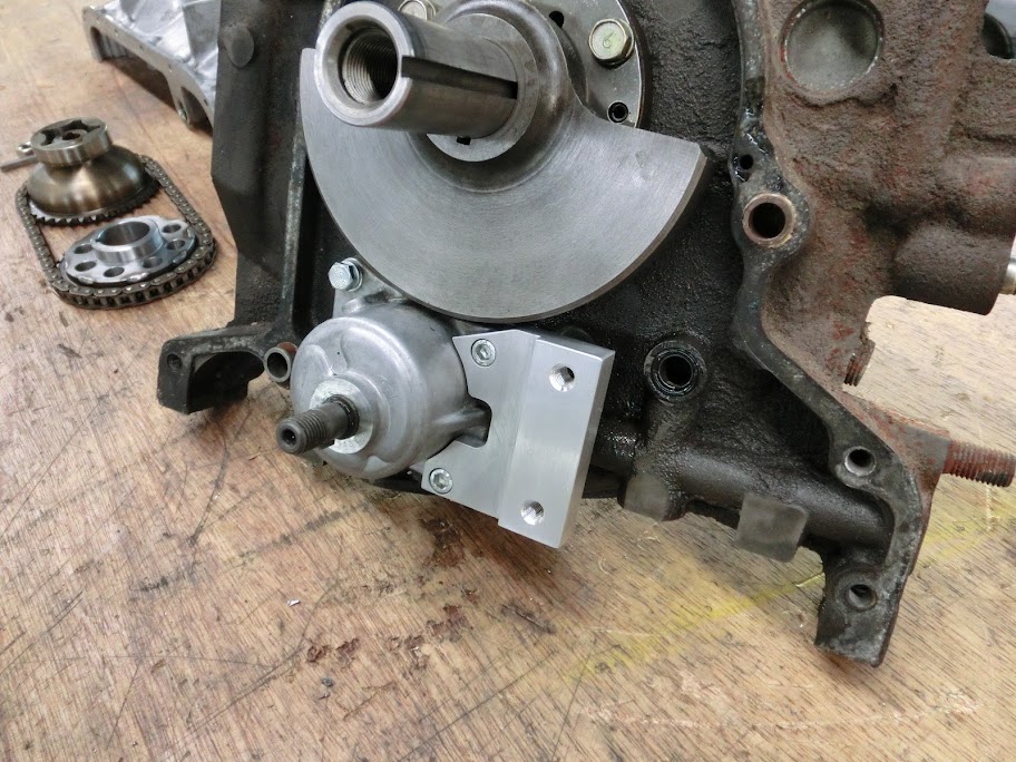
After this was done I scribbled a chain guide shape onto paper and made a part that might work. It's made from a nylon-like material that's specifically designed to guide chains.

The piece barely touches the chain, it just guides it into a curved shape. There's still about 5mm's of slack. After this pictures was taken I made a slight modification to gain some clearance near the front counterweight. Even tough this is a 4-rotor I'm still going to use that one. It's going to get machined smaller in diameter, and have a keyway added, but I don't plan to make one from scratch.
First problem is that the front cover itself didn't fit, so I measured it out and found that it didn't needed a lot of room for it to fit, so I just removed some material out of there. Didn't have the right boring tool to do it in the mill so I did in the lathe.
Round and round
There it is, the front cover just after machining
And that's all there is to it. I didn't cut through there, but I don't think the remaining material is very thick, so I'll build up the outside with some devcon epoxy for protection
It fits
, Also made that MOP block off plate and that CAS block off bushing todayProblem solved, got a few mm's of room on each side
Next up was the oil pump chain. I previously made a larger drive sprocket, and fitted a chain together. Problem was that the slack got too large. The used chains weren't the problem, they came out of low mileage engines, and were well withing tolerances in the stock setup, so just getting new chains wouldn't have made a difference. The center to center distance of the sprockets just isn't suited for these sprocket and chain sizes. I didn't want to leave it like this though, slack was over an inch, so I got worried the chain might catch onto something and snap or anything. By looking at it I really couldn't find an easy solution, I figured a chain guide might work but there's nowhere to bolt one onto, and the counterweight and front oil pressure regulator easily get in the way of things. After looking at it for a while I just took a piece of 6060 alloy, chucked it into the mill and started doing something.
And here it is, an adapter to mount a chain guide to
After this was done I scribbled a chain guide shape onto paper and made a part that might work. It's made from a nylon-like material that's specifically designed to guide chains.
The piece barely touches the chain, it just guides it into a curved shape. There's still about 5mm's of slack. After this pictures was taken I made a slight modification to gain some clearance near the front counterweight. Even tough this is a 4-rotor I'm still going to use that one. It's going to get machined smaller in diameter, and have a keyway added, but I don't plan to make one from scratch.
01-14-12, 03:45 PM
#246
Wow that is a lot of slack. I can't help but think two new chains would have helped, but as you say both yours were from low mile engines.
I've got two or three FC/FD (N326) chains here to test. I haven't built a mockup yet as I've been busy and lazy. But I hope my low mile chain will be tight enough. If it's slacked like yours I'll most likey use a stock R5/3B chain tensioner rather than buy a new one. But then again they're only like $37 US, and I only need one.
I like your solution for the chain guide, using two oil pump bolt positions. Smart. Just a note about the stock tensioners: they're spring loaded. It's a complex mechanism and I don't have all the parts to photograph. Sorry. I'm actually in the beginning of a major garage clean up so stuff is about to get messy/messier before it gets cleaner. I'll have to make some replacement parts if I can't find enough to complete a set.
I hope I don't have to clearance my front cover!
I've got two or three FC/FD (N326) chains here to test. I haven't built a mockup yet as I've been busy and lazy.
But I hope my low mile chain will be tight enough. If it's slacked like yours I'll most likey use a stock R5/3B chain tensioner rather than buy a new one. But then again they're only like $37 US, and I only need one. I like your solution for the chain guide, using two oil pump bolt positions. Smart. Just a note about the stock tensioners: they're spring loaded. It's a complex mechanism and I don't have all the parts to photograph. Sorry. I'm actually in the beginning of a major garage clean up so stuff is about to get messy/messier before it gets cleaner. I'll have to make some replacement parts if I can't find enough to complete a set.
I hope I don't have to clearance my front cover!
01-14-12, 05:44 PM
#247
hopefully the enlarged rotor oil channels don't give you any issues.
the most massive internal failure of an engine i have seen to date had a modded eshaft with enlarged oiling holes in the shaft, i couldn't find any other possible issue with the engine aside from the possibility that the front stationary gears broke a tooth.

the most massive internal failure of an engine i have seen to date had a modded eshaft with enlarged oiling holes in the shaft, i couldn't find any other possible issue with the engine aside from the possibility that the front stationary gears broke a tooth.
 01-15-12, 03:34 PM
#250
Enlargened the oil passages that allow oil to get back into the sump through the center plate. I've previously drilled 3 7.5mm holes for this, but this is a bit smaller than other people used, so I made them a bit bigger.

After this I made a brass tube that supplies oil to the center stationairy gear, and assembled everything together

An 1/4" hydraulic fitting directly screws into that brass part in there. The tube has a 9.5mm hole in there directly to the center stationairy gear. Pressure tested it without troubles.
After this I started prepping my iron's for filling. The intake runners needed to be cleaned to bare metal for the devcon to bond properly. All 8 runners are done now, next up is filling them with defcon.
I measured it out, in the stock setup these chains had around 6-8mm's of slack. With the new drive sprocket and lengthened chain there was around 25mm's of slack. Even if you went to hiroshima and got brand spanky new chains straight of the production line you would still have too much slack. I'm not saying it doesn't work with your setup, but at mine it didn't. I didn't want an tensioner, too complicated and they put more stress on the chain. This guide I've made will do the job.
Wow, I think that rotor housing qualifies as unusable. Don't worry though, my rotor oil channels aren't enlarged. That slotted shape is just around 5mm's deep. It's to even out the oilsupply a bit, kind of like when you're chamfering the holes. The oiling holes that run through the shaft are the same size as stock.
After this I made a brass tube that supplies oil to the center stationairy gear, and assembled everything together
An 1/4" hydraulic fitting directly screws into that brass part in there. The tube has a 9.5mm hole in there directly to the center stationairy gear. Pressure tested it without troubles.
After this I started prepping my iron's for filling. The intake runners needed to be cleaned to bare metal for the devcon to bond properly. All 8 runners are done now, next up is filling them with defcon.
Wow that is a lot of slack. I can't help but think two new chains would have helped, but as you say both yours were from low mile engines.
I've got two or three FC/FD (N326) chains here to test. I haven't built a mockup yet as I've been busy and lazy. But I hope my low mile chain will be tight enough. If it's slacked like yours I'll most likey use a stock R5/3B chain tensioner rather than buy a new one. But then again they're only like $37 US, and I only need one.
I like your solution for the chain guide, using two oil pump bolt positions. Smart. Just a note about the stock tensioners: they're spring loaded. It's a complex mechanism and I don't have all the parts to photograph. Sorry. I'm actually in the beginning of a major garage clean up so stuff is about to get messy/messier before it gets cleaner. I'll have to make some replacement parts if I can't find enough to complete a set.
I hope I don't have to clearance my front cover!
I've got two or three FC/FD (N326) chains here to test. I haven't built a mockup yet as I've been busy and lazy.
But I hope my low mile chain will be tight enough. If it's slacked like yours I'll most likey use a stock R5/3B chain tensioner rather than buy a new one. But then again they're only like $37 US, and I only need one. I like your solution for the chain guide, using two oil pump bolt positions. Smart. Just a note about the stock tensioners: they're spring loaded. It's a complex mechanism and I don't have all the parts to photograph. Sorry. I'm actually in the beginning of a major garage clean up so stuff is about to get messy/messier before it gets cleaner. I'll have to make some replacement parts if I can't find enough to complete a set.
I hope I don't have to clearance my front cover!
hopefully the enlarged rotor oil channels don't give you any issues.
the most massive internal failure of an engine i have seen to date had a modded eshaft with enlarged oiling holes in the shaft, i couldn't find any other possible issue with the engine aside from the possibility that the front stationary gears broke a tooth.
http://img849.imageshack.us/img849/4...cture018qx.jpg