4-Rotor FC Build

 02-16-12, 03:31 PM
#352
Don't worry, Be happy
Join Date: Sep 2010
Location: where the fish fly and the birds swim, (Ga)
Posts: 166
Likes: 0
Received 0 Likes
on
0 Posts
02-16-12, 04:26 PM
#354
Don't worry, Be happy
Join Date: Sep 2010
Location: where the fish fly and the birds swim, (Ga)
Posts: 166
Likes: 0
Received 0 Likes
on
0 Posts
02-16-12, 05:17 PM
#356
Ah yes, well the eccentric shaft obviously can't be a one piece design because it would make it impossible to assemble the engine, just look at the center stationairy gear.
It's possible to make a 2 or a 3-piece design shaft, all the 4-rotor e-shafts I've seen are a 3-piece design, which have the benefit of making engine assembly easier, and it reduces e-shaft flex in the 1st and 4th rotor. A 2-piece design shaft has the benefit of it being stronger where the rear counterweight is mounted which is the weakest part of an e-shaft. Look at a 3-piece shaft design, they are a lot thinner than normal in this area. My shaft is exactly the same than a normal shaft here. A 2-piece one is also simpler to design and fabricate. I also only need one modified intermediate iron, 2 intermediate iron's aren't modified a lot, this is the other way around with a 3-piece shaft design, then 2 iron's need to have a stationairy gear and an oil line added and one can be left pretty stock.
Basically speaking, the engine design I'm using are 2 engines stacked onto each other, while others use an engine with a piece added to the front and a piece added to the rear of it.
 02-17-12, 07:03 AM
#359
Senior Member
02-17-12, 11:27 AM
#361
Ah yes, well the eccentric shaft obviously can't be a one piece design because it would make it impossible to assemble the engine, just look at the center stationairy gear.
It's possible to make a 2 or a 3-piece design shaft, all the 4-rotor e-shafts I've seen are a 3-piece design, which have the benefit of making engine assembly easier, and it reduces e-shaft flex in the 1st and 4th rotor. A 2-piece design shaft has the benefit of it being stronger where the rear counterweight is mounted which is the weakest part of an e-shaft. Look at a 3-piece shaft design, they are a lot thinner than normal in this area. My shaft is exactly the same than a normal shaft here. A 2-piece one is also simpler to design and fabricate. I also only need one modified intermediate iron, 2 intermediate iron's aren't modified a lot, this is the other way around with a 3-piece shaft design, then 2 iron's need to have a stationairy gear and an oil line added and one can be left pretty stock.
Basically speaking, the engine design I'm using are 2 engines stacked onto each other, while others use an engine with a piece added to the front and a piece added to the rear of it.
It's possible to make a 2 or a 3-piece design shaft, all the 4-rotor e-shafts I've seen are a 3-piece design, which have the benefit of making engine assembly easier, and it reduces e-shaft flex in the 1st and 4th rotor. A 2-piece design shaft has the benefit of it being stronger where the rear counterweight is mounted which is the weakest part of an e-shaft. Look at a 3-piece shaft design, they are a lot thinner than normal in this area. My shaft is exactly the same than a normal shaft here. A 2-piece one is also simpler to design and fabricate. I also only need one modified intermediate iron, 2 intermediate iron's aren't modified a lot, this is the other way around with a 3-piece shaft design, then 2 iron's need to have a stationairy gear and an oil line added and one can be left pretty stock.
Basically speaking, the engine design I'm using are 2 engines stacked onto each other, while others use an engine with a piece added to the front and a piece added to the rear of it.


 02-22-12, 05:00 PM
#365
Update
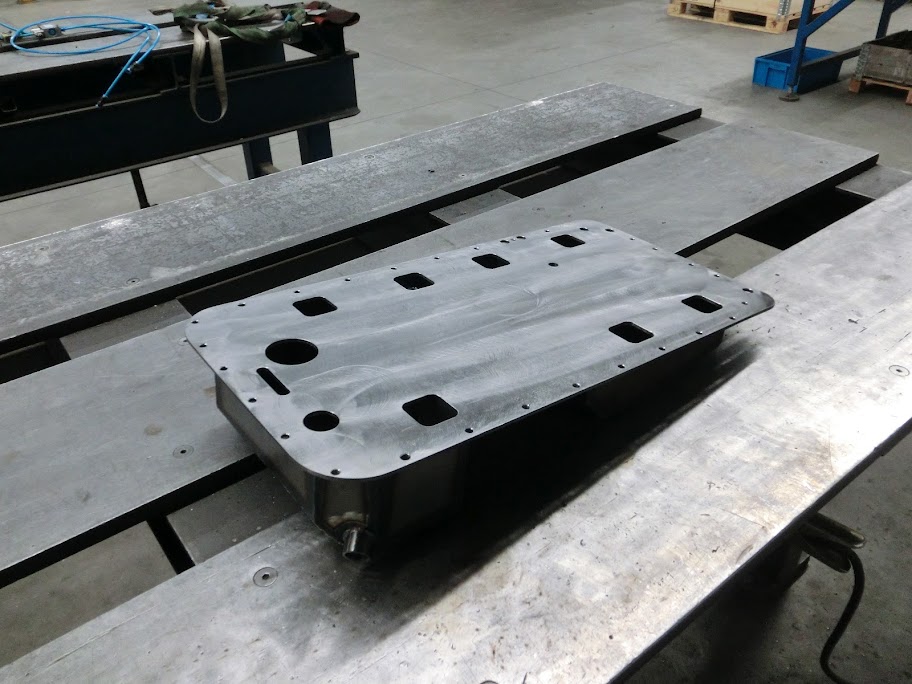
Oil-pan is finished for now.
I first made some fittings that hold a ball that acts like a check valve, and welded them in, you can actually see the check valve ***** if you look closely
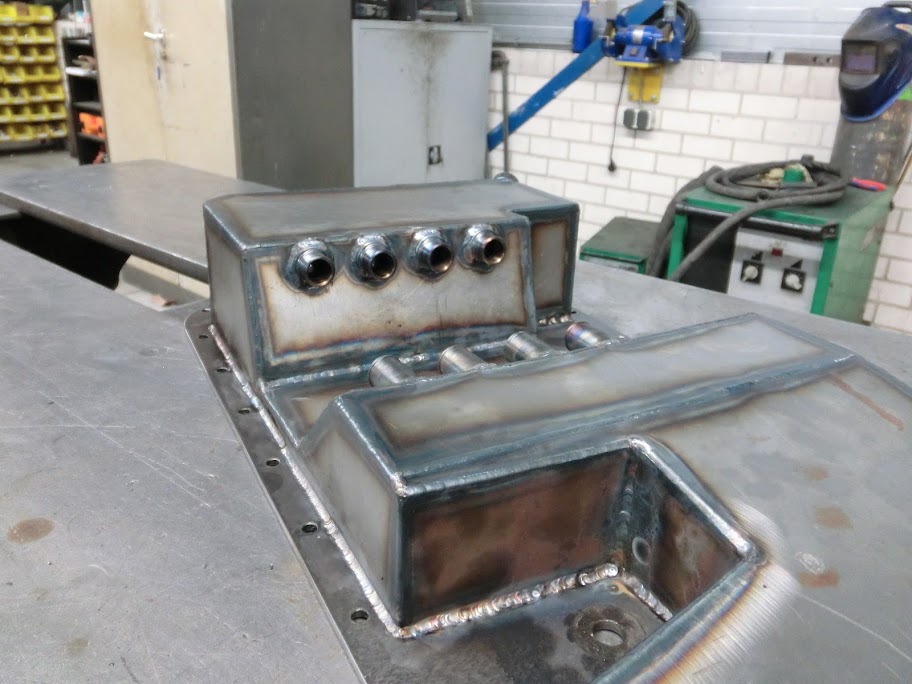
When all the welding was done I straightened the pan as much as I could, and then machined the mating surface perfectly flat. This should prevent any oil leaks.
Also started on my front pully, The stock hub and pully fits, but I wanted something smaller, more lightweight, better looking and with a different ratio. I ended up using a modified stock hub with a pully machined out of 7075 alloy attached to it. The triggerwheel I made will have threaded holes in it, then 4x M6 bolts will hold everything together. The pully is a bit smaller than normal, original waterpump / crankshaft ratio is 1.23, I'm using a 1.05 ratio.
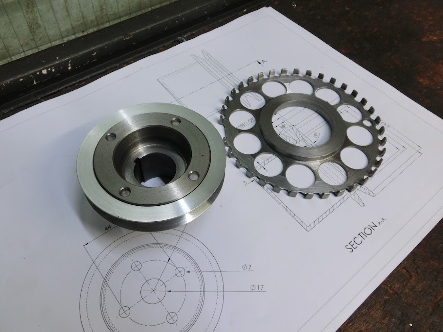

Next up are the waterpump and alternator pully's.
Also got some fuel stuff and found some nice engine mounting bushings. I wanted something stiffer and stronger than stock, but I didn't want to go with solid ones because I'm planning on using 4 engine mounts. 4 Solid mounts will cause stress in the engine. These are a nice compromise, and best of all, they only cost me $3 each.
Oil-pan is finished for now.
I first made some fittings that hold a ball that acts like a check valve, and welded them in, you can actually see the check valve ***** if you look closely
When all the welding was done I straightened the pan as much as I could, and then machined the mating surface perfectly flat. This should prevent any oil leaks.
Also started on my front pully, The stock hub and pully fits, but I wanted something smaller, more lightweight, better looking and with a different ratio. I ended up using a modified stock hub with a pully machined out of 7075 alloy attached to it. The triggerwheel I made will have threaded holes in it, then 4x M6 bolts will hold everything together. The pully is a bit smaller than normal, original waterpump / crankshaft ratio is 1.23, I'm using a 1.05 ratio.
Next up are the waterpump and alternator pully's.
Also got some fuel stuff and found some nice engine mounting bushings. I wanted something stiffer and stronger than stock, but I didn't want to go with solid ones because I'm planning on using 4 engine mounts. 4 Solid mounts will cause stress in the engine. These are a nice compromise, and best of all, they only cost me $3 each.
02-23-12, 01:28 AM
#367
7-Rex

Join Date: Jan 2012
Location: NJ
Posts: 94
Likes: 0
Received 0 Likes
on
0 Posts
I don't think i have seen something as tech as this. this is just pure genius einstein type of stuff good job keep the build going and you are probably the luckiest person to be able to do such a great thing.!

 02-23-12, 11:43 AM
#371
No, industrial vibration absorbers. These can take over 2200 pounds each, so I think 4 of these will be able to hold my engine
 . They have the same height as the stock ones, but are a bit larger in diameter which makes them stronger and stiffer. They mount the same way as the stock ones.
Bad news today by the way.
 The shop that's grinding my e-shaft called, saying the e-shaft bended a little bit over time, and they can't guarantee the shaft having the correct dimensions and stroke after grinding. I think I figured out a way to fix it though, but it's going to be extremely difficult. This is really crappy, because of the time and money which is already invested in the e-shaft. Nothing else to do but to do the very best I can and see how it will work out.
02-23-12, 03:00 PM
The shop that's grinding my e-shaft called, saying the e-shaft bended a little bit over time, and they can't guarantee the shaft having the correct dimensions and stroke after grinding. I think I figured out a way to fix it though, but it's going to be extremely difficult. This is really crappy, because of the time and money which is already invested in the e-shaft. Nothing else to do but to do the very best I can and see how it will work out.
02-23-12, 03:00 PM
#373
But, couldn't they bend the e-shaft back? My shop, that I havn't used yet though, said that they would be able to correct the e-shaft if it bends over time. They do repair old cranks also?
02-23-12, 03:41 PM
#374
Yes, they will bend the e-shaft back, the main problem is that they can't verify if the 15mm stroke is exactly correct within specifications. I believe it needs to be within 0.05mm (14.95mm-15.05mm), and they can't guarantee that it will turn out that way, because they align the grinding machine to the existing rotor lobe which is now bended. When they properly straighten the shaft it should be pretty close but since it's such an expensive piece they aren't willing to take the risk of it being out of spec. So they are going to straighten the shaft, then grind the main bearing surfaces. Then I'll pick the shaft up, put it in the measuring jig I made, check the stroke, and machine new reference surfaces if necessary so they can properly align the shaft. It should work, but the money and cost involved is piling up, and there's no certainty if I even end up with a true piece. I could just take the risk, let them grind it, put everything together and hope for the best, but if it doesn't work out a LOT of work and money would've been for nothing.
02-24-12, 12:26 AM
#375
Sucks to hear about the e shaft. But to be honest, IMHO, I would think you sort of have to expect and plan for bumps like this when you take on full fab project of this scope. But you don't have to defend that when crap happens, it still sucks and costs money you'd hoped to not have spent.
If it was me, I wouldn't risk damaging all the other fine pieces you've machined. Not to mention no one would want to see me destroy perfectly good housings and irons
If it was me, I wouldn't risk damaging all the other fine pieces you've machined. Not to mention no one would want to see me destroy perfectly good housings and irons