4-Rotor FC Build
 12-25-11, 10:40 AM
#201
The nitrating is about 0,6mm's deep, but hardness varies, it's the hardest at the surface. I left about 0,2mm's of material for grinding, so the main bearing surfaces that are going to be 42,99mm's in diameter are now 43,4mm's. Leaving less material is risky, because any inaccuracies will make it impossible to grind the shaft to perfect size.
Next job is fixing the center stat gear in place. I did some more machining to it, and pressed it into place. Need to finetune the position of the gear, then I can drill and tap 12 holes where M8 setscrews will be inserted.
Note the main bearings in there, there are 2 that are both machined down to make them shorter.

Last edited by John Huijben; 12-25-11 at 10:44 AM.
 12-27-11, 05:02 PM
#202
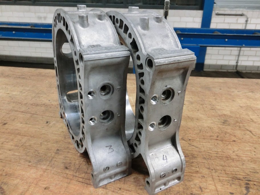
Numbered the rotor housings today

Not as simple as you might think, I noticed that the rotors all were a little bit different. When you randomly put a rotor in an rotor housing the clearances weren't always ok.
There should be between 0.4 and 0.7mm's of space between the rotor and the housing on each side, and I got like 0.3mm's at one side and 0.6mm's at the other side if I put everything back together the way it was when I disassembled the engines. So i mixed and matched some rotors with some housings, and got the sets matched, so that's good. When I knew the rotor clearances in the housing were ok it was time to fix the center stationairy gear in the center iron.

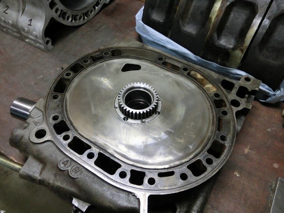

There are 5x M8 setscrews on each side, so 10 screws in total that keep everything together. There are 3x 7.5mm holes on each side to drain oil back into the sump. 2 are located on each side of the stat gear, and one is located at the bottom side. Getting oil out of the engine is just as important as getting the oil in
Next job, sandblasting, filling and painting the irons. Don't know if I'll go with regular black or grey iron's or something more flashy like red or something, any ideas?
Also need to order some material so I can machine some longer tension bolts.
Not as simple as you might think, I noticed that the rotors all were a little bit different. When you randomly put a rotor in an rotor housing the clearances weren't always ok.
There should be between 0.4 and 0.7mm's of space between the rotor and the housing on each side, and I got like 0.3mm's at one side and 0.6mm's at the other side if I put everything back together the way it was when I disassembled the engines. So i mixed and matched some rotors with some housings, and got the sets matched, so that's good. When I knew the rotor clearances in the housing were ok it was time to fix the center stationairy gear in the center iron.
There are 5x M8 setscrews on each side, so 10 screws in total that keep everything together. There are 3x 7.5mm holes on each side to drain oil back into the sump. 2 are located on each side of the stat gear, and one is located at the bottom side. Getting oil out of the engine is just as important as getting the oil in
Next job, sandblasting, filling and painting the irons. Don't know if I'll go with regular black or grey iron's or something more flashy like red or something, any ideas?
Also need to order some material so I can machine some longer tension bolts.
12-29-11, 12:20 AM
#205
Rotary Enthusiast
iTrader: (2)
Join Date: May 2005
Location: E-L Netherlands
Posts: 1,165
Likes: 0
Received 0 Likes
on
0 Posts
NI think you should also think about what you want to do with the body. i would choose a combo that wont stand out too much compared to it.
So if it stays red, i would also say to use red
So if it stays red, i would also say to use red
12-29-11, 10:03 AM
#207
.I ditched the red TII chassis, and am going to use a grey n/a chassis. Planning on doing as little work to the chassis as possible untill the engine is running succesfully.
12-29-11, 04:37 PM
#208
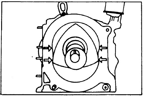
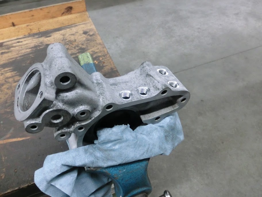
Ready to insert the tube that supplies oil to the center of the engine

Still need to make that tube though, I'd like to use brass because it's softer and will seal better. Didn't have any brass though so I'll order some and make it later. It's going to look a lot like this though
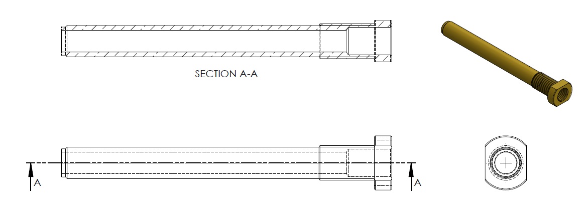
Still need to make that tube though, I'd like to use brass because it's softer and will seal better. Didn't have any brass though so I'll order some and make it later. It's going to look a lot like this though
12-31-11, 04:43 AM
#211
Yep, Solidworks 2012. It's what I've got at work Pretty good though, I've also worked with different software like Inventor, Hicad and Autocad but I like Solidworks.
You mean for the stress analysis? Mostly I use the default ffeplus solver that's default in solidworks simulation. It's just easy to use on parts like the e-shaft and such. I've used different solvers when the model requires it. Like a while ago I did an analysis of a kit-car frame for an english kitcar manufacturer. Because of the model, which is a tubed frame I had to use a different solver.

Pretty good though, I've also worked with different software like Inventor, Hicad and Autocad but I like Solidworks.
01-03-12, 05:47 PM
#213
Did a little bit more work to it. Planned on doing a lot of small things to it after work, but ended up only doing a few  , Didn't botch anything up though so that's good.
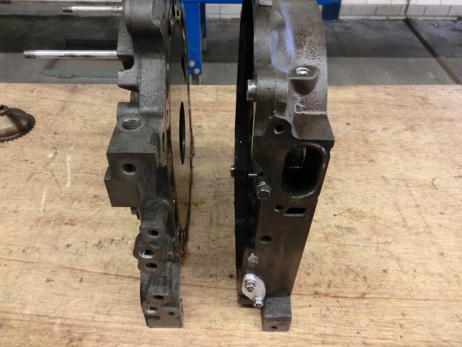
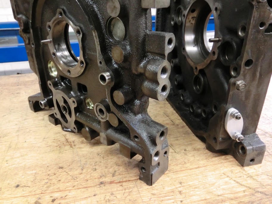
Main stuff I did was closing off some connections. Closed off the turbo oil return hole, a coolant nipple on the rear iron, and the oil pressure sensor hole. Closing off that last one off isn't normally necessary but the previous owner of the iron thought it was a good idea to use the oil pressure sensor as an lifting point to hoist the engine out. It wasn't. A small corner of the iron casting chipped off, so I machined it flat, tapped in some more thread and sealed it. I'll find another more accessible spot for that sensor to go.
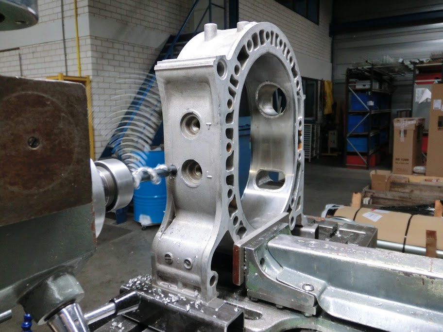
After I was done closing off stuff I added some stuff. I added 2 threaded holes in the front iron. One for feeding the front stationairy gear with oil, which normally goes through the engine dowels and some 90� bends to the front of the engine. I don't think that's a good idea with a 4-rotor because of the engine length and all, so I drilled a hole and tapped in some 1/4" BSP thread for a loopline to go.
The other one is directly connected to the oilpump output. The main reason I did that is because I'm planning to run dual fc oil coolers in parallel, and this simplifies plumbing, because I can run one line from the original oil line spot to one oil cooler, and one line from the added connection in the side of the front iron to the second oil cooler. Did take me a while to add these holes though. The casting is pretty thin and I didn't want to crack the iron or anything so I took my time.
Some pictures:
I'd better be carefull when connecting the oillines, this can get confusing
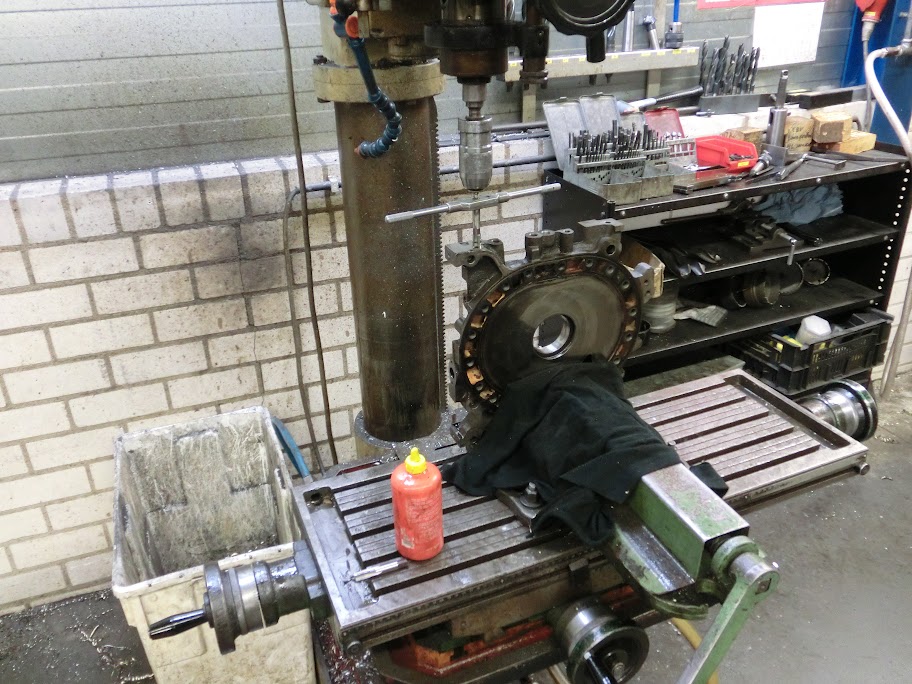
Tapping here, The drill chuck has a piece in it that fits into the top of the tap, this keeps the tap straight. I also used a set of 2 taps to keep the pressure on the brittle cast iron down.
Yep, but the separate "Solidworks Flow Simulation" package, not that floxpress that comes with a standard installation.
, Didn't botch anything up though so that's good. Main stuff I did was closing off some connections. Closed off the turbo oil return hole, a coolant nipple on the rear iron, and the oil pressure sensor hole. Closing off that last one off isn't normally necessary but the previous owner of the iron thought it was a good idea to use the oil pressure sensor as an lifting point to hoist the engine out. It wasn't. A small corner of the iron casting chipped off, so I machined it flat, tapped in some more thread and sealed it. I'll find another more accessible spot for that sensor to go.
After I was done closing off stuff I added some stuff.
I added 2 threaded holes in the front iron. One for feeding the front stationairy gear with oil, which normally goes through the engine dowels and some 90� bends to the front of the engine. I don't think that's a good idea with a 4-rotor because of the engine length and all, so I drilled a hole and tapped in some 1/4" BSP thread for a loopline to go.The other one is directly connected to the oilpump output. The main reason I did that is because I'm planning to run dual fc oil coolers in parallel, and this simplifies plumbing, because I can run one line from the original oil line spot to one oil cooler, and one line from the added connection in the side of the front iron to the second oil cooler. Did take me a while to add these holes though. The casting is pretty thin and I didn't want to crack the iron or anything so I took my time.
Some pictures:
I'd better be carefull when connecting the oillines, this can get confusing
Tapping here, The drill chuck has a piece in it that fits into the top of the tap, this keeps the tap straight. I also used a set of 2 taps to keep the pressure on the brittle cast iron down.
Yep, but the separate "Solidworks Flow Simulation" package, not that floxpress that comes with a standard installation.
 01-04-12, 03:30 PM
#215
Nice fix for your oil pressure hole.
Your coolant tube looks different. Did you make it?
R5 rear irons don't have a threaded oil pressure hole so I bolt the plate to the drill press, drill, then tap with the drive belts disconnected. I can only get a couple threads in before it gets too hard to turn the chuck by hand. I don't have a nifty adjustable hand crank like that.
01-04-12, 11:46 PM
#216
Seth
01-05-12, 03:58 PM
#219
I'm not very familiar with the Solidworks internal CFD solver. What does the flow simulation package have that the other does not? Does it include some turbulence models and other solution methods/goodies that the standard one doesn't? Or does it just increase the maximum element count?
Seth
Seth
But no I'm not going to use it, can't see why I would like to do that since I'm planning to use this car on the streets.
, It's a holset hx55 (22cm^2 housing I believe). But yeah I'd probably need 2 of these for this engine  01-07-12, 01:41 PM
#220
Did some more work today,
First I cleaned the iron's thouroughly, I'm going to wait with painting them though untill the engine is ready to be assembled. Also made some plugs and sealed off the primary injector spots. Not really nessacary because the runners are going to be filled anyway, but it looks tidier this way.
When that was done I added some fittings that will allow me to route coolant from the waterpump to the #3 and #4 rotor housings to even out the coolant temperatures.
Machined 4x 1/4" threaded holes in there, Don't do it like this if your planning on using your alternator in the original position, I'm planning to side mount it since I don't have any power steering
Also made threaded holes in the rotor housings
Fitted some stuff together
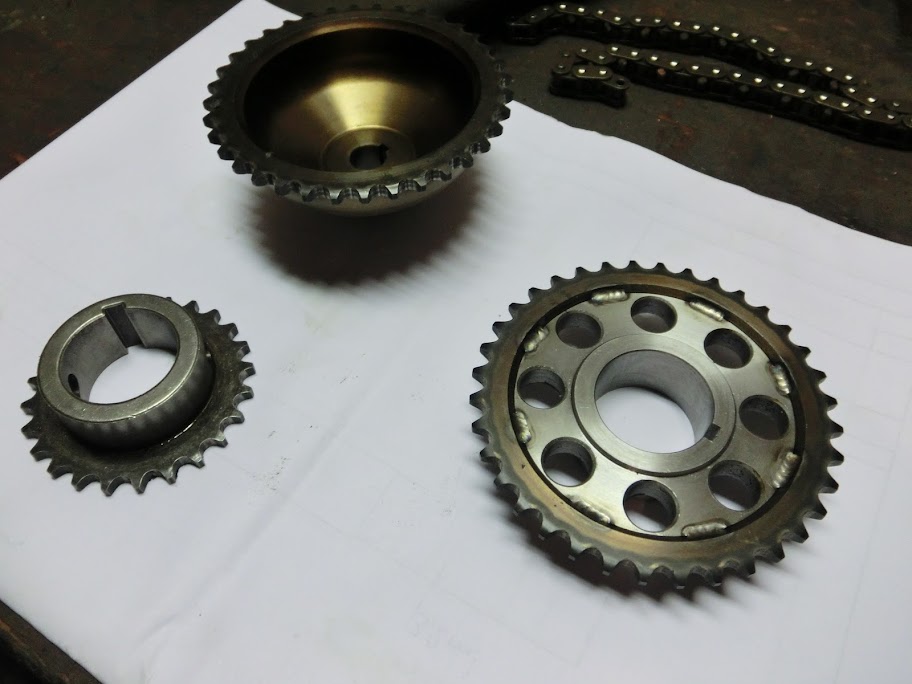
Also made an oil pump drive sprocket. This raises the oil pump speed to increase the output flow. I machined the center out of a large oil pump sprocket and machined a hub. Then heated the sprocket, pressed it over the the hub and tig-welded 16 small spots.
The final part basically has the outside of the top sprocket and the inside of the bottom sprocket.
I'll mock the front end of the engine up tomorrow so I can see if everything fits properly and see if I can assemble a chain for it.
First I cleaned the iron's thouroughly, I'm going to wait with painting them though untill the engine is ready to be assembled. Also made some plugs and sealed off the primary injector spots. Not really nessacary because the runners are going to be filled anyway, but it looks tidier this way.
When that was done I added some fittings that will allow me to route coolant from the waterpump to the #3 and #4 rotor housings to even out the coolant temperatures.
Machined 4x 1/4" threaded holes in there, Don't do it like this if your planning on using your alternator in the original position, I'm planning to side mount it since I don't have any power steering
Also made threaded holes in the rotor housings
Fitted some stuff together
Also made an oil pump drive sprocket. This raises the oil pump speed to increase the output flow. I machined the center out of a large oil pump sprocket and machined a hub. Then heated the sprocket, pressed it over the the hub and tig-welded 16 small spots.
The final part basically has the outside of the top sprocket and the inside of the bottom sprocket.
I'll mock the front end of the engine up tomorrow so I can see if everything fits properly and see if I can assemble a chain for it.
 01-08-12, 03:50 PM
#222
Because I modified the the oil pump drive gear to be larger the chain had to be lenghtened by 3 links.
So made a longer chain out of 2 regular chains, because mazda uses an odd pitch that I couldn't find.
After that I assembled the front part of the engine using some parts I had lying around and checked the slack.
Oh crap... almost an inch of slack, I think I'll need a chain tensioner

[/img]
So made a longer chain out of 2 regular chains, because mazda uses an odd pitch that I couldn't find.
After that I assembled the front part of the engine using some parts I had lying around and checked the slack.
Oh crap... almost an inch of slack, I think I'll need a chain tensioner
[/img]
01-08-12, 07:46 PM
#223

idea
Hey mate awesome build. Im not saying you dont already know but its a problem i ran into with my 26b build. When you increase the oil pump sprocket to that size if you dont have the right front cover it will hit it. You probably have already thought of this judging by your awesome build so far i love it. I like your coolant idea. Any reason why you didnt just go electric with the water pump? Keep up the awesome work
01-09-12, 01:26 AM
#224
Yes I know about that, but it's really close to fitting so I'll probably be able to machine out the front cover a bit to make it fit without welding or anything. But i can weld a piece in there if I have to. But if you tried the same oil pump setup as me you've also encountered the problem that there is too much slack in the chain, how did you solve that? I don't want to use an electric waterpump if I don't have to because of space issues or anything. I don't think one of those will pump more than the 2nd gen one will, maybe at low rpms. If Im going to need one I will, but Im trying the 2nd gen pump first.
01-09-12, 09:11 AM
#225
i can see the light!!!
Join Date: Jul 2008
Location: Richmond, VA.
Posts: 165
Likes: 0
Received 0 Likes
on
0 Posts
This build is awesome... I have pondered a four rotor for years and my only issue thus far is whether to buy all the parts or have them made from scratch as you have done. I congradulate you on the incredible amount of work you have done thus far. I am subscribed for life!!