4-Rotor FC Build
 01-25-12, 11:52 PM
#276

 01-29-12, 01:51 PM
#277
Sure thing, just let me catch up on my swedish first 
Anyways, more work has been done to the 4-rotor in the last couple of days.
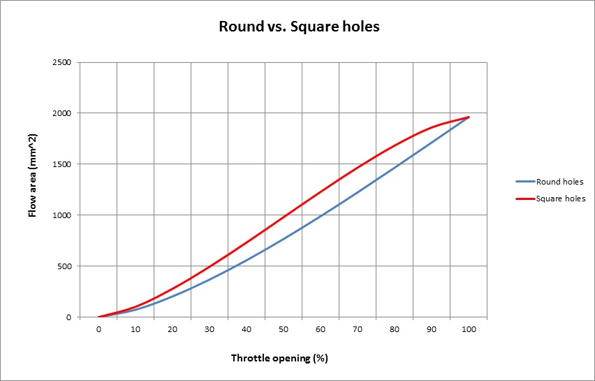
First thing I did was finish the slide throttle.
All the parts

The sensor works with a moving tab, I was worried that the hole in the teflon would enlargen over time, so I made a steel insert that's pressed into the teflon. The sensor tab precisely fits into that insert. It's more wear resitant this way, and only was a 10min job

Some small stainless parts
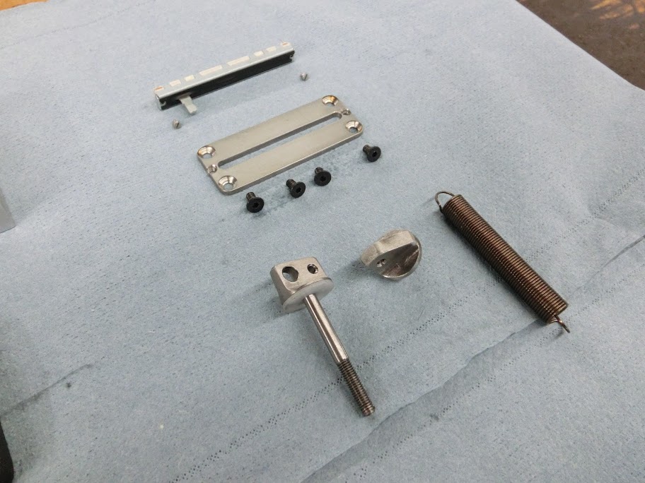
This is how the sensor fits, it's mounted from the inside because the outside will be blocked off. That extruding tab fits into the steel insert in the throttle slide
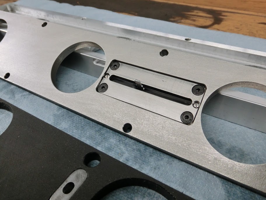
And assembled, moves back and forth nicely
Next job I had was to change the studs in the front iron. This is because I'm using an S4 waterpump on an S6 iron. It fits but the S4 uses shorter studs, so I swapped them over.

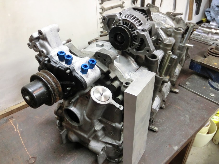
Also made the engine dowel pins and tension bolts. Both are made from steel similar to 4140. The dowel pins are solid, because I'm doing the oillines externally. They are ground to spec and I machined the ends to size. The tension bolts started as normal 10mm roundbar, I added boltheads to them. I've just threaded the end of every roundbar and screwed an M10 nut on there untill it jammed. After that I heated the roundbar and nut untill it started to glow red and then welded the nut to the roundbar using 309 wire. When that was done I machined the M10x1 thread onto the other end. Repeat that 18 times, and done Total manufacturing costs for the dowel pins and the tension bolts was around $90

Couldn't resist mocking everything up to see how it fits. Fits together perfectly
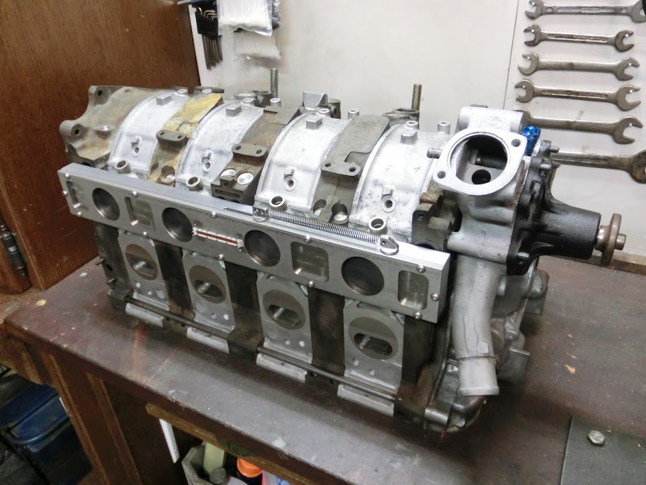
Next up is the fuel rail, alternator mount and oilpan.
Also continued working on the dyno. It's working pretty good at the moment, we're just ironing out the last details, mostly software problems. We had a scary moment a few days ago. We were doing some runs with a car, and right when the car was going around 140 one of the cooling fans shorted out and we lost all electricity. So there we were in the pitch dark with a car going that fast on the dyno. Rolled the car to a stop and got everything up and running in notime though.

Anyways, more work has been done to the 4-rotor in the last couple of days.
First thing I did was finish the slide throttle.
All the parts
The sensor works with a moving tab, I was worried that the hole in the teflon would enlargen over time, so I made a steel insert that's pressed into the teflon. The sensor tab precisely fits into that insert. It's more wear resitant this way, and only was a 10min job
Some small stainless parts
This is how the sensor fits, it's mounted from the inside because the outside will be blocked off. That extruding tab fits into the steel insert in the throttle slide
And assembled, moves back and forth nicely
Next job I had was to change the studs in the front iron. This is because I'm using an S4 waterpump on an S6 iron. It fits but the S4 uses shorter studs, so I swapped them over.
Also made the engine dowel pins and tension bolts. Both are made from steel similar to 4140. The dowel pins are solid, because I'm doing the oillines externally. They are ground to spec and I machined the ends to size. The tension bolts started as normal 10mm roundbar, I added boltheads to them. I've just threaded the end of every roundbar and screwed an M10 nut on there untill it jammed. After that I heated the roundbar and nut untill it started to glow red and then welded the nut to the roundbar using 309 wire. When that was done I machined the M10x1 thread onto the other end. Repeat that 18 times, and done
Total manufacturing costs for the dowel pins and the tension bolts was around $90Couldn't resist mocking everything up to see how it fits. Fits together perfectly
Next up is the fuel rail, alternator mount and oilpan.
Also continued working on the dyno. It's working pretty good at the moment, we're just ironing out the last details, mostly software problems. We had a scary moment a few days ago. We were doing some runs with a car, and right when the car was going around 140 one of the cooling fans shorted out and we lost all electricity. So there we were in the pitch dark with a car going that fast on the dyno. Rolled the car to a stop and got everything up and running in notime though.
 01-30-12, 03:31 AM
#283
I'm thinking battery powered emergency light
Haha no, someone asked for a dyno picture a while ago, the VW just happened to be on there. The 4-rotor is going into an FC. nothing really fancy, just an S4 chassis with tein suspension, ssr wheels and a TII driveline. The car is currently stored, I'm planning to bring it over in a few weeks so I can mount the mockup engine in there and get started on the exhaust, intake and cooling systems.
Haha no, someone asked for a dyno picture a while ago, the VW just happened to be on there. The 4-rotor is going into an FC. nothing really fancy, just an S4 chassis with tein suspension, ssr wheels and a TII driveline. The car is currently stored, I'm planning to bring it over in a few weeks so I can mount the mockup engine in there and get started on the exhaust, intake and cooling systems.
01-30-12, 04:45 AM
#284
This is my social media.
iTrader: (22)
Join Date: Jan 2006
Location: WA
Posts: 2,744
Likes: 0
Received 0 Likes
on
0 Posts
I liked the car you had before... I'm curious to see this next car you've chosen to be "The One". Heh'
 01-30-12, 01:34 PM
#288
Picture of the shell I'm going to be using, sorry for the lousy picture, I'll make some better ones when the car gets out of storage.
Currently looking how to get the alternator mounted. I can't side mount it neatly because the oil looplines are in the way. I'm thinking about mounting it just above the normal turbo oil feed spot. This way the oil looplines and the water looplines both clear. I'll make a bracket out of 6060 alloy, and make a tensioner between the original alternator mount and the new alternator.
Also trying to figure out how to do my alternator and water pump belt drive. I can probably modify the stock pully's to work, but I'm thinking about machining some custom lightweight underdrive pully's, or a gilmer setup. Sortoff leaning towards a gilmer setup. What do you think?
 01-30-12, 03:19 PM
#291
Ahhh right, makes sense! Don't know why I was thinking about the eccentric shaft nut there 
Anyway, I don't see a huge benefit in using nuts to tighten the tension bolts. The coarse M10 threads I used for the 'bolthead' nuts are unsuitable because you'll need a fine thread. I could have cut a fine thread onto there and use special nuts, but I don't see a really huge benefit in that. Maybe if you use oversize 12.7mm studs. One other thing to concider is that I'm using machined threads instead of rolled ones which are a little bit weaker. The front iron has around 15mm's of thread that I use, nuts are shallower so you use less thread. This would increase the chance of the thread stripping off when tightening.
Fair point, but a custom gilmer setup which uses a 1" wide belt doesn't have to be a whole lot wider than normal. Should be shallower than a double sheave pully.
01-30-12, 03:21 PM
#292
Moderator
iTrader: (3)
Join Date: Mar 2001
Location: https://www2.mazda.com/en/100th/
Posts: 30,826
Received 2,593 Likes
on
1,842 Posts
i wanted to do it with mine, the alternator moves down, which is good. it also makes the stock belt routing over the water pump better. and it moves to the right, which is the light side of the car, so if it fits there is no downside.
01-30-12, 06:16 PM
#293
This is great! ....ever heard of raising rotor compression or making end and intermediate housing like new.
http://jhbperformance.com/services.php
Check them out. I know at one point I had "the best rotary build" idea in my head and this was part of it.
http://jhbperformance.com/services.php
Check them out. I know at one point I had "the best rotary build" idea in my head and this was part of it.
01-31-12, 10:56 AM
#297
i guess some people don't realize there are shops that already make 4 rotor kits. but you know the old saying "if you gotta ask, you probably can't afford it". most 4 rotors will be neck deep about $30-40k before thinking about turning the ignition key.
 01-31-12, 02:32 PM
#299
Rotary Enthusiast
godverdomme , waar in nederland ben jij precies
waneer denk jij dat dit klaar is ....ongeloovelijk spul man
heb je ooit gedacht om aluminium rotors te maken ?
top werk man !!
waneer denk jij dat dit klaar is ....ongeloovelijk spul man
heb je ooit gedacht om aluminium rotors te maken ?
top werk man !!