4-Rotor FC Build
 01-31-12, 05:40 PM
#301
how about putting the alternator where the air pump used to be? depending on the throttle body it might fit.
i wanted to do it with mine, the alternator moves down, which is good. it also makes the stock belt routing over the water pump better. and it moves to the right, which is the light side of the car, so if it fits there is no downside.
i wanted to do it with mine, the alternator moves down, which is good. it also makes the stock belt routing over the water pump better. and it moves to the right, which is the light side of the car, so if it fits there is no downside.
Update
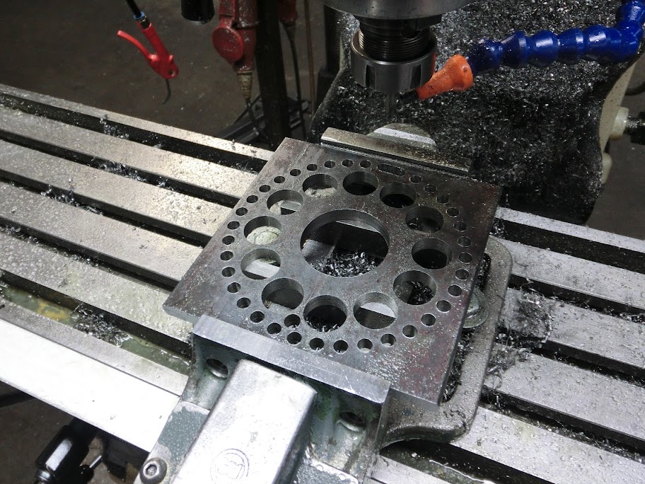
Started on the alternator bracket. Mocked some stuff up a few days ago, found a spot that might work and a piece of 6060 alloy and started machining it today.
2,5 pounds of aluminium
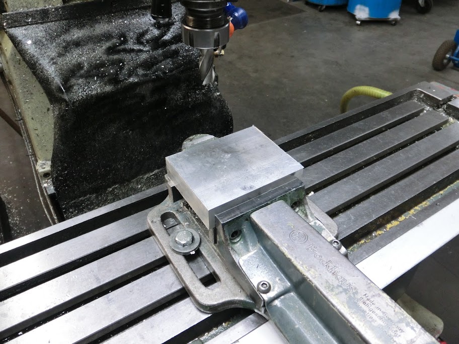
Machining the bottom side here, looks goofy right now but it makes sense when bolted to the engine
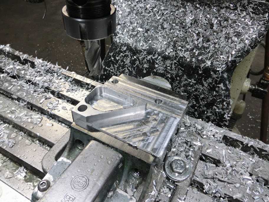
Finished machining the bracket, total machining time was about 2,5 hours. Quickly mounted it to see how everything fits. Still needs some teflon pivoting inserts, and a tensioner.
The tensioner will be made from 2 rod end bearings and a piece of rod, and will go between the stock alternator mounting point on the waterpump and that point on the current alternator
Outside part of the bracket, I'm a little bummed about the thin wall thickness in the stiffening rib in the upper left corner. I should really model these things out on the computer before machining.
 It's still more than strong enough though, the bottom of the bracket is about 5mm's thick, so the bracket will hold even without the ribs
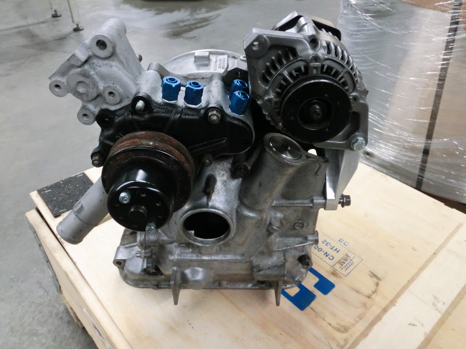
Had to remove a piece from the front iron to make the alternator fit nice and snug. I didn't remove the entire mounting point though, those boltholes might come in handy some day


 01-31-12, 07:15 PM
#303
Don't worry, Be happy
Join Date: Sep 2010
Location: where the fish fly and the birds swim, (Ga)
Posts: 166
Likes: 0
Received 0 Likes
on
0 Posts
Just seeing if there was going to be another 4rotor kit on the market. I can't afford something like this for a loooong time, but it's still interesting to find new things in the rotary market!
and if you don't mind me asking: since you're making everything your self has this been a lot cheaper than just buying a kit?
02-01-12, 07:52 AM
#305
Junior Member
Hi,
Wow! you are really good and not scared to share info at all.
I really like the quality workmanship.
Keep up the good work, and I am very eager to see/hear the end result.
The Netherlands is about to change.........
Regards
Adin
Wow! you are really good and not scared to share info at all.
I really like the quality workmanship.
Keep up the good work, and I am very eager to see/hear the end result.
The Netherlands is about to change.........
Regards
Adin
02-01-12, 10:26 AM
#307
Rotary Enthusiast
iTrader: (2)
Join Date: May 2005
Location: E-L Netherlands
Posts: 1,165
Likes: 0
Received 0 Likes
on
0 Posts

I think 1/2 - 3/4 of the price of all existing kits is to earn back the R&D, because time is money...
02-01-12, 12:41 PM
#308
inevitably we all have something to learn from one another to progress even faster.
i doubt John even really thinks this is revolutionary work, it is just his daily routine machining processes. just this time based around a rotary engine to double the size of the engine. the eccentric shaft being the key component and i doubt he even wants to tally up how many hours that has taken so far, heh. this and tegheim's have just been the only most well documented for the steps involved and the trials and errors along the way.
i'm sure i will also go over my build once i find the time to do anything with it for the more cost effective approach of modifying 2 stock shafts, granted it will not be able to handle as much power.
Last edited by RotaryEvolution; 02-01-12 at 12:49 PM.
02-02-12, 05:02 PM
#309
there's plenty of builders on here but we're beyond the point of trying to keep everything secretive. the only things that are kept under wraps are some specifics on builds for some of the top performing cars.
inevitably we all have something to learn from one another to progress even faster.
i doubt John even really thinks this is revolutionary work, it is just his daily routine machining processes. just this time based around a rotary engine to double the size of the engine. the eccentric shaft being the key component and i doubt he even wants to tally up how many hours that has taken so far, heh. this and tegheim's have just been the only most well documented for the steps involved and the trials and errors along the way.
i'm sure i will also go over my build once i find the time to do anything with it for the more cost effective approach of modifying 2 stock shafts, granted it will not be able to handle as much power.

Your not entirely right about my daily routine machining processes though
 I'm not a machinist for a living. I design automation systems behind a desk and help out in the workshop when needed. Most machined parts are outsourced these days, but we have a few manual machines at the shop so we can make some modifications if needed, or for when we quickly need a spacer or something. Imagine the puzzled look of my co-workers when I showed them the e-shaft I made on our own machines
 Update
Added some delrin bushings to mount the alternator
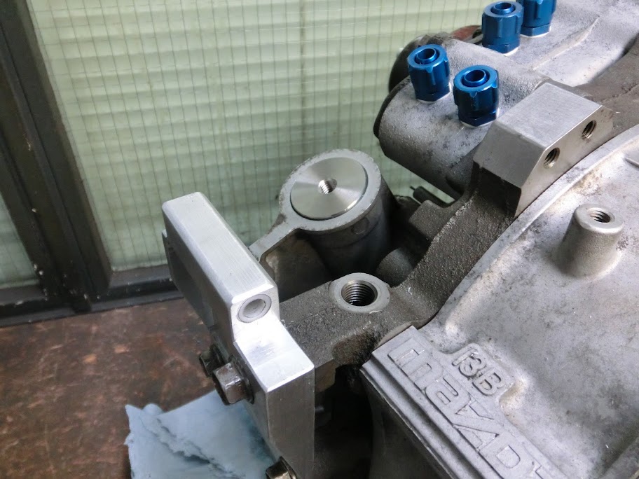
Also made a tensioner for it. One side of that rod has a normal thread, the other side uses a left hand thread. The middle of the rod has 2 flat parts where a 10mm socket fits onto. Turn the rod and the belt gets tensioned. It can then be locked by that nut. Didn't have a locking nut for the other end of the rod lying around, I'll get one tomorrow. All made from 304 stainless steel.
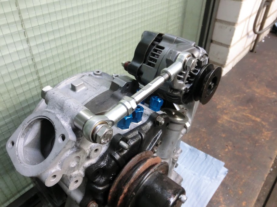
Front view

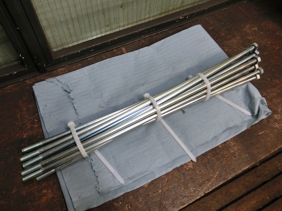
Got my tension bolts zinc plated so they won't rust.
And picked up a nice small VR-sensor. I'm planning to machine a custom front pully that also acts as a triggerwheel. I just got a generic GM sensor that's small and easy to get. I'm going to use a normal V-belt by the way with custom machined aluminium pully's. Should be a clean and lightweight setup when done.
02-04-12, 03:25 PM
#312

Update
Made the fuel rail today. It's a simple piece that consists out of a piece of pipe, some injector bungs and a few mounting brackets. Not as simple to make though, I made it from pretty thinwalled stainless steel, which loves to bend when it gets welded, and since the injector bungs have to be welded all the way around to not leak quite a bit of welding is necessary. Got it pretty good though, fits like a charm. I heard stories about fuel leaking between the injector bungs and the injectors with some aftermarket rails, so I made those holes a few thousands smaller. The bungs in the rotor housings were done the same. The injectors fit snugly but you can still rotate them without a lot of effort when everything is mounted.
Some parts, bungs were machined on the lathe, the holes in the rail were actually machined on the mill. Plain drilling leaves nasty edges on the inside of the rail, this doesn't happen when using a good endmill

Tacked the bungs to the rail, time for test fitting on the mocked up engine

Everything fitted well, so I welded everything together and added some mounting brackets. The brackets need to be pretty strong, when fuel pressure is 70 psi there's about 65 pounds of force trying to lift the fuel rail. I still need to weld fittings to it, but I don't know which ones I'm going to use yet
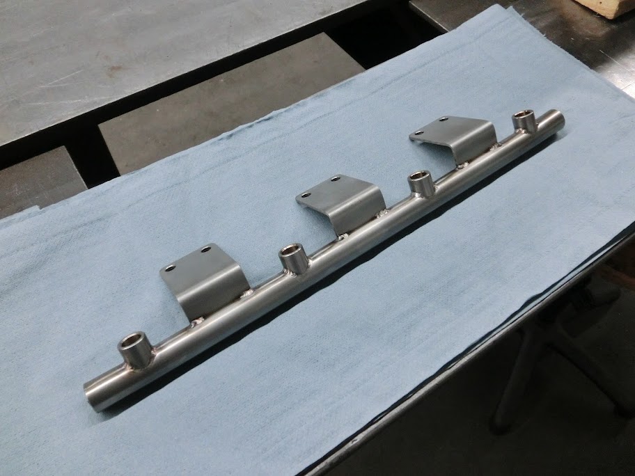

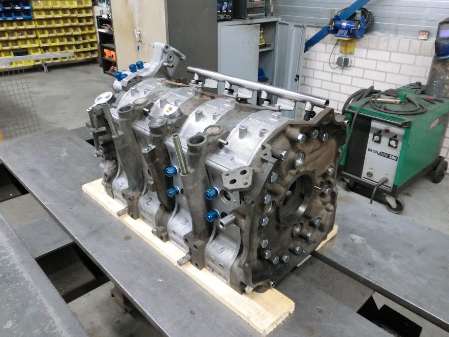
Fits well, those are ID1000 injectors

Also started on measuring out the oilpan

Need to mockup a subframe with the engine before I can finish the model and start making it but I can't get to my spare parts because there's 5 inches of snow outside
 .
. Also got my OS giken twin plate clutch, looks like it will work
I'll make some pictures soon
02-04-12, 03:49 PM
#313
i love your updates, what gearbox are you going to use? i dont remember if you said any thing on the matter?
are you going to go all out on the engineering on the fc as well? like a roll cage, chassie strenghting and suspension? things along those lines?
are you going to go all out on the engineering on the fc as well? like a roll cage, chassie strenghting and suspension? things along those lines?
02-05-12, 05:02 PM
#317
the front iron would see less stress with the alternator mounted like that, it was actually more stress on the front iron with it mounted in the stock location.
i'm curious about your sump system with the stock pump. i figured i would run a sump tank to gravity feed to the pickup and to eliminate aeration of the oil with an auxiliary pump to push the oil to the tank from the returns. i remember you picked up a mechanical pump and i suppose that is it's purpose? or is the internal pump to pump it to the surge tank then the auxiliary pump takes over from there?
i'm curious about your sump system with the stock pump. i figured i would run a sump tank to gravity feed to the pickup and to eliminate aeration of the oil with an auxiliary pump to push the oil to the tank from the returns. i remember you picked up a mechanical pump and i suppose that is it's purpose? or is the internal pump to pump it to the surge tank then the auxiliary pump takes over from there?
Last edited by RotaryEvolution; 02-05-12 at 05:07 PM.
02-05-12, 06:37 PM
#318
I don't believe I have subscribed to this thread yet because I haven't had to with how hard you have been working on this project there have been plenty of updates. You really seem to be making good use of you're talent. Looking forward to whats to come. Subscribed.
 02-06-12, 03:01 PM
#321
i would also probably make another brace from the base of the rail mounts to the top of the rail, the mounts usually are pretty flimsy so it will move around some and why some rails tend to leak. this is usually a boosted motor issue or with cars running much higher than the typical 40psi of rail pressure. on those cars i have to shim the injectors so tight that they can't move, i've seen plenty of injectors leak even below 20psi of boost running 60psi line fuel pressure because the injectors tend to bob up and down.
02-06-12, 05:18 PM
#324
the front iron would see less stress with the alternator mounted like that, it was actually more stress on the front iron with it mounted in the stock location.
i'm curious about your sump system with the stock pump. i figured i would run a sump tank to gravity feed to the pickup and to eliminate aeration of the oil with an auxiliary pump to push the oil to the tank from the returns. i remember you picked up a mechanical pump and i suppose that is it's purpose? or is the internal pump to pump it to the surge tank then the auxiliary pump takes over from there?
i'm curious about your sump system with the stock pump. i figured i would run a sump tank to gravity feed to the pickup and to eliminate aeration of the oil with an auxiliary pump to push the oil to the tank from the returns. i remember you picked up a mechanical pump and i suppose that is it's purpose? or is the internal pump to pump it to the surge tank then the auxiliary pump takes over from there?
i would also probably make another brace from the base of the rail mounts to the top of the rail, the mounts usually are pretty flimsy so it will move around some and why some rails tend to leak. this is usually a boosted motor issue or with cars running much higher than the typical 40psi of rail pressure. on those cars i have to shim the injectors so tight that they can't move, i've seen plenty of injectors leak even below 20psi of boost running 60psi line fuel pressure because the injectors tend to bob up and down.
Update
I needed a triggerwheel for this engine, you can buy them pretty cheap, but I couldn't find one with the dimensions I wanted. Someone smart would've get one waterjetted and be done with it. But the machines were empty and I had some material lying around so I figured why not give it a shot myself.
Drilling, this really wasn't fun at all
And all machined up

Still need to deburr and paint it but I think it will work. It fits onto the pully hub together with the front pully. Already ordered material for the pully's by the way, aircraft grade aluminium
 02-06-12, 05:25 PM
#325
Senior Member
Mmmh is it just me or is the middle plate an other plate. The intake is higher then the rest.
@ts: why you don't change the front so you can run drysump, can be that hard if you make your own two piece excentric axle.
Oeeeh nice trigger wheel, but I miss something, jup the space out (or how you call it) for the TDC of rotor 1
@ts: why you don't change the front so you can run drysump, can be that hard if you make your own two piece excentric axle.
Oeeeh nice trigger wheel, but I miss something, jup the space out (or how you call it) for the TDC of rotor 1
Last edited by damic; 02-06-12 at 05:28 PM. Reason: trigger wheel