Kilo Racing 3 Rotor FD Conversion
 09-21-09, 10:20 AM
#3226
Carlo, the theory here is my temps are fine but due to where the sensor is located (one inch from the turbo) I am getting false readings. This would be true whether I use the controller or dash or even if I go with your mod.
The mechanic that noticed this was using a laser thermal temp gun and he found the temps under the hood never went above 195 or so which would put the car at 92 C which is where the fans come on.
Because of where the PLX sensor is located, the readings on the gauge were much higher and this is what I am trying to fix.
Could all turn out to be nothing and maybe I have a temp problem, but I would like to solve the sensor location first and go from there.
i dont know where your sensor is but mine is right behind my water pump and i tried putting it somewhere else it was the same stuff.
 09-22-09, 07:01 AM
#3229
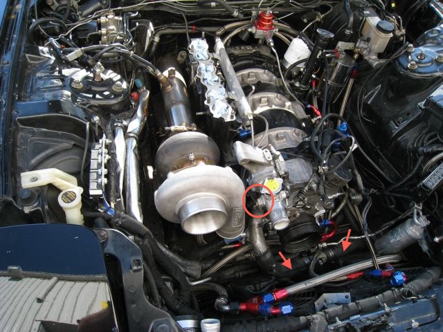
I have placed a circle around the sensor. It is less than one inch from the turbo. Thinking through this, how about if I move the sensor into one of the lower hoses that I have placed arrows on? Would this keep the sensor in a location that always has coolant flow? Or maybe something as simple as a heat shield? I could make one out of aluminum and bolt it to the back of the filler neck piping. I might try this first as it is easy and just might work. Built one about a month ago for one of my motor mounts and it is doing its job and holding up well.
 09-22-09, 09:30 AM
#3231
David,
What are you doing with the nipple on the top of the WP housing? Do you have it routed to the TB or just running a loop line to the rear plate? If you are not using it for anything, pull it out and tap it, install the sending unit there. This is where we have our Defi sensor and it works perfectly. Since it is located pre-thermostat it actually functions during warm up and gives a more accurate reading. Our fans are programmed to come on at 86C, the water temps on the gauge sit right at 182F on the gauge. I believe you still have A/C which will cause the temps to be a little higher.
I don't want to clutter up your thread with pics of our engine bay so here is a link:
http://www.banzai-racing.com/20B/20B_ebay_08-31-09.jpg
 09-22-09, 09:32 AM
#3232
David,
What are you doing with the nipple on the top of the WP housing? Do you have it routed to the TB or just running a loop line to the rear plate? If you are not using it for anything, pull it out and tap it, install the sending unit there. This is where we have our Defi sensor and it works perfectly. Since it is located pre-thermostat it actually functions during warm up and gives a more accurate reading. Our fans are programmed to come on at 86C, the water temps on the gauge sit right at 182F on the gauge. I believe you still have A/C which will cause the temps to be a little higher.
I don't want to clutter up your thread with pics of our engine bay so here is a link:
http://www.banzai-racing.com/20B/20B_ebay_08-31-09.jpg
What are you doing with the nipple on the top of the WP housing? Do you have it routed to the TB or just running a loop line to the rear plate? If you are not using it for anything, pull it out and tap it, install the sending unit there. This is where we have our Defi sensor and it works perfectly. Since it is located pre-thermostat it actually functions during warm up and gives a more accurate reading. Our fans are programmed to come on at 86C, the water temps on the gauge sit right at 182F on the gauge. I believe you still have A/C which will cause the temps to be a little higher.
I don't want to clutter up your thread with pics of our engine bay so here is a link:
http://www.banzai-racing.com/20B/20B_ebay_08-31-09.jpg
 09-22-09, 05:16 PM
#3236
When we eliminate the TB coolant lines, we also pull the nipple from the rear plate, tap & plug it. This eliminates the requirement for running a loop line, and gets rid of another failure point in the coolant system.
You are running a Microtech which should mean that you are using the factory thermosensor in the the location that bewtew is showing.
You are running a Microtech which should mean that you are using the factory thermosensor in the the location that bewtew is showing.
09-23-09, 01:17 AM
#3237
When we eliminate the TB coolant lines, we also pull the nipple from the rear plate, tap & plug it. This eliminates the requirement for running a loop line, and gets rid of another failure point in the coolant system.
You are running a Microtech which should mean that you are using the factory thermosensor in the the location that bewtew is showing.
You are running a Microtech which should mean that you are using the factory thermosensor in the the location that bewtew is showing.
09-23-09, 02:38 AM
#3238
Rotary Enthusiast
David start off with a heat sheild and see what happens. There will always be a temp diffrence pre and after the thermostat. I had mine in the thermostat housing, and it was always showing 3-4 degree more then the one on the other side of the thermostat. And i did not have radiant heat from a turbo. As my turbo was alot further back then yours.
So just try with a heat sheild and see what happens. That should lower the temps if that is the problem.
JT
So just try with a heat sheild and see what happens. That should lower the temps if that is the problem.
JT
09-23-09, 05:56 AM
#3239
He posted that earlier:
Our fans are programmed to come on at 86C, the water temps on the gauge sit right at 182F on the gauge. I believe you still have A/C which will cause the temps to be a little higher.
If I move the sensor to the lower radiator hoses as identified by the arrows in the pic, is it now behind the thermostat, meaning it will display temps during warmup? I'm pretty sure this is the case?
09-23-09, 09:13 AM
#3240
Rotary Enthusiast
He posted that earlier:
Our fans are programmed to come on at 86C, the water temps on the gauge sit right at 182F on the gauge. I believe you still have A/C which will cause the temps to be a little higher.
If I move the sensor to the lower radiator hoses as identified by the arrows in the pic, is it now behind the thermostat, meaning it will display temps during warmup? I'm pretty sure this is the case?
Our fans are programmed to come on at 86C, the water temps on the gauge sit right at 182F on the gauge. I believe you still have A/C which will cause the temps to be a little higher.
If I move the sensor to the lower radiator hoses as identified by the arrows in the pic, is it now behind the thermostat, meaning it will display temps during warmup? I'm pretty sure this is the case?
JT
09-23-09, 09:27 AM
#3242
 Those are the temps for his 3 rotor. Look at his post and click on the attached 3 rotor pic.
My radiator is a Pettit Racing one, supposed a "Nascar" used one. Who know if that is true but that was what I was told.
09-23-09, 09:29 AM
#3243
No u do not want to have the temp sensor there, as that's after the radiator. And that is the coldest place in the water system. And it will not see warm water at all untill after the radiator starts to get warm. And it will show alot of degrece lower then the other temp gauge instead of more.
JT
JT
09-23-09, 10:18 AM
#3244
"Our fans are programmed to come on at 86C, the water temps on the gauge sit right at 182F "
We use a custom mounted FD Koyo N-flow, with stock fans, functioning just like OEM (press the A/C button they kick on, etc)
David, install the sensor in the loop line you have running to the rear plate from the top of the WP housing, this will be the engine side of the theromostat and will allow the gauge to function properly during warm up. The only line I see with red arrows in your pic is the radiator hose.
Last edited by Banzai-Racing; 09-23-09 at 10:21 AM.
09-24-09, 02:52 AM
#3245
Rotary Enthusiast
never seen it done like that before, as stock it does not have that. where does that water come from, and where does it go to? and does it get blocked of once the thermostat opens? if not it will not cool the water going trough that line. and will go back into to your engine again.
but if that is so, you could put it there, but i would probably not use it. who set it up? cause i have never seen anything like that on a stock water system before.
BDW i run a griffin 3 row radiator, the biggest one i could fit in the front. But will go with a bigger one next year.
JT
09-24-09, 05:47 AM
#3246
hmmm the steel braided ones. i thought that was oil lines. hmmmm
never seen it done like that before, as stock it does not have that. where does that water come from, and where does it go to? and does it get blocked of once the thermostat opens? if not it will not cool the water going trough that line. and will go back into to your engine again.
but if that is so, you could put it there, but i would probably not use it. who set it up? cause i have never seen anything like that on a stock water system before.
BDW i run a griffin 3 row radiator, the biggest one i could fit in the front. But will go with a bigger one next year.
JT
I went ahead and bought the Microtech 'dongle" (still pissed at having to spend another $100 just to connect to my $1,500 ECU) and I'll hook up to the Microtech sometime this weekend. I'll then be able to compare the Microtech temps to the PLX temps to see if I have an issue with the temp. sensor location. If I do, then I'll move the sensor. If not and temps are still high, I'll go on to something else.
09-24-09, 07:53 AM
#3247
lol i'm sorry guys i was at the shop dealing with a zillion things and trying to read this all at once.
the reason why i was asking is because i dont think the koyo rad is efficient enough for the 3 rotor and i'm thinking about upgrading to a bigger radiator something custom made. i was actually going to have one made by a company that makes custom radiators for trucks and other vehicles.
the reason why i was asking is because i dont think the koyo rad is efficient enough for the 3 rotor and i'm thinking about upgrading to a bigger radiator something custom made. i was actually going to have one made by a company that makes custom radiators for trucks and other vehicles.
09-24-09, 01:42 PM
#3248
....the reason why i was asking is because i dont think the koyo rad is efficient enough for the 3 rotor and i'm thinking about upgrading to a bigger radiator something custom made. i was actually going to have one made by a company that makes custom radiators for trucks and other vehicles.
Allow me to enlighten: I previously ran some calculations to determine the cooling capacity of the Koyo, and what I determined is that the Koyo easily has the capacity to cool 531+ CONTINUOUS HP provided that there is [at least] 1760 cfm of airflow at an 80deg F ambient [or lower]. (1760 CFM is an equivalent air flow of about 10mph / 880fpm across the entire frontal area of the FD radiator)
Conclusion: This radiator is not/will not be the limiting factor for cooling in your setup; getting enough airflow through it is the most important thing. A larger radiator is nothing more than a heatsink unless you can get sufficient airflow through it to use the additional capacity. Note that larger/thicker radiator cores further reduce airflow, so there is a balance to be achieved for best efficiency.
09-24-09, 03:49 PM
#3249
Why don't you think the Koyo is efficient enough?
Allow me to enlighten: I previously ran some calculations to determine the cooling capacity of the Koyo, and what I determined is that the Koyo easily has the capacity to cool 531+ CONTINUOUS HP provided that there is [at least] 1760 cfm of airflow at an 80deg F ambient [or lower]. (1760 CFM is an equivalent air flow of about 10mph / 880fpm across the entire frontal area of the FD radiator)
Conclusion: This radiator is not/will not be the limiting factor for cooling in your setup; getting enough airflow through it is the most important thing. A larger radiator is nothing more than a heatsink unless you can get sufficient airflow through it to use the additional capacity. Note that larger/thicker radiator cores further reduce airflow, so there is a balance to be achieved for best efficiency.
Isn't it wonderful having an engineer on the forum that has designed thermo systems.
David is running a FMIC and an A/C condensor in front of the radiator thereby limiting the amount of air directly flowing through the radiator fins as well as the velocity of the air.
B/c of that ducting (air flow management really) becomes important to a reliable system. Take a look at some of the "ducting" that max cooper did on his car when he installed Pettit's big rad / FMIC combo. He had a thread in the Single Turbo section with pics. When I ran a Greddy FMIC, I actually cut out some of the top portion of the lip under the bumper opening so that I could get more direct air going under the IC to the radiator behind it. It was homemade and didn't look all that great (it was an experiment) but the result was noticeably better cooling.
One last thing. Alumrad.com is a great source for custom built radiators.
01-05-10, 08:41 AM
#3250
Here are some pictures and video from David's dyno session on 12/29/2009. The car made 555whp and 476 torque peaking somewhere between 5500 and 5700rpm. David has the graph. The boost was not stable, fluctuating between 12 and 14 pounds, because of a waste gate spring that was too soft. Everything was shot with a Canon PowerShot SD1200 IS point and shoot camera.
I did not shoot any pictures with the head lights up/of the front end, as David is still working on his HID conversion, as can be seen in his Sleep Eyes thread that's currently going in the 3rd gen section. I did not want to spoil the surprise of what he's working with.
Thanks again to David for letting me come and hang out.


There are more dyno videos that can be found in my photobucket in the link below. Enjoy.
http://s265.photobucket.com/albums/i...s%203%20Rotor/
I did not shoot any pictures with the head lights up/of the front end, as David is still working on his HID conversion, as can be seen in his Sleep Eyes thread that's currently going in the 3rd gen section. I did not want to spoil the surprise of what he's working with.
Thanks again to David for letting me come and hang out.
There are more dyno videos that can be found in my photobucket in the link below. Enjoy.
http://s265.photobucket.com/albums/i...s%203%20Rotor/