When you click on links to various merchants on this site and make a purchase, this can result in this site earning a commission. Affiliate programs and affiliations include, but are not limited to, the eBay Partner Network.
Hello guys, I have a 1990 N/A rx7 that is in the process of being put back together. The previous owner seems that he did not know what he was doing and started chopping wires left and right. The engine harness is basically dead and I got a replacement for it but am having trouble finding a front/body harness. So I think I have to work with what I have. That being said the harness that was left behind has also been mangled and chopped up too. I really do not know what I am doing. I have uploaded pictures of some of the chopped up parts of the harness. First, I would like to clean up the battery cables and terminals. How would I go about doing this? I mean what kind of cable would I use for the negative side? What kind of cable would I need to buy for the positive side? The positive side seems to have two wires is that normal. Also, the negative side of the battery cable seems to have a ground coming out of it? I also found a chopped up cable along the harness any ideas on what it could be? If you have any suggestions don't hesitate to leave a comment or PM me. If you need more or better pictures don't hesitate to ask. I am truly at a loss when it comes to wiring. I'll continue to go through the harness I am sure that I'll find more problems. Thank you in advance.
It looks like you have a very time consuming project on your hands! I recommend using the Wiring Diagram Manual (WDM) as your guide. It has physical locations of connectors however, the size of the drawings will make it difficult to identify specific locations. It does help identify ground locations and such. As for the battery cables, search the forum for the best possible replacement options. I don't think the original battery wires are available. The next best thing would be to check out a West Marine store (or similar) for marine grade battery cables. The gauge of wire you may need would either be 4 or 8 gauge. I would definitely replace those nasty battery terminals to ensure the new battery is properly connected. Use terminal washers (red & green or red & black) to keep extra crud from forming on the terminals. For specific connector issues, you may want to highlight specific connectors and ask to help ID them. In your 1st picture, that wire hanging from the transmission bell is a ground.
It looks like you have a very time consuming project on your hands! I recommend using the Wiring Diagram Manual (WDM) as your guide. It has physical locations of connectors however, the size of the drawings will make it difficult to identify specific locations. It does help identify ground locations and such. As for the battery cables, search the forum for the best possible replacement options. I don't think the original battery wires are available. The next best thing would be to check out a West Marine store (or similar) for marine grade battery cables. The gauge of wire you may need would either be 4 or 8 gauge. I would definitely replace those nasty battery terminals to ensure the new battery is properly connected. Use terminal washers (red & green or red & black) to keep extra crud from forming on the terminals. For specific connector issues, you may want to highlight specific connectors and ask to help ID them. In your 1st picture, that wire hanging from the transmission bell is a ground.
Ah ok thank you for the resources my engine is coming in next week. I'll post more pictures if I need help identifying wires. Again thanks for the resources.
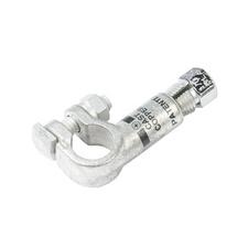
This is a compression battery terminal, these work as a great alternative, I can not stand those bolt clamp style terminal, and would defiantly be working on replacing the positive and negative battery cables at lease. It may take some creativity and universal cables to make it work but well worth it. I have used these and have no problems.
Okay, I'm going to stop the misinformation right here and now.
Battery Terminals: There is no way a single grub screw can carry enough current to power our cars. It's a matter of surface area. Marine Battery Terminals are the way to go. Aaron Cake demonstrated this years ago, I did the same and it has proven reliable at every turn on multiple vehicles. You can find them at any parts store or even Walmart.
It is highly recommended to replace your starter/battery cables. You can use regular 4awg battery cable from the parts store, or go with welding cable as I do. The overall method is detailed here: Proper RX-7 Grounding Procedures. I made this video for the Ford Escort Owners Association to demonstrate how to solder lugs onto cable properly:
. These went into her car and it corrected the well-known ground problems plaguing 97+ Escorts. Same stuff I did to my RX-7 and Expedition daily driver years ago.
Battery to chassis ground is 24", chassis ground to starter ground is 24" Battery positive to starter is 48". Some red/green heat shrink on the lugs (over top of the double wall adhesive lined heat shrink) is a good idea to differentiate the cables from each other. Given how a previous owner was 'fixing' it, it's probably a good idea to disassemble the front harness to extract the alternator/fuse box cable. Clip the staple off, give the fuse box cable a ring terminal (toss the old Alt cable) and run fresh 4awg cable (~30" give or take, measure first though) to the alternator. Both attach to the positive battery terminal. Your car will thank you with brighter lights.
As for the other electrical issues, the S5 wiring diagrams are your best friend.
I appreciate your zeal in providing some information regarding battery terminals, battery cables, videos, and web links. I agree with some of your recommendations while I disagree with some of your opinions.
I agree with:
1. Replacing the battery cables is recommended, especially when the engine is out of the bay.
2. Recommendations on wire size (gauge) and lengths.
3. Demonstration videos for soldering wire into a terminal.
4. Using the WDM (Wiring Diagram Manual) as reference material.
5. Provided a link to Aaron Cake's Proper Grounding procedures.
6. Marine grade wire & connectors would provide the greatest longevity of the repair.
I disagree with:
1. Your attention statement of "...stop the misinformation right...now". If something was factually wrong within this thread then support your argument with facts. Do not just say that something is wrong about battery terminals then express what should be done. If a procedure worked for you then share those lessons. However, the moment you tell someone to do something "your way" then they often will not listen.
2. Using marine grade connectors, battery terminals, or heat shrink are not the only options available. They may be the best option but not the only option. What's wrong with a compression fitting on a battery terminal?
I reiterate that I applaud the fire brought to this thread. You have a lot of good recommendations and observations! However, I believe the audience (me included) was switched off from your content because of its delivery. I doubt that was intentional. We are unaware of the OP's skill set, budget, or time constraints. Therefore, we provide enough information for the OP to make an informed decision. Would you agree?
Gen2n3, I agree that reasonable skepticism is a healthy thing. And as you may be aware of, some don't have the best understanding of proper electrical reasoning. When I got my RX-7 back in 2007, I certainly didn't but I had the drive to learn. Icemark and Aaron Cake showed me quite a bit, along with reading the 2nd Gen FAQ. After reading Aaron Cake's entire Project Tina conversion, the basis for my opinion on how to make reliable connections took shape. Here is it explained: https://www.aaroncake.net/rx-7/proje...oct12005-2.htm
"The power block is something that I made using a block of plastic, two M8 bolts and a little bit of 3MM sheet steel. This was done because I was totally unhappy with the distribution blocks that are available commercially. Most are designed for stereo installations, and while they look nice, their electrical quality is a little questionable (sorry, but one grub screw that you tighten into a 4 AWG wire does not provide enough contact to move 300-400A) and the brittle plastic used tends to crack (at least in my experience). This block is very strong, and since the cables connect with proper lugs, electrically very good as well."
On further research, I was mistaken in understanding how Compression Battery Terminals work. Based on this link from Amazon (
), the male threaded portion is slipped over bare cable, then screwed into the terminal. It appears that the threaded portion is intended to create a pressure weld connection with the cable, based on the torque applied when mating the two terminal sections together. I believe the reasoning in this case is akin to crimping a terminal onto a cable. For cables of this size, a hydraulic crimper would be required to produce a useable cable. If one can produce force akin to such a device using normal tools associated with these terminals, I would be more than happy to observe and correct my opinion to reflect the results.
), I'll try to be as respectful as possible. I had 5 cables done by a welding supply shop with a crimper like this. Of the 10 lugs, 8 failed before install on my 97 Expedition. I discovered this when my 12lb Maine Coone swatted one cable and then ran after the detatched lug. Suffice to say that it got me suspicious about the rest. Tested them with regular hand force, 7 more failed with little effort and I wasn't so sure about the last two. Got the torch out and soldered them all, just like ObliqueFD and I did on Project OldTree in 2012.
Ampacity of a connection is based on the cross-section of the connection. More area = more current able to be delivered. However, if the connection is not electrically sound (corroded, poor crimp, etc), the biggest cables won't benefit you.
Pride aside, attempting to be cheap with a RX-7 just pisses off the omnipotent god Murphy, who then sends rust demons to kick you right in the nuts and empty your wallet. Speaking from experience as a frugal FC owner, I once attempted to use an autozone exhaust patch kit on one of the original mufflers to close up a crack temporarily and ended up spending $700 4 days later on a new catback from Racing Beat. Car was unhappy with this attempt to be cheap, so it backfired and tore it off. Learn from my mistake.
Marine battery terminals have the fewest possibilities for failure as they are one piece with a stud cast into the terminal. Plus, their wing nuts means needing zero tools to disconnect/reconnect the battery. And they're dirt cheap too, $4 at Walmart. As for using double-wall adhesive lined heat shrink, I'm going to defer to Aaron Cake as he is FAR more capable of a scientific explanation than I am. I just do so because I hate doing the same job twice when is is preventable by spending $1 more at Harbor Freight (https://www.harborfreight.com/42-pie...ing-67598.html).
This what I used, I stripped about 3/4 inch of wire, packed the other end full of solder and tightened the nut. I have a 200 watt amp with 2 10 inch subs with no prblems at all.
Thanks for sharing the pic. The yellow stripe gives the illusion that the terminal is considerably larger than the wire. Glad that option is working for you!
Akagis,
Thank you for sharing more of your experience and research! I also learned a few things from it. I believe this thread will not only help the OP but also help other members who wish to tackle this project in the future. I'd like to confirm the replacement parts you recommend, they are:
1. Positive and Negative Marine grade battery terminals, solder type.
2. Marine grade cable, 4-AWG for positive and negative cables.
3. Length of cable varies upon function:
3.a. Battery Negative to Chassis Ground = 24"
3.b. Chassis Ground to Starter Ground = 24"
3.c. Battery Positive to Starter Positive = 48"
3.d. Battery Positive to Alternator Positive @ Connectors A-04 and A-05 = 30" per connector (verify length 1st though)
3.e. What length is needed for Alternator Negative to Chassis Ground? Is the same 4-AWG wire recommended? I don't think that was discussed.
4. Marine grade double walled heat shrink to protect any exposed wire at each wire end.
5. Red & Green heat shrink to identify Positive and Negative wires. Red for Positive and Green for Negative.
6. Red & Green or Red & Black battery terminal anti-corrosion washers*
7. Battery terminal protector (spray)*
* - These are my suggestions to help reduce corrosion build-up on battery terminals. The washers help to absorb gases/acid that escape a battery and the terminal protector spray creates a barrier between each terminal and the air.
JC14,
Does this give you a clear picture for battery cable replacements?
The cable terminals to be soldered on are called Lugs and look like this: https://www.grainger.com/product/23Y...180530155125:s
Those are for 2awg, but you get the idea. You can find them for ~$3 per pair at Walmart, Harbor Freight or any parts store. A welding supply store will also have them and possibly for less. The 'ring' on it hooks onto the stud on the Marine Battery Terminal and gets tightened down with the wing nut.
I don't have an exact size for heat shrink, but the stuff I previously referred to has the correct size in it. "If it fits, I sits" works fine here.
4awg cable, either regular car battery cable or welding cable works. Nothing fancy needed here. I pay about $1-1.50 per foot on average. Cut with diagonals, strip with a pair of common scissors. You'll have to 'feel' how deep to cut with the scissors, just be careful and take it slow and it'll work fine.
Red/Green heat shrink is optional. I just use red/green electrical tape and some Raychem (from TE Connectivity) clear heat shrink leftover from doing the 20B engine harness. Mouser Electronics has it, but you may be able to find it locally too.
3d: Alternator output stud to Battery Positive. Chances are that upgrading your alternator is on the horizon, as a regular stereo can easily overtax the stock 70/80A ones, so running some 4awg cable here is a wise idea (measure the length with some string). A 100A FD alternator (with the correct adapter pulley from Mazdatrix) is a plug & play swap for your S5. My personal preference is a 130A Ford Taurus alternator (92-95 Taurus/Sable/Windstar with 3.8L V6). But with any alternator upgrade, you'll have to upgrade the fuse it runs through (aka Main Fuse). 120A for FD alt, 140A+ for Taurus Alt respectively. My 20B has it running through a 140A fuse (Honda Accord style) sourced from a 99 Dodge Ram. Expedition (same 130A output) has a 175A mega fuse from the factory. Either works fine.
3e: There is no ground cable for Alternator to Chassis/Battery negative. It is grounded through its mounting bolts to the engine, which travels up the starter ground cable. Most cars are like this, including my Expedition. As long as your main ground cable connections are good, all is good here.
Adding some Dielectric grease where cable meets lug (after it is soldered, before adding heat shrink) to cover the gap between the cable and lug's 'cup' is good practice to prevent ANY moisture from reaching the bare cable inside. I use "Super Lube" from Harbor Freight, but there are other options out there too. If you find a cheaper alternative, please let us know.
Are you speaking from experience with Palm Tree's wire harness rebuild?
They rebuilt my FD's motor and provided exceptional service! The owner is a real down to earth guy and is very meticulous! For those in and around the Central Valley - from Sacramento to Bakersfield, Victorville to the Bay area, Morro Bay to Bishop, then consider Palm Tree your rotary life-line!
Thanks for sharing the pic. The yellow stripe gives the illusion that the terminal is considerably larger than the wire. Glad that option is working for you!
Akagis,
Thank you for sharing more of your experience and research! I also learned a few things from it. I believe this thread will not only help the OP but also help other members who wish to tackle this project in the future. I'd like to confirm the replacement parts you recommend, they are:
1. Positive and Negative Marine grade battery terminals, solder type.
2. Marine grade cable, 4-AWG for positive and negative cables.
3. Length of cable varies upon function:
3.a. Battery Negative to Chassis Ground = 24"
3.b. Chassis Ground to Starter Ground = 24"
3.c. Battery Positive to Starter Positive = 48"
3.d. Battery Positive to Alternator Positive @ Connectors A-04 and A-05 = 30" per connector (verify length 1st though)
3.e. What length is needed for Alternator Negative to Chassis Ground? Is the same 4-AWG wire recommended? I don't think that was discussed.
4. Marine grade double walled heat shrink to protect any exposed wire at each wire end.
5. Red & Green heat shrink to identify Positive and Negative wires. Red for Positive and Green for Negative.
6. Red & Green or Red & Black battery terminal anti-corrosion washers*
7. Battery terminal protector (spray)*
* - These are my suggestions to help reduce corrosion build-up on battery terminals. The washers help to absorb gases/acid that escape a battery and the terminal protector spray creates a barrier between each terminal and the air.
JC14,
Does this give you a clear picture for battery cable replacements?
Cheers,
George
Yup all the info being shared is helping a lot. I already ordered some supplies to make a new positive cable(s) and I think I have that part figured out. Now the only thing to do now is to go through the harness and see if there are any more problems
Okay, I'm going to stop the misinformation right here and now.
Battery Terminals: There is no way a single grub screw can carry enough current to power our cars. It's a matter of surface area. Marine Battery Terminals are the way to go. Aaron Cake demonstrated this years ago, I did the same and it has proven reliable at every turn on multiple vehicles. You can find them at any parts store or even Walmart.
It is highly recommended to replace your starter/battery cables. You can use regular 4awg battery cable from the parts store, or go with welding cable as I do. The overall method is detailed here: Proper RX-7 Grounding Procedures. I made this video for the Ford Escort Owners Association to demonstrate how to solder lugs onto cable properly: https://www.youtube.com/watch?v=-Jr8_04BajQ.
It's not too difficult, my fiancee got it on her first try too here: https://www.youtube.com/watch?v=sG6y0VjqR2k. These went into her car and it corrected the well-known ground problems plaguing 97+ Escorts. Same stuff I did to my RX-7 and Expedition daily driver years ago.
Battery to chassis ground is 24", chassis ground to starter ground is 24" Battery positive to starter is 48". Some red/green heat shrink on the lugs (over top of the double wall adhesive lined heat shrink) is a good idea to differentiate the cables from each other. Given how a previous owner was 'fixing' it, it's probably a good idea to disassemble the front harness to extract the alternator/fuse box cable. Clip the staple off, give the fuse box cable a ring terminal (toss the old Alt cable) and run fresh 4awg cable (~30" give or take, measure first though) to the alternator. Both attach to the positive battery terminal. Your car will thank you with brighter lights.
As for the other electrical issues, the S5 wiring diagrams are your best friend.
Thanks for the info. Instead of just trying to save the battery cables I think I'll just make new ones. I just purchased some supplies to create new battery cables battery cables. On to something a little different you guys would not happen to know if the s5 coupe and s5 vert ECUs are the same? I am in need of an s5 N/A ECU and I found someone with a manual vert close by that is willing to sell his to me.
Are you speaking from experience with Palm Tree's wire harness rebuild?
Yes, they rebuilt the harness for my 88 turbo and I've not had any issues since! Great guys.
Originally Posted by JC14
That sounds great do you know a ballpark on how much they charge?
It's $400 with $100 refund if you give them an exchange harness (they had one in stock when I ordered) so they rebuilt me a harness for $400 and then refunded me $100 when I sent my old one back.