When you click on links to various merchants on this site and make a purchase, this can result in this site earning a commission. Affiliate programs and affiliations include, but are not limited to, the eBay Partner Network.
After starting my Rx7 for the first time in almost two years, I was surprised by how poorly it ran. I can�t recall if it ran this badly when I parked it, or if it has deteriorated. Either way, something had to be done. I have good compression, good spark, good timing, and good fuel delivery. All of my electronics seem fine. This leaves the likely culprits as vacuum leaks and malfunctioning emissions equipment. So I decided to rebuild the entire intake tract to deal with all possible issues at once. I figured a write-up would be in order, since I didn�t find anything that covered the entire system. I�m going to try and be as comprehensive as possible, but I also recommend reading the Factory Service Manual to ensure you have a backup reference. This is for an S4 NA, so S5 and TII intakes are different. You can use this guide as general advice for those engines, but the manifolds and hose locations are different, so the details will differ.
What this covers: Replace gaskets for entire intake tract. Test various components, and replace perishable parts.
What this does not cover: Emissions deletion. You can use this guide to access the emissions components, but I�m retaining mine.
Required tools & supplies:
Wrenches (10mm, 12mm, 14mm, channel-lock)
Sockets (10mm, 12mm, 14mm) and miscellaneous extensions)
Screwdrivers (flat-head, Philips)
Shop rags, carb cleaner, brushes.
Gaskets
Recommended:
Air compressor with wand attachment
Box-cutter blades
RTV (I use grey for this application, and have always had good results)
Crush washers for the OMP injectors, miscellaneous o-rings for the injectors, vacuum hose, coolant hose, fuel hose.
Notes:
Label every single vacuum hose as you go. Skipping this step is not worth the guessing game later as you try to reassemble it. I�ll provide a vacuum diagram I found, but it�s easier to not risk it.
When you have a section of the intake open, especially if you are walking away or taking a break, block it with a shop rag. That way you don�t let dirt, dust, or small animals sneak into the engine.
Wear gloves, and if/when using chemicals make sure to do so in a well-ventilated area. Wearing a mask is recommended as well. Take the time to read the back of the can and make sure you�re wearing appropriate PPE.
You will lose some coolant during this project, so if you�re nearing the change interval it is a convenient time to replace it. Otherwise, just make sure to top it up and burp the system on startup.
You will lose some fuel during this project. Use caution, as fuel is very flammable, and has a strong odor.
At all times when working on a vehicle, you should disconnect your negative battery terminal and tuck it aside.
Step 1: Disconnect your intake tube. One end connects to the mouth of the throttle body, the other connects to the MAF at the front near the air box. The big tube is held on using a large clamp, loosened using a bolt with an inset Philips head. The little tube is held on with a hose clamp. You can choose whether to disconnect the upper or lower hose clamp, it makes no difference. The elbow into the throttle body connects with two acorn nuts, keep these safe. They can be replaced with regular nuts, but the acorn nuts look nice.
Step 2: Disconnect the OMP rod on the throttle body, at the primary throttle blade linkage. Zip-tie it to a convenient space so it doesn�t fall down.
If yours has the stock split pin, save it if possible. Mine was long gone, and every time I remove this rod I replace the pin with a piece of bent paperclip. Make sure to bend it so it stays tight, and it doesn�t get caught on anything when the linkage moves through it�s full range.
Step 3: Whether you drain your coolant is up to you, but if you don�t you�re going to lose some at this step. I�d say don�t bother draining it unless you�re nearing the time to change it anyways.
Remove the two hose clamps on the thermo-wax near the throttle body. Drain them into an empty water bottle if possible, and then set aside for re-use if it�s still good. Zip tie them somewhere in the engine bay out of the way for now. Disconnect the rear vacuum hose at the plastic cylinder (I think it�s called a thermovalve). The front hose goes to the actuator for the double throttle blades, so you can leave it on (I deleted mine because it was leaking vacuum).
Step 4: Remove the throttle cable. You can do this by pushing down on the linkage at the front of the throttle body, where the OMP rod connects. At the same time as you�re holding the linkage open, reach behind the throttle body and unhook the cable from the other side of the same linkage (not pictured). It�s tricky the first time because you can�t see it, but after that it becomes easier. Once these are all removed, the throttle body comes off after removing 4 12mm nuts.
The metal tube running along the back of the Dynamic Chamber can be removed with 1-2 10mm bolts. Keep all of the rubber air tubes on the driver�s side connected for now; they don�t need to be taken apart.
Removing the BAC is easy. Disconnect the plug. There are two 10mm bolts. There�s also a water passage here that loops through the BAC to the back of the throttle body. You can remove it without taking off the hose clamps by using an impact style Philips head screwdriver to loosen the screws that hold it to the BAC valve. You won�t lose any water from this joint that way. However, if you�re replacing your water hoses it�s advisable to leave this connected and just take the hoses off.
There are two 10mm bolts hiding behind that rubber tube that hold the throttle cable bracket onto the Dynamic Chamber. Two 10mm bolts hold the big air solenoid (don�t know its real name) on, and there�s a hose clamp connecting it to the dynamic chamber. There�s also a vacuum hose and a connector for the Intake Air Temperature sensor. Lastly, there�s a 12mm bolt holding the Dynamic Chamber to a bracket, this also needs to be removed. There�s a similar bolt on the front of the Chamber, which can be reached most easily with a wrench as it�s behind the alternator
Step 5: Remove the secondary fuel rail by loosening the two bolts on top of the UIM, then the clamps on either side that hold the fuel hoses on. You will lose some fuel here, so first make sure to have rags ready. As always, make sure there are no ignition sources nearby and you are wearing goggles. If you are working inside a garage, open the door to get some fresh air. Once the hoses and bolts are removed, lift the rail off and the injectors will likely come with it. Put them in a Ziploc bag and place them in a safe place.
You will also have to disconnect several vacuum lines. Make sure to label where each of them goes, or reassembly will be much more difficult.
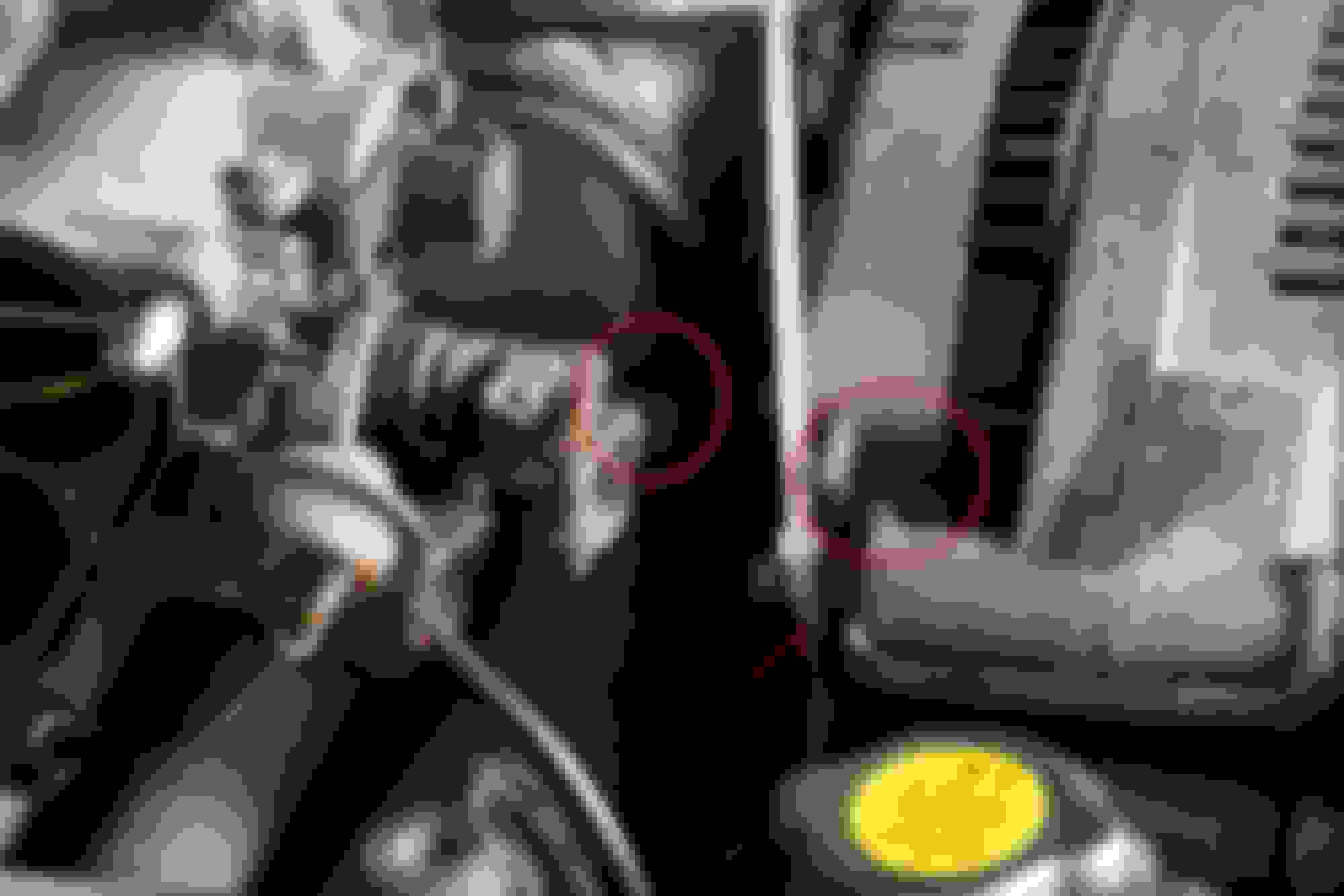
The red blocked line on my manifold is for the sub-zero cold-start assist. I�ve removed the system, as it does nothing except introduce a possible vacuum leak
Pictured below are the plastic injector diffusers. They are designed to help atomize fuel better. If at all possible, DO NOT REMOVE THEM. They are very fragile, and don�t like frequent removal. If you absolutely want to take them out, the only safe way is to wait until the manifold is removed. They also have sealing o-rings, which definitely need to be replaced if removed. Whether you want to replace the o-ring is up to you; I have replaced all of mine. But be prepared to pay for a new set of diffusers as they often fall apart.
Step 6: Remove the UIM by removing the 4 12mm nuts and 12mm bolt on the flange that hold it to the LIM. Once they�re off, it should just separate. If they have been RTV�d together in the past, it may be stubborn. What I did is gently use a razor to separate RTV on one corner, then once that corner began to lift the rest of the gasket separated.
(Here the ACV is removed, but we'll take that off in a later step)
Step 7: The EGR valve is held on with two bolts. You can examine to make sure it works by applying vacuum on the vacuum nipple and seeing that it holds vacuum. If it doesn�t the diaphragm has broken and the valve needs to be replaced. You can also clean the carbon out of the bottom, provided the valve still works.
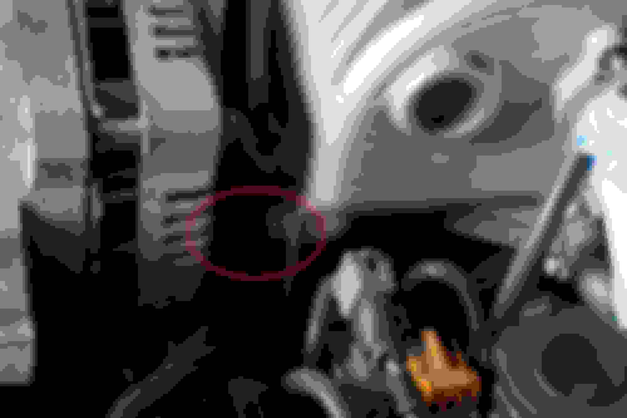
Step 8: Disconnect your O2 sensor cable to keep it out of the way. The ACV can be removed by taking out the nut and two bolts, there is one up top, and then one on either side of the bottom. There is also an air hose at the front of the ACV (to the air pump) and on the side (to the silencer in the passenger side wheel well). Make sure to remove the small diaphragm that goes in the round hole (hole is pictured, diaphragm is not).
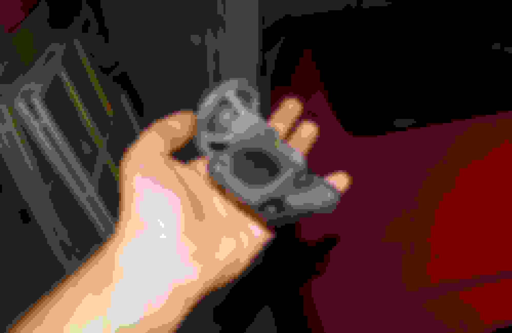
You can then turn your attention to the port actuators. They are held on by two 10mm bolts, and the top linkage slides off the small post once the bolts are removed. The one at the front is a bit tricky to reach with the air pump in place, but using an extension it can be done.
Last, disconnect the two OMP injectors on the engine side of the LIM (14mm open ended wrench), and the air hoses at the back of the LIM. The small hose for the exhaust pressure to the actuators needs to be disconnected as well. Vacuum hoses connect to the injectors, so those will have to come off as well. There are also a few vacuum nipples on the LIM, as always remove and label the hoses.
Step 9: Remove the 4 12mm bolts and 2 12mm nuts holding the LIM on. After those come off, remove the LIM and put it aside.
Make sure to put rags in the intake ports to block them off. You can take out the port sleeves in the top ports, but I ended up finding mine were missing! I always thought the boost I felt at 4000 rpm was the ports opening, I guess I was just feeling the lack of power below that.
Anyways, this is the point at which you can reach anything you need to replace on top of the engine. Though I had already done it so skipped it this time, you can (and should, depending on condition):
Replace all vacuum hoses, ideally with silicone lines.
Replace the fuel hoses (use only hose rated for injection systems, and replace the clamps too)
Replace the coolant hoses
Have the injectors serviced. Note that there are two of those fragile diffusers under the primary injectors too. I recommend not touching them if possible. It�s easy for them to break.
Replace OMP injector crush washers.
Clean your throttle body and BAC valve if necessary
Test the solenoids on the vacuum spider (apply 12V to the spade terminals and listen for a click).
Replace or delete the Fuel Pulsation Damper on the Primary Fuel Rail.
Obviously some of this will depend on the condition of your specific vehicle, so I can�t advise on whether you should do it. What I will say is that spending a bit of money now on new hoses is cheaper than spending the same money later + paying for new gaskets and doing this job twice.
You can also perform an emissions delete on your vehicle, which will of course require the appropriate block off plate set. I retained mine. Make sure to check local laws and ensure you�re in compliance.
Step 10: Clean all of the flanges where the gaskets go on your manifolds. In my case, I used RTV last time so it is somewhat springy. I find the best thing to do is plug the intake to prevent debris falling in. Then you can (carefully) use a razor blade to scrape as parallel as possible to the surface. If done carefully, it will become squeaky clean and shiny. After that, wipe with carb cleaner until the cloth comes away clean.
Left side of the photo has been cleaned, right side is still dirty
A word on RTV: You don�t actually have to use RTV, since gaskets are available for the flanges. I only use it as a gasket dressing on areas where the mating surface is scratched. Some of these were cleaned roughly by the previous owner (or whoever he paid to work on the vehicle), which left some gouges in the surface of the aluminum. An example is pictured below. Now, grey RTV works for me, but Permatex doesn�t recommend it as a gasket dressing. What you use is up to you depending on what you have and what is specified by the manufacturer, but grey Permatex is what I have used with good results. You also only want to use a skim coating, as it is only filling small imperfections and not creating a gasket. Using too much can cause it to ooze into the passages, which is no good. I also never use RTV on the engine side of the LIM gasket. RTV is frustrating to remove, and removing it from the surface of the intake ports on the engine would be irritating and present the risk of dropping debris into the engine. Under no circumstances do I recommend that.
Accordingly, where / when you use RTV or gasket dressing is up to you. Ideally, it should not be necessary at all.
Some of the runners also have brown carbon gunk inside, you can remove this with carb cleaner and a toothbrush.
Once all of the flanges have been cleaned as well as they possibly can, wipe them down with carb cleaner until the rag comes away clean. If you have access to a compressor with wand attachment, use it to blow anything out of the runners and passages. Don�t forget to clean the engine where the LIM mounts, but don�t use the compressor to blow into the intake ports. We are taking gunk out, not shoving it in.
Reassembly: This is where reassembly begins. I recommend taking out the port sleeves and cleaning them.
Then you can use carb cleaner and a rag on your finger to gently clean the aux ports on the engine. After the sleeves are cleaned, lubricate them with some sort of oil. Slide them back into their ports, making sure to make it so the opening of the sleeve faces the inside port. The rear sleeve should have the opening face towards the front of the car, the front sleeve should have the opening facing the rear of the car. This sets them in the �open� position.
Then, take your LIM and turn the shafts for the actuators to match the �open� position of the sleeves. If looking at the outside of the shaft where the actuator connects, this position is with the rod rotated as close to the actuator as possible.
Assembly: I�m not going to explicitly mention it any further, but ensure that you remove all of the rags that you have been using to block the ports. Always err on the side of caution and check that the ports are clear while reassembling. I also didn't take pictures of reassembly, as it is reverse of removal.
Place your LIM > block gasket onto the engine, and then install the LIM ensuring the notches in the shafts engage on the auxiliary sleeves. Install the nuts on the LIM first, then the bolts afterwards. Tighten in an across pattern, to 14-19 ft-lbs. This is (to my knowledge) the torque spec for the entire intake tract.
After the manifold is installed, turn the actuator rods with your fingers. It should turn freely, and you should hear the sound of the sleeves turning in the engine.
Reinstall the OMP injectors. You can re-use the crush washers, but I recommend replacing them. It is an irritating part to have to service later. Reconnect the vacuum hoses to the injectors, plus the one between them on the LIM.
The port actuators can be tested by blocking one of the ports with your finger, pushing a vacuum hose against the other port, and blowing into the hose. You should see the rod retract into the actuator as you blow into it. If not, you�ll need to replace the actuator.
The actuators can then be reinstalled onto the LIM with the new gaskets. Hook the linkage into the rod on the auxiliary port shaft, then bolt it down.
The ACV can now be reinstalled. First, put that diaphragm we removed earlier back into the round port on the LIM. Then place the ACV into location and bolt it down. Don�t forget to reconnect the hoses and electrical connectors.
The EGR valve reinstalls with two bolts. It connects with one vacuum hose to the vacuum spider.
Now, this is the point where the UIM goes back on. Once you install it, you won�t be able to reach the EGR, Primary Fuel Rail, OMP injectors, fuel hoses .etc. Make sure you�ve done all you need to do under here before proceeding. Reinstall the UIM with the four 12mm nuts and one 12mm bolt, torqueing 14-19 ft-lbs in an across pattern just as before.
Reconnect your vacuum lines on the UIM. If you labelled them as recommended, this should be a relatively simple task. If not, refer to the vacuum diagram provided.
(This is an S4 NA diagram, make sure to use the appropriate diagram for your vehicle. Credit for this one goes to felixwankel88 in this thread.)
Install the BAC with gasket, making sure to tighten the hose clamps on the rubber air hose that connects to it. Install the brackets for the big air solenoid, the throttle cable, and the bolts that hold on the tube that runs along the back of the Dynamic Chamber. Reconnect the electrical connectors. Don�t forget the double spade connector for the Intake Air Temperature sensor.
Reinstall your Secondary Injectors and fuel rail. The injectors go in first, using motor oil to lubricate the top and bottom rubber seals. Then gently install the rail on top, it should slip on without too much difficulty. Finger tighten the bolts, then install the front and rear fuel hoses. Last, tighten down the bolts.
The throttle body goes back on, making sure the rubber spacer is facing the right way (compare the air passages on the spacer to the manifold, you�ll see they only line up one way). Install the throttle cable by pushing down on the linkage and slipping the cable back on with your other hand. Reconnect the OMP rod to the linkage, and plug in your TPS.
Now that this is back on, all you have to do is ensure that you have connected all the vacuum lines, reconnect the intake tube to the MAF and you should be ready to go.
If anyone thinks of something I�ve forgotten, please comment so that this write-up is a more complete resource
Idle is 800 rpm or so, first rev is 3000 rpm, second is 5500 rpm or so. The smoke is from the hefty amount of premix I put in there (since this is the first start in two years).
Great post, I hope to rebuild my intake in preparation to do a turbo setup with this soon!
Thank you too Hopefully this post is of some use to you. When I got my Rx-7 it was my first car, so I knew nothing at all about how to do maintenance or repair. The forum has been (and continues to be) the single most valuable and useful resource for me. Whenever possible, I like trying to give back some of the help I received.
Make sure to create a build thread for your turbo setup!
This is a good writeup. We can sticky this if you guys would like.
Thank you I'd be happy if it was stickied. A lot of new users have issues with idle or performance that boil down to a vacuum leak, stuck actuators, poor injectors, or malfunctioning emissions equipment / solenoids. Hopefully this will help some of them diagnose and repair their issues.
One oversight in my initial write-up was that I missed two seals; the ones that seal the actuator shafts for the port sleeves. I've never actually replaced them, but since everything is apart again this is a good opportunity:
The two philips-head screws are the only thing holding the shaft in. Be forewarned, they do not want to come out. Three of mine required lots of heat, oil, and an impact driver. The last one was hopeless, so I ground it flat and took the shank out with vise-grips. Also, pay attention to the orientation of the linkage at the end of the shaft; Keep in mind that in this photo the manifold is upside down on my table. If you forget or the photo doesn't make it clear, just compare it to your actuator when installed and you'll see which way the linkage should fit. The other side is mirrored.
This is the other side (rear). Once you have the shaft out, you can find the offending seal. It's pretty crusty after 33 years.
This is how the shaft goes together for reassembly: The outer piece with the screw holes slides onto the end of the shaft. Orient it so the linkage rotates between the two stops, with the linkage on the side that allows more rotation (ie. in this image, the linkage would go between the stops on the side facing away from the camera). The notched disc engages on the shaft in the small channel directly above it in the photo. Lastly, the washer goes on between the notched disc and the seal itself.
If anyone knows of an alternate source, compatible seal from another application, or DIY solution, please let me know. Otherwise my next project will be making a mold and casting one out of urethane.
EDIT: Come to think of it, based on the way it's assembled, a skim of RTV on the bottom of the top piece with the screw holes should seal just as well against the flange. Unless there's something I'm missing, that would negate the need for the seal.
Last edited by WondrousBread; Jun 18, 2020 at 08:29 PM.
@WondrousBread hey bread, i was reading through this guide (which is fantastic btw) but what is the vacuum spider in this context?
"Test the solenoids on the vacuum spider (apply 12V to the spade terminals and listen for a click)."
Hi Maaaaackle
The vacuum spider is sometimes called the solenoid rack. It's the steel bracket that has solenoids mounted on it and has all of these steel tubes. If you look at the vacuum tube diagram I posted, the solenoids are depicted on the bottom right.
If I could do this guide again, I would take a few more pictures as I went along
One oversight in my initial write-up was that I missed two seals; the ones that seal the actuator shafts for the port sleeves. I've never actually replaced them, but since everything is apart again this is a good opportunity:
The two philips-head screws are the only thing holding the shaft in. Be forewarned, they do not want to come out. Three of mine required lots of heat, oil, and an impact driver. The last one was hopeless, so I ground it flat and took the shank out with vise-grips. Also, pay attention to the orientation of the linkage at the end of the shaft; Keep in mind that in this photo the manifold is upside down on my table. If you forget or the photo doesn't make it clear, just compare it to your actuator when installed and you'll see which way the linkage should fit. The other side is mirrored.
This is the other side (rear). Once you have the shaft out, you can find the offending seal. It's pretty crusty after 33 years.
This is how the shaft goes together for reassembly: The outer piece with the screw holes slides onto the end of the shaft. Orient it so the linkage rotates between the two stops, with the linkage on the side that allows more rotation (ie. in this image, the linkage would go between the stops on the side facing away from the camera). The notched disc engages on the shaft in the small channel directly above it in the photo. Lastly, the washer goes on between the notched disc and the seal itself.
If anyone knows of an alternate source, compatible seal from another application, or DIY solution, please let me know. Otherwise my next project will be making a mold and casting one out of urethane.
EDIT: Come to think of it, based on the way it's assembled, a skim of RTV on the bottom of the top piece with the screw holes should seal just as well against the flange. Unless there's something I'm missing, that would negate the need for the seal.
4+ year old post - but still relevant since Mazda has discontinued the shaft seal.
Re RTV on the flange, this would not seal the OD of the shaft or the ID of the bore where the bronze bushing is pressed in. I measured a new shaft seal (well, 11 years old but unused) as 15mm OD x 8mm ID x 3.5mm thick. A viton o-ring with those dimensions should be an ok substitute. Someone may be able to track down a lip-style shaft seal of that size, which would be better and comparable to the OEM seal.
Can anyone comment on success or failure of alternatives to the original seal?
You're correct, RTV would not work. I was mistaken when I wrote that.
However, a replacement seal has been found courtesy of Spider2K here on the forum Generic viton seals in the correct size can be ordered from Aliexpress (probably eBay too). Search "8x14x4 Viton Seal"
Did you have your fuel injectors serviced? If so, than can you provide more details on that.
I didn't at the time of this intake rebuild, but I had them done a few years prior when I purchased the car. Unfortunately I can't provide that much detail as I had them serviced by someone else.
When I took them out they looked terrible. The pintle cap was dark brown, the donut cushion was cracked, and the upper o-ring and cushion both looked pretty crumbly. They were also super rusty.
I took them to a local guy and for about $90 they were flow tested (no surprise that two of them were really clogged), cleaned out in an injector cleaning machine, rebuilt with new pintle cap and filter basket, and then all-new seals and donuts. Then he provided a sheet that showed they were now all flowing equally (to within a few CC/min) and after that I reinstalled them. They basically looked brand new.
I'm planning on having my injectors serviced soon. It has been over 20 years since I last had them cleaned and flow tested. My idle is not as steady as I would like, especially when the engine is at normal operating temperature. There have been several threads commenting on the rubber insulator (or as you called it, the donut cushion) deteriorating and causing vacuum leak(s). I suspect that is the cause on my poor idle.