FD Upper on an Fc.

 09-01-09, 10:29 PM
#278
Back to back dyno runs have shown up to 20ft/lbs torque and horsepower with just changing to the FD UIM.
Check this thread for yourself
https://www.rx7club.com/2nd-generation-specific-1986-1992-17/conclusive-b2b-dyno-tests-fd-uim-fc-uim-655708/
Check this thread for yourself
https://www.rx7club.com/2nd-generation-specific-1986-1992-17/conclusive-b2b-dyno-tests-fd-uim-fc-uim-655708/
09-07-09, 10:04 PM
#279
Retired Moderator, RIP
Thread Starter
iTrader: (142)
Join Date: Sep 2005
Location: Smiths Falls.(near Ottawa!.Mapquest IT!)
Posts: 25,581
Likes: 0
Received 131 Likes
on
114 Posts
I may be "halluncinating"here.
I just put the spacer on a S4 manifold.Port matched the Fd upper,bolted it down.
The only problem I can see is that I need a hard line for the Brakes.(Vacuum will come off the big nipple on the FD manifold)...anyways it is running.just needs tweakin.
it always helps if you Mark wiring..(I accidentally had my injector wires Swapped..crap!).
09-08-09, 10:30 PM
#280
Rotary Enthusiast
iTrader: (9)
Join Date: Jun 2003
Location: west
Posts: 1,191
Likes: 0
Received 0 Likes
on
0 Posts
Anyone has theirs installed with power steering? I want to see what you guys used for the throttle body. The stock FD and Greddy ones are too angled.
I could cut the stock one at the flange but it's plastic. Cutting the Greddy will be a waste.
I could cut the stock one at the flange but it's plastic. Cutting the Greddy will be a waste.
09-08-09, 10:50 PM
#281
https://www.rx7club.com/showpost.php...&postcount=223
he fit the greddy elbow with power steering fine
09-09-09, 03:09 AM
#282
Rotary Enthusiast
iTrader: (9)
Join Date: Jun 2003
Location: west
Posts: 1,191
Likes: 0
Received 0 Likes
on
0 Posts
Ahhh.... I see.
Thanks
Thanks
https://www.rx7club.com/showpost.php...&postcount=223
he fit the greddy elbow with power steering fine
he fit the greddy elbow with power steering fine
09-16-09, 04:11 AM
#283
Rotary Enthusiast
iTrader: (3)
Join Date: Jan 2007
Location: st. louis
Posts: 1,000
Likes: 0
Received 0 Likes
on
0 Posts
My FD UIM
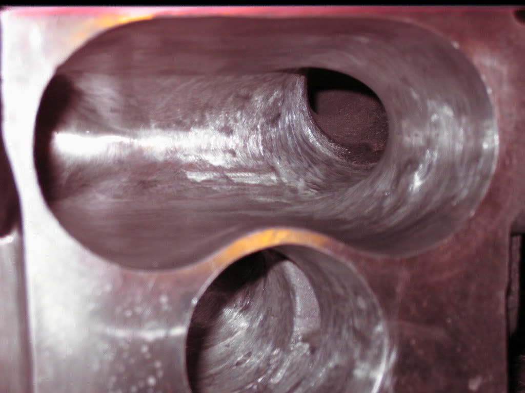
This is the FD UIM that i am prepping to go onto my car. It started as a JDM fd uim - unpolished. I went with the jdm one b.c it does not have that extra crap on the bottom....not sure what that was for anyway. Outside has been polished. Its not super shiny in the pictures b.c of all the dust. Note to self: port the inside first THEN polish the outside. Keeps you from having to polish the outside twice. Double throttle holes have been welded. I welded up/chopped off some other crap on the mani that i was not using. All of the vacuum holes have been welded shut except for the 3 on the turbo side of the engine. I wanted to be able to see the nice shiny aluminum plugs that i am putting in there. I will be running tapping the UIM with a 3/8 NPT tap and running a -10 line to a vacuum manifold. The port job consisted of matching the throttle body/uim gasket. The only reason i can see that mazda put that center support between the secondary plates was to mount the dual throttle. Since i dont have that anymore, i chopped it out. I will be knife edging the rear of the throttle body.
What it used to look like courtesy of the the thread by mono4lamar:
To the people with JDM uims: did you notice a big glob of metal on the primary runner on the rear of the engine? It was right where the runner opened up in the the plenum from which the 2 primary runners split off. Seemed a wierd place for a blob of metal, it looked like it was cast in there. I just ground it off. One other thing, did anyone grind off the little nub of metal under where the stud for the idle air control is? I didn't know how much material was there so i just smoothed it out. I didn't want to have to plug another hole.
Any ideas on the best way of smoothing out where i got a bit over zealous with the sand paper roll on the gasket mating surface? I only F'd up once but it did put a few scratches on the mating face. Should i even bother smoothing it out? Will the gasket just squish into the little scratches and seal correctly anyway? Would a piece of 320 grit sandpaper on a piece of glass be a good starting point for smoothing it out? Should i try some sort of lapping compound?
All the porting was done with a file, sandpaper rolls and a 3" disc sander. If i were to do this again i would get some rotary files b.c the sand paper rolls are painfully slow for somethings.
Polishing was done with a file for the big bumps, 3" disc sander for angle grinder, sand paper rolls, 220 and 320 greaseless compounds on spiral sewn buffing wheels, tripoli compound on a spiral sewn wheel and white rouge on a loose wheel.
I got most of my supplies from Eastwood.com. Total cost was about $110 for all the buffing and sanding stuff. I bought the angle grinder and 3" sander attachment at harbor freight.
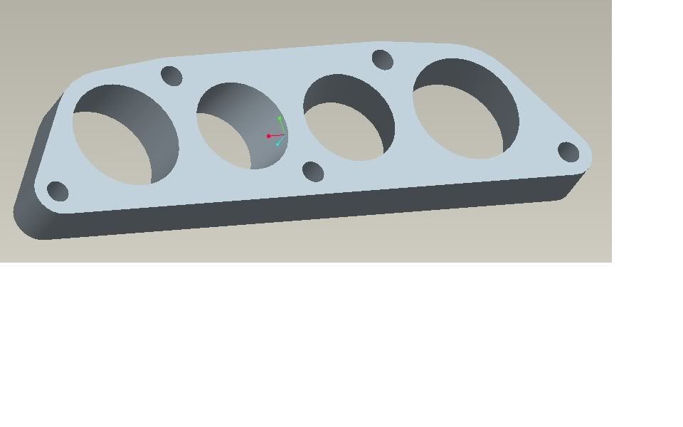
The manifold will be adapted by a spacer that i am having CNC'd. I did make a few extras....check the group buy interest thread, if i have enough interest ill make the s4 one as well. The spacer is meant to line up with the 2 gaskets. Here is the ProE rendering of it:
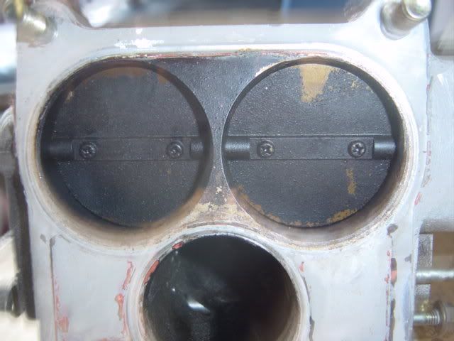
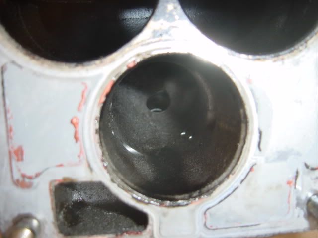
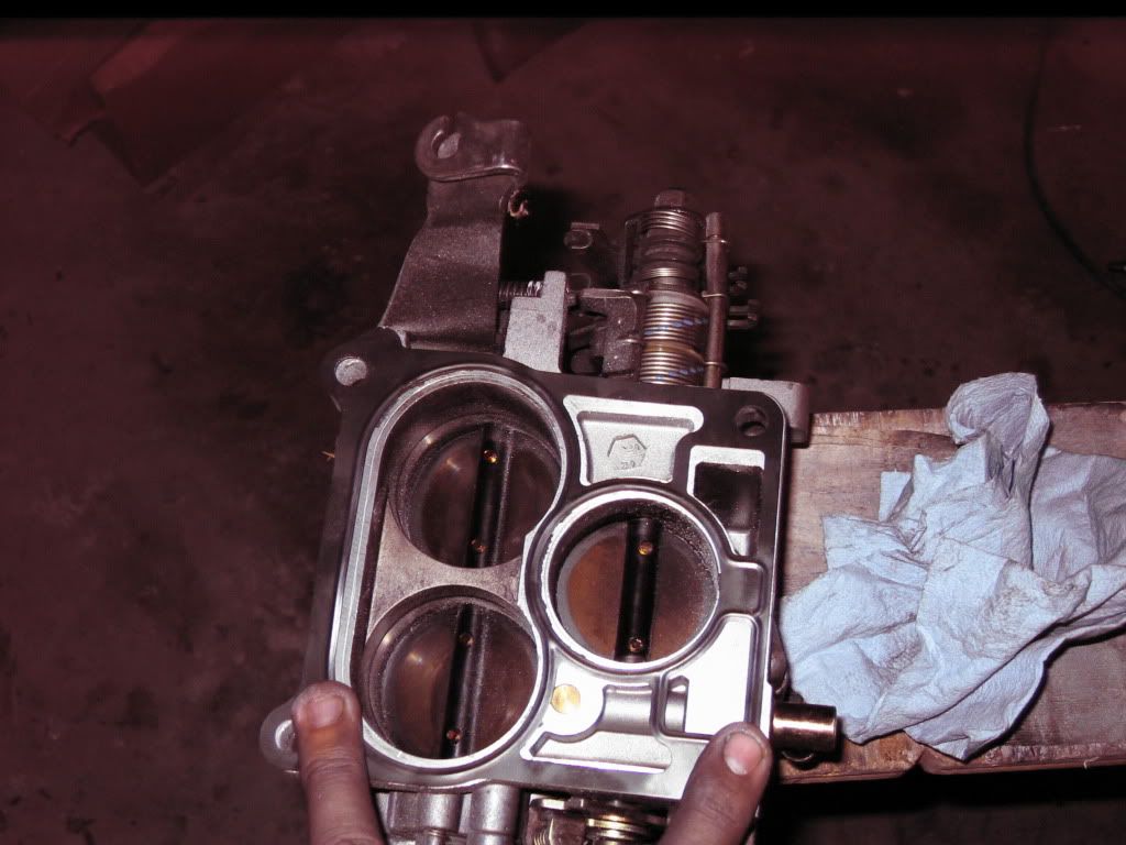
I have not gotten around to porting the tb yet. But here are a few before pics:
I am going to gasket/port match here
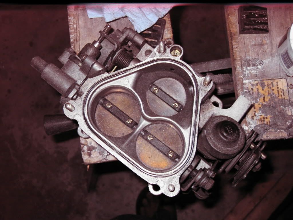
One quick question, how the hell do you get those god d@mn screws out of the tb. Mine are pretty stuck and all i am doing is F ing up the head of the screw. I just want to be able to strip off some of the crap that i dont need and mount my haltech TPS.
BTW, cost so far:
$55 JDM throttle body with out tps from Japan2LA
$75 JDM UIM from forum member
$11.29 FD UIM/LIM gasket from Mazdatrix
$3.87 S5 FC UIM/LIM gasket from Mazdatrix
-------------------
$145.16 (not including shipping from mazdatrix)
All that is left is to get the adapter plate, fabricate/buy an elbow and redo my cold side IC pipe.
The approximate cost of this swap (if you dont want the polished uim and you have your own tps) is $350 assuming you spend $5 on dremel bits for some port matching. If you need the FD tps it seems to cost about $20 more. Polished FD UIMs run around ~$200.
I got a bit long winded but i figured id show off what i have done and how i had done it. Also, yes i know the pictures look like they were taken in the 80s. Digital cameras dont like being left out when you are caught out in a storm when you are flats fishing.
Lee
What it used to look like courtesy of the the thread by mono4lamar:
To the people with JDM uims: did you notice a big glob of metal on the primary runner on the rear of the engine? It was right where the runner opened up in the the plenum from which the 2 primary runners split off. Seemed a wierd place for a blob of metal, it looked like it was cast in there. I just ground it off. One other thing, did anyone grind off the little nub of metal under where the stud for the idle air control is? I didn't know how much material was there so i just smoothed it out. I didn't want to have to plug another hole.
Any ideas on the best way of smoothing out where i got a bit over zealous with the sand paper roll on the gasket mating surface? I only F'd up once but it did put a few scratches on the mating face. Should i even bother smoothing it out? Will the gasket just squish into the little scratches and seal correctly anyway? Would a piece of 320 grit sandpaper on a piece of glass be a good starting point for smoothing it out? Should i try some sort of lapping compound?
All the porting was done with a file, sandpaper rolls and a 3" disc sander. If i were to do this again i would get some rotary files b.c the sand paper rolls are painfully slow for somethings.
Polishing was done with a file for the big bumps, 3" disc sander for angle grinder, sand paper rolls, 220 and 320 greaseless compounds on spiral sewn buffing wheels, tripoli compound on a spiral sewn wheel and white rouge on a loose wheel.
I got most of my supplies from Eastwood.com. Total cost was about $110 for all the buffing and sanding stuff. I bought the angle grinder and 3" sander attachment at harbor freight.
The manifold will be adapted by a spacer that i am having CNC'd. I did make a few extras....check the group buy interest thread, if i have enough interest ill make the s4 one as well. The spacer is meant to line up with the 2 gaskets. Here is the ProE rendering of it:
I have not gotten around to porting the tb yet. But here are a few before pics:
I am going to gasket/port match here
One quick question, how the hell do you get those god d@mn screws out of the tb. Mine are pretty stuck and all i am doing is F ing up the head of the screw. I just want to be able to strip off some of the crap that i dont need and mount my haltech TPS.
BTW, cost so far:
$55 JDM throttle body with out tps from Japan2LA
$75 JDM UIM from forum member
$11.29 FD UIM/LIM gasket from Mazdatrix
$3.87 S5 FC UIM/LIM gasket from Mazdatrix
-------------------
$145.16 (not including shipping from mazdatrix)
All that is left is to get the adapter plate, fabricate/buy an elbow and redo my cold side IC pipe.
The approximate cost of this swap (if you dont want the polished uim and you have your own tps) is $350 assuming you spend $5 on dremel bits for some port matching. If you need the FD tps it seems to cost about $20 more. Polished FD UIMs run around ~$200.
I got a bit long winded but i figured id show off what i have done and how i had done it. Also, yes i know the pictures look like they were taken in the 80s. Digital cameras dont like being left out when you are caught out in a storm when you are flats fishing.
Lee
09-16-09, 09:56 AM
#286
Rotary Enthusiast
Join Date: Mar 2007
Location: Pasadena
Posts: 1,485
Likes: 0
Received 0 Likes
on
0 Posts
Cool, thnaks for the pics. You forgot to mention the price of the adapter kit and the s5 t2 lim.  I'm just bitter because I tried selling my setup and people were lowballing me.
I'm just bitter because I tried selling my setup and people were lowballing me.
09-16-09, 10:42 AM
#287
Rotary Enthusiast
iTrader: (3)
Join Date: Jan 2007
Location: st. louis
Posts: 1,000
Likes: 0
Received 0 Likes
on
0 Posts
Sorry...Not giving that file out. I wasted way to much time getting things right (and i already know on thing that is wrong with it...doh... i forgot the relief for the bolts for the primary rail)
Price will be ~100. If the current design works, making one for a s4 or one that requires no port matching is trivial and i will do so if there is enough demand.
Price will be ~100. If the current design works, making one for a s4 or one that requires no port matching is trivial and i will do so if there is enough demand.
09-16-09, 01:06 PM
#288
Sorry...Not giving that file out. I wasted way to much time getting things right (and i already know on thing that is wrong with it...doh... i forgot the relief for the bolts for the primary rail)
Price will be ~100. If the current design works, making one for a s4 or one that requires no port matching is trivial and i will do so if there is enough demand.
Price will be ~100. If the current design works, making one for a s4 or one that requires no port matching is trivial and i will do so if there is enough demand.
Thanks Robert
 09-16-09, 06:11 PM
#294
Rotary Enthusiast
iTrader: (3)
Join Date: Jan 2007
Location: st. louis
Posts: 1,000
Likes: 0
Received 0 Likes
on
0 Posts
the top of the adapter plate will line up with the FD uim gasket. It then tapers and the bores shift to align with the FC uim gasket. This not just a 2D part. I did elect to not contour it against the FD uim as you did because it makes it more expensive.
Again, i made this to fit my car and i had a few extra made b.c i though people might want them, if you dont like it there are options for you to use. FC3S91's adapter plate looks quite well thought out. I would have bought his if i did not get satisfaction from designing and fabricating stuff for my own car.
Again, i made this to fit my car and i had a few extra made b.c i though people might want them, if you dont like it there are options for you to use. FC3S91's adapter plate looks quite well thought out. I would have bought his if i did not get satisfaction from designing and fabricating stuff for my own car.
09-16-09, 07:09 PM
#296
2jz'd fc
iTrader: (24)
Join Date: Jun 2005
Location: Washington- bellingham
Posts: 1,266
Likes: 0
Received 1 Like
on
1 Post
i drew and made my own at work, its actually going in the mill tomorrow. best part about it is im making it for FREE.....i love being able to use the cnc as i please. it has the shape of the lim and the holes are gasket matched and taperd. like you guys said there is so much more satifaction for making your own than buying. next on my list is hub centric wheel spacers
09-16-09, 10:00 PM
#297
i drew and made my own at work, its actually going in the mill tomorrow. best part about it is im making it for FREE.....i love being able to use the cnc as i please. it has the shape of the lim and the holes are gasket matched and taperd. like you guys said there is so much more satifaction for making your own than buying. next on my list is hub centric wheel spacers
Thanks Robert
09-16-09, 11:14 PM
#299
Rotary Enthusiast
i drew and made my own at work, its actually going in the mill tomorrow. best part about it is im making it for FREE.....i love being able to use the cnc as i please. it has the shape of the lim and the holes are gasket matched and taperd. like you guys said there is so much more satifaction for making your own than buying. next on my list is hub centric wheel spacers
09-16-09, 11:32 PM
#300
2jz'd fc
iTrader: (24)
Join Date: Jun 2005
Location: Washington- bellingham
Posts: 1,266
Likes: 0
Received 1 Like
on
1 Post
didnt get to finish the first post, my roommate wanted to use my comp. this one is more of my prototype, right now its machined down to square dimensions with the 5 mounting holes. the shape and ports will be done tomorrow hopefully. i totaly get the o-ring idea, woulda been nice to incorporate that into the first try. ill have to go hunt down the right sized o-rings and draw them up on the CAD file. thanks for the input