FD Upper on an Fc.

 06-07-09, 10:44 PM
#209
Retired Moderator, RIP
Thread Starter
iTrader: (142)
Join Date: Sep 2005
Location: Smiths Falls.(near Ottawa!.Mapquest IT!)
Posts: 25,581
Likes: 0
Received 131 Likes
on
114 Posts
If any of the guys that Have DONE this mod(fd Upper on a TII lower) can Give me the WIRING info for the FD TPS connector.
I need to wire the Connector to the Harness.
will the FD tps work with an RTEK?.( I need to know that too!)Thanks Guys.STYX.
I need to wire the Connector to the Harness.
will the FD tps work with an RTEK?.( I need to know that too!)Thanks Guys.STYX.
06-08-09, 01:57 PM
#210
Rotary Enthusiast
iTrader: (2)
Join Date: May 2005
Location: E-L Netherlands
Posts: 1,165
Likes: 0
Received 0 Likes
on
0 Posts
find the wiring diagrams for both tps sensors in the stickies.
colour codes are exactly the same for both, so just follow the diagram and you're set
for the FC you have 1 fullrange wire, 1 narrow range wire, 2 positive and 2 negative.
with the FD tps you have 1 of all, so you need to connect the positive and negative together
colour codes are exactly the same for both, so just follow the diagram and you're set
for the FC you have 1 fullrange wire, 1 narrow range wire, 2 positive and 2 negative.
with the FD tps you have 1 of all, so you need to connect the positive and negative together
06-14-09, 07:55 PM
#211
Series 4 TPS
-Orange - (+5V)
-Green/Red - Signal
-Black/Red - Ground
Series 5 TPS
- (2) Brown/Black - Ground
-Green/Red - Signal (Narrow range)
- (2) Brown/White - (5V+)
-Black/Green - Signal (Full range)
The ground and VREF wires are doubled in the harness in this particular build, because the car has two TPS units.
Series 6 TPS
-Brown/Black - Ground
-Green/Red - Signal (Narrow range)
-Brown/White - (5V+)
-Black/Green - Signal (Full range)
Got an enclosed TPS in your hands with no flying leads?
When looking directly at the FD TPS (when the push tab release is up), there are 4 pins.
1 - Ground
2 - Signal (Narrow range)
3 - (+5V)
4 - Signal (Full range)
It works with Rtek 2.1 for me.
The following users liked this post:
Mlammert (09-03-18)
06-17-09, 08:37 PM
#212
Rotary Enthusiast
Join Date: Mar 2007
Location: Pasadena
Posts: 1,485
Likes: 0
Received 0 Likes
on
0 Posts
I have a greddy FMIC. I need an elbow that doesnt point so close to the front.
Does anyone make a elbow for the fd throttle that points a little more towards the left side of the car, instead of going straight to the front?
Does anyone make a elbow for the fd throttle that points a little more towards the left side of the car, instead of going straight to the front?
06-17-09, 10:16 PM
#213
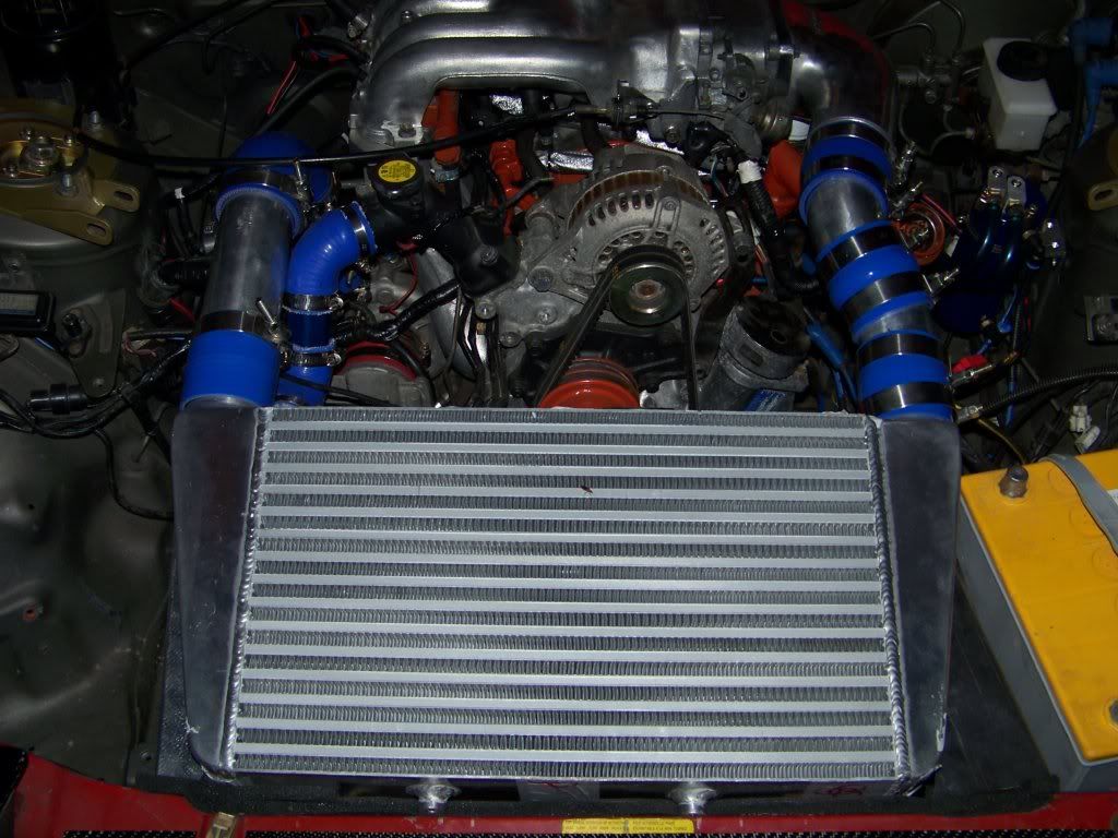
You want the piping to go more towards the fender right? Well if you look at all the FD setups they all have the GReddy compression tube and a bend to get the correct angle. That's what I ended up doing for my VMIC, you can cut what ever bends you need out of a J pipe. I actually had two make two small bends to get it just right. You can also see some of the new ducting around the radiator and intercooler in this pic.
06-17-09, 11:22 PM
#214
Rotary Enthusiast
Join Date: Mar 2007
Location: Pasadena
Posts: 1,485
Likes: 0
Received 0 Likes
on
0 Posts
the picture didn't load, it could be my comp. Yeah, I want it more towards the, but if those are the only elbows available, I'll just have to refabricate that section.
How much are those greddy elbows costing?
How much are those greddy elbows costing?
06-23-09, 07:48 PM
#215
The elbow from the 20B setup looks like the perfect shape but it probably doesn't fit the FD throttle body. I wanted mine to be a straight shot and was kinda surprised when the FD elbow came, it was more of a bend than I had planned for. The GReddy FD elbows are going for $90 shipped on here, $125 on e-bay.
06-25-09, 01:17 PM
#218
I have yet to get it on the street, I just got it running perfect last night, I had left a big hole in the LIM open and had a MASSIVE vac leak that kept stalling the engine. I put the bolt back in the hole and I have a perfect idle, hopefully we will be able to road test tomorrow.
I'd suggest trouble shooting just like you would if you had the FC UIM, check for vac leaks, make sure everything is tight, no boost leaks, etc....
I'd suggest trouble shooting just like you would if you had the FC UIM, check for vac leaks, make sure everything is tight, no boost leaks, etc....
07-11-09, 10:51 AM
#221
Retired Moderator, RIP
Thread Starter
iTrader: (142)
Join Date: Sep 2005
Location: Smiths Falls.(near Ottawa!.Mapquest IT!)
Posts: 25,581
Likes: 0
Received 131 Likes
on
114 Posts
Do you get a free Cheery with every Spacer?
..On another note.I got the whole she-bang together.I put the FD upper on.I got the IC mounted.
then I am going Hmm.what about the IAT sensor?.It is different.
GUYS: if you use the FD upper,you need a FD IAT sensor and a Connector.(.so,So far..FD TPS Connector,and FD IAT and connnector) to do this swap.
07-11-09, 05:55 PM
#222
Do you get a free Cheery with every Spacer?
..On another note.I got the whole she-bang together.I put the FD upper on.I got the IC mounted.
then I am going Hmm.what about the IAT sensor?.It is different.
GUYS: if you use the FD upper,you need a FD IAT sensor and a Connector.(.so,So far..FD TPS Connector,and FD IAT and connnector) to do this swap.
..On another note.I got the whole she-bang together.I put the FD upper on.I got the IC mounted.
then I am going Hmm.what about the IAT sensor?.It is different.
GUYS: if you use the FD upper,you need a FD IAT sensor and a Connector.(.so,So far..FD TPS Connector,and FD IAT and connnector) to do this swap.
 Im in the process of finding the connectors for the swap. So when I find them I will offer them on my website.
Thanks Robert
07-11-09, 07:45 PM
#223
Retired Moderator, RIP
Thread Starter
iTrader: (142)
Join Date: Sep 2005
Location: Smiths Falls.(near Ottawa!.Mapquest IT!)
Posts: 25,581
Likes: 0
Received 131 Likes
on
114 Posts
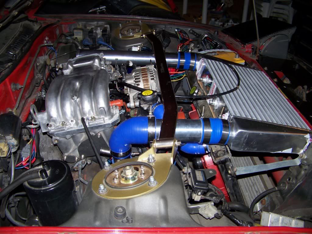
Here is MY Version.
I finally Discovered "manage Attachments"!!..Woot!
so,Finally!, here is my Project!..except for removing the N/A engine and dropping in the TII engine(thanks to Vipernicus42 for the extra set of hands.) I have done everything on my own.
Now,before I get criticism,all the Clamps are because they didn't make a 2 inch to 2.75 inch Coupler.
Cheers,Styx.
07-16-09, 09:11 PM
#225
Retired Moderator, RIP
Thread Starter
iTrader: (142)
Join Date: Sep 2005
Location: Smiths Falls.(near Ottawa!.Mapquest IT!)
Posts: 25,581
Likes: 0
Received 131 Likes
on
114 Posts
Thanks Robert!..I appreciate the "critique"!
I am bumping this Up.Some Lads have been asking about this swap...(hey,you may get some Business out of it!)
I am bumping this Up.Some Lads have been asking about this swap...(hey,you may get some Business out of it!)