
separating fiction from reality... a couple of days on the DYNO

talking head
Joined: Apr 2008
Posts: 2,775
Likes: 15
From: Perth, WA, OZ
i expect the driver transistor has died
,, and you need an average electronics repair guy to ID the burnt driver as darlington, mosfet or IGBT
,,, raid the farnell catalogue
and hopefully replace with equivalent that is board mount in the same dimensions
i have done this to some older micro ECU's in the past
( the bastards grind off the transistor ID's to make a $10 fix into several hundred $$ )
though the replacements i found ( darlington ) don't fit the PCB mounts and had to be creatively wired to the board
however,, not all fails claim the driver
holding the PCB up to the light should highlight any burned or lifted tracks
- ,, easily bridged around -


Some battery chargers tend to cause brief high voltage spikes. I'm having trouble finding a reference online, but I think I've heard some people claim that it may be better to send brief high-voltage spikes when charging a battery, the explanation was that it either decreases required charging time or that it may remove deposits inside old cells.
It's possible your new charger may be related to the electronics failures you've experienced. Personally, I'd keep a trickle charger on the car if it's sitting for a long period of time but I wouldn't have a high-current charger on the car at all times, especially not in 'crank/start assist' mode.
As mentioned by others, bad things can happen if the battery's terminals have an intermittent connection. There could also be a problem if the plastic connector on the side of the alternator is not secure, so it's not a bad idea to double-check that.
For storage batteries used with solar powered systems, I have read that using chargers that put out frequent controlled spikes helps to increase the life of the lead cell batteries. It helps to break up/dissolve crystals on the lead plates. Such solar systems are made to handle high correct flow rates throughout all components.
Cars are not.
Cars are not.
Thread Starter
Joined: Oct 2001
Posts: 6,279
Likes: 728
From: Florence, Alabama
update
my two Power FCs are in Ca at Apexi and will be diagnosed early this week. if they both suffer from torched injector drivers, as i suspect, they get to go to Japan for fixes. a couple of months.
in the interim MannyKiller has graciously (and foolishly) consented to send me his Power FC. just kidding on the foolishly Aaron. really.
i have a proper relay in place so i doubt i will see any further volt spikes. further i should receive tomorrow a bunch of Varistors that get wired in parallel in front of all the solid state modules. that should end my electronic problems.
meanwhile i did some additional research on my meth pump (Bosch 044 variant) and have decided to look elsewhere as it falls on it's face around 80 psi.
i will be going back to a gussied up Shurflo probably. the 1.8 GPM open flow pump should be able to run the two Bosch EV14 1000 cc/min meth injectors at 86 psi static and also at top turbo boost (30) which would be 116.
the EV14 injectors will work fine to 8 Bar (116 psi) and will deliver approx 2800 CC/Min of meth.
here are a few pics/comments relating to the new AI system:
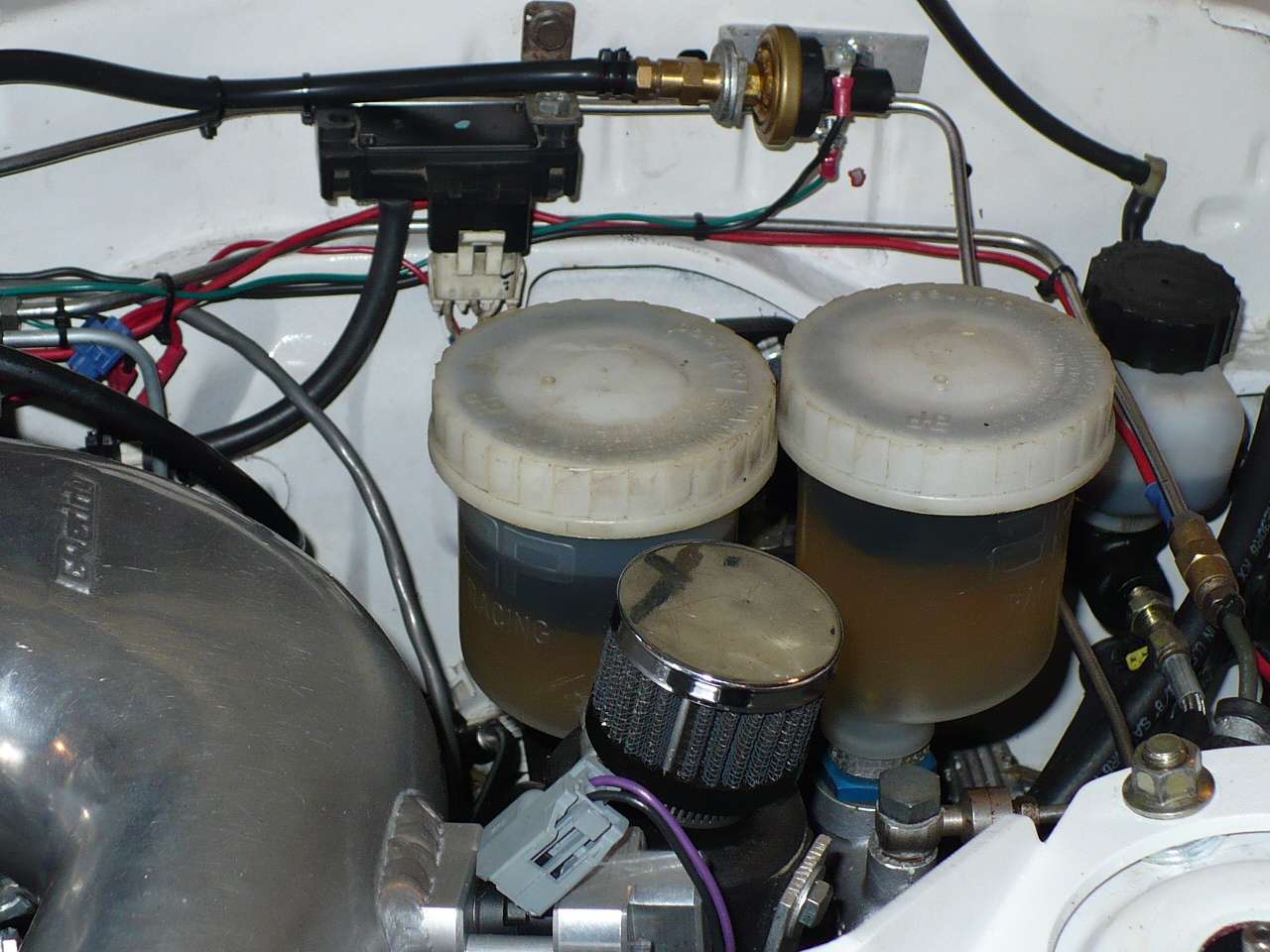
you can see 3 items in the pic... one of the two fuel injectors that will deliver the meth. (the other is underneath at 6 o'clock)
my adj Honeywell boost switch on the firewall. it is set to trigger the meth pump at 1.5 psi boost and is tapped in to the UIM.
a stainless steel 3/16 brakeline that connects the adj meth pressure regulator and MAP from the UIM. the regulator is in the rear of the car by the pump and tank.

while this might look like a mish mash it does show an important component in the center of the picture... a meth pressure logger/sensor that is hooked into my Datalogit. i consider logging fuel pressure and meth pressure essential.
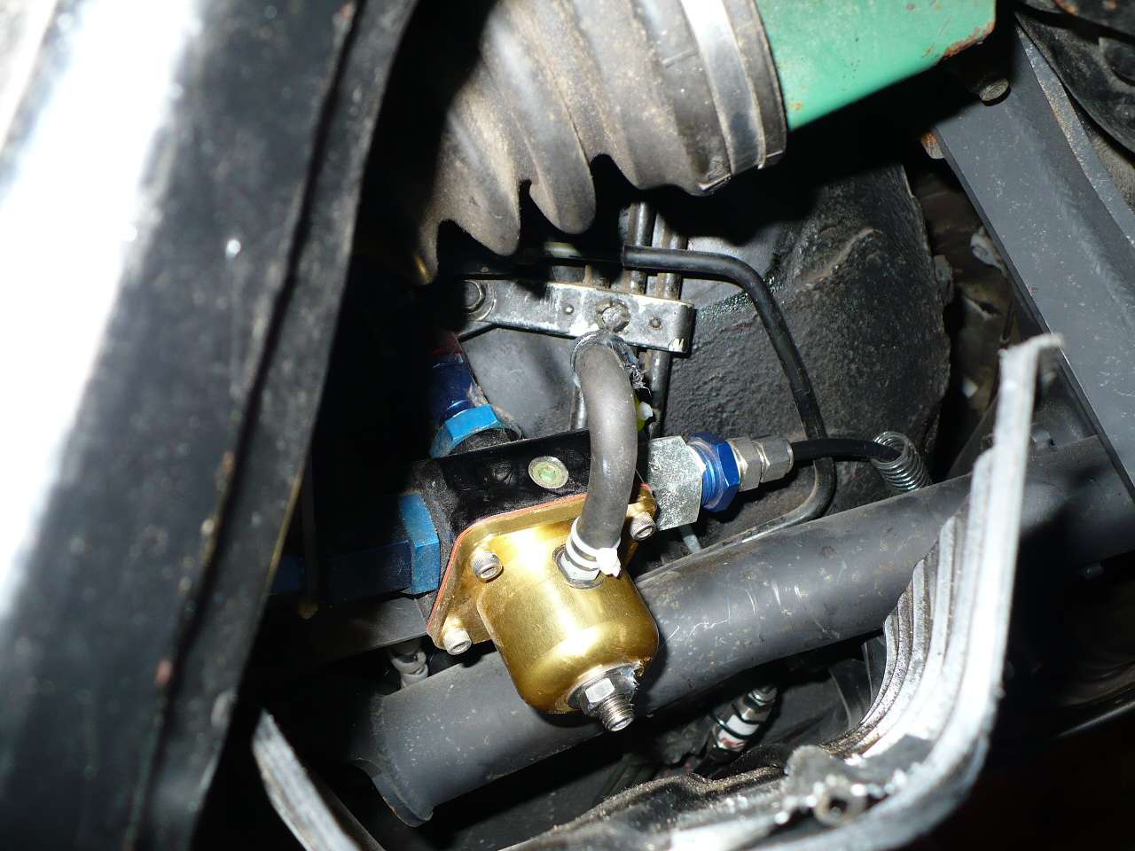
my Weldon meth friendly adj pressure regulator. located near/above the driver's side half shaft. it features a return line to the meth fuel cell and is plumbed in to the engine's MAP. if you look forward you will spot a meth filter.
here are a few engine bay pics. since i have had the UIM off and on and haven't buttoned it up you will notice the FPR isn't bolted down and the Garfinkle Engine Torque brace is missing.

i repositioned yet again my two FJO modules.. the driver's side is the Peak and Hold convertor that is being used to take the load off the Power FC as to running 4 secondary injectors while the other module is the Wide Band.

another shot of the Borg Warner turbo. at 22.4 pounds this should be the heaviest turbo in the test. my manifold design seeks to postion the turbo as close to the combustion chamber as possible. this wouldn't have been possible without the MICA HEATSHIELD. seen in the next pic/ i do like how the turbo relates to the intercooler. a very short shot and straight in. it is all about flow.

here's another view of the Mica shield. while the turbine is within 3/8 inch of the shield almost no heat penetrates. i also feel it is helpful to position the longitudinal center of the turbine w the center of the engine using short runners.

if you look carefully you will see the Tial 60 mm wastegate. it is positioned so as to locate the heat sensitive end away from the heat in the center of the front lower A arm. it has a straight shot at a mild angle into the downpipe. my logs show my back pressure averaging 86% of boost pressure.

as previously mentioned, it is all about flow... i feel it is very important to not butcher the pipe from the intercooler to the Greddy elbow. butcher as in locating a big 2 inch hole in it for the BOV. my BOV is located on a flat unimportant endtank area on the IC.
no big deal here but i thought i would post a few pics...
howard
my two Power FCs are in Ca at Apexi and will be diagnosed early this week. if they both suffer from torched injector drivers, as i suspect, they get to go to Japan for fixes. a couple of months.
in the interim MannyKiller has graciously (and foolishly) consented to send me his Power FC. just kidding on the foolishly Aaron. really.
i have a proper relay in place so i doubt i will see any further volt spikes. further i should receive tomorrow a bunch of Varistors that get wired in parallel in front of all the solid state modules. that should end my electronic problems.
meanwhile i did some additional research on my meth pump (Bosch 044 variant) and have decided to look elsewhere as it falls on it's face around 80 psi.
i will be going back to a gussied up Shurflo probably. the 1.8 GPM open flow pump should be able to run the two Bosch EV14 1000 cc/min meth injectors at 86 psi static and also at top turbo boost (30) which would be 116.
the EV14 injectors will work fine to 8 Bar (116 psi) and will deliver approx 2800 CC/Min of meth.
here are a few pics/comments relating to the new AI system:
you can see 3 items in the pic... one of the two fuel injectors that will deliver the meth. (the other is underneath at 6 o'clock)
my adj Honeywell boost switch on the firewall. it is set to trigger the meth pump at 1.5 psi boost and is tapped in to the UIM.
a stainless steel 3/16 brakeline that connects the adj meth pressure regulator and MAP from the UIM. the regulator is in the rear of the car by the pump and tank.
while this might look like a mish mash it does show an important component in the center of the picture... a meth pressure logger/sensor that is hooked into my Datalogit. i consider logging fuel pressure and meth pressure essential.
my Weldon meth friendly adj pressure regulator. located near/above the driver's side half shaft. it features a return line to the meth fuel cell and is plumbed in to the engine's MAP. if you look forward you will spot a meth filter.
here are a few engine bay pics. since i have had the UIM off and on and haven't buttoned it up you will notice the FPR isn't bolted down and the Garfinkle Engine Torque brace is missing.
i repositioned yet again my two FJO modules.. the driver's side is the Peak and Hold convertor that is being used to take the load off the Power FC as to running 4 secondary injectors while the other module is the Wide Band.
another shot of the Borg Warner turbo. at 22.4 pounds this should be the heaviest turbo in the test. my manifold design seeks to postion the turbo as close to the combustion chamber as possible. this wouldn't have been possible without the MICA HEATSHIELD. seen in the next pic/ i do like how the turbo relates to the intercooler. a very short shot and straight in. it is all about flow.
here's another view of the Mica shield. while the turbine is within 3/8 inch of the shield almost no heat penetrates. i also feel it is helpful to position the longitudinal center of the turbine w the center of the engine using short runners.
if you look carefully you will see the Tial 60 mm wastegate. it is positioned so as to locate the heat sensitive end away from the heat in the center of the front lower A arm. it has a straight shot at a mild angle into the downpipe. my logs show my back pressure averaging 86% of boost pressure.
as previously mentioned, it is all about flow... i feel it is very important to not butcher the pipe from the intercooler to the Greddy elbow. butcher as in locating a big 2 inch hole in it for the BOV. my BOV is located on a flat unimportant endtank area on the IC.
no big deal here but i thought i would post a few pics...
howard

I'm not very familiar with PowerFCs, but if I had two different ECUs with a failure on the same injector driver, I would seriously consider replacing that injector and running brand new wires to it. If this is more time and effort than you want to spend, at least swap the front and rear primary injectors (label them carefully)... if your next ECU loses the rear injector driver it is likely a problem with that injector, and if it loses the front injector driver it is likely a problem with the wiring for the front injector.

Trial and error takes time. It's not like this lone project is his full time job and is the only thing he is doing all day. Howard is a standup guy who is doing things in a very methodical calculated way. Feel lucky he is showing anything off at all. There are lots of people out there who are much like him that no one has ever heard about for the simple reason that they don't share their work due to the ridicule that hiding behind a computer screen seems to bring out in people.
I think the thread should be edited to remove all posts except the first about what Howard is trying to do and his failures along the way. That way we do not need to read through 637 posts where most of them are trash.
Thread Starter
Joined: Oct 2001
Posts: 6,279
Likes: 728
From: Florence, Alabama
Update:
finally out of the barn


I am happy to report that I have successfully dealt w a number of problems that surfaced approx Sep 1.
After a brief run on the rollers Aug 3, during which we lost the methanol AI delivery, I drove the car (90 miles) home and spent a month re-engineering a number of items.
This included wiring (in parallel to the secondaries) a set of Bosch EV14 fuel injectors to deliver the methanol. The injectors are run by the Power FC, the pump being triggered by a Honeywell adj boost switch. The meth injectors are actually powered by an FJO Peak and Hold module to take the draw off the power FC.
I also switched out my Bosch inline (external) 044 meth pump for an AlkyControl unit that delivers more at 8 Bar pressure while drawing 6 less amps.

Upon startup, around the first of Sep, the engine ran very roughly and pumped white clouds out the exhaust. I looked at my watches and noticed the rear egt was showing around 55 degrees F while the front egt was showing 500 or thereabouts. I concluded the motor was running on the front rotor.
I swapped the primary injectors (front to rear) and found the same deal� no heat in the rear rotor. I had recently installed a new wiring harness so I didn�t spend much time tracing continuity to the primaries but did check the injectors w a node light. They checked out as did the ignition.
given my succession of fried electronic modules i assumed it was the Power FC.
Looking at the plugs further provided confusing data as they looked similar.
Meanwhile clouds are coming out of the tailpipe. When we lost the alcohol on the dyno we were at 20 psi so I was concerned re a lost coolant seal. I placed a window pane very close to the tailpipe and ran the motor for a few minutes and then looked at the condensate� sure looked like coolant.
What was weird is that the motor ran fine all the way home from the dyno� no smoking.
After discussing my situation w Ari Y, I elected to send my Power FC (actually two of them) back to Apexi for service in Japan. �probably a blown injector driver?
I pulled the motor, and spent a considerable time looking for a breached seal� I really am not sure I found one. the motor was fine overall so I added new seals, decided to re-install my NRS ceramic one piece seals and swapped in a set of Mazda corner seals as they have a better sized slot for my ceramics.
Back together I pressured the motor�s cooling system w 32 psi of air and let it sit for 9 hours. upon return the gauge read a solid 32.
Upon startup, no white clouds out the exhaust but a ragged running motor� looking on my logged MAP I noticed that the data was logging on only one (horizontal) X line�P line.
Maybe my GM 3 Bar MAP sensor?... I checked it was getting 4.5 V, yup. I checked the ground was grounding, yup. I checked the signal wire had continuity to where it entered the Power FC (borrowed from a friend), yup. I disconnected the MAP rubber line from the UIM and pressured it up and checked V output to the Power FC. Yup. Last Sat I hit a boneyard and grabbed another MAP sensor and swapped it in and the data continued on one line.
I loaded a bunch of MAPS and the car continued to run on one rotor and the data one lined. Finally on one loaded map the motor ran smoothly! The PIM numbers and offset were weird numbers� around 5000 w a 5000 offset. The motor wouldn�t run well above the idle area but it did run on both rotors or so I thought.
My egt readings continued to indicate the rear rotor was cold.
The light bulb (finally) switched on. It now looked like my motor probably had been running on both rotors, but roughly. I swapped emails w Ari about my Datalogit and the one line output. He couldn�t think of any setting or condition that would cause the problem.
That was last Sunday. Finally I asked the question� if all the electrics (Map sensor, Datalogit, Power FC, wiring) were fine what would cause the logging to take place on one line�
Maybe the MAP sensor was reporting accurately. Maybe it was getting just one atmospheric reading.
Maybe I should check this:

Last Sunday night I bolted back out to the shop, yanked the hose off the MAP sensor, connected it to a Vacuum/pressure gauge and started the engine.
The needle didn�t move!
My brand new silicone MAP hose was plugged to the MAP sensor. Double tie wrapped but plugged. I had added a dab of RTV after double tie wrapping them and apparently I brushed the RTV w the tip of the MAP sensor hose.
That of course caused the MAP sensor to duly report to the Power FC one reading. so the engine is trying to idle but the settings were for atmospheric pressure not vacuum. That�s why the weird PIM settings worked as they were close to the vacuum condition of the motor at idle.
So it turns out my motor wasn�t running on one rotor, rather the Power FC was not getting proper readings from the manifold.
Yikes.
A couple of days earlier Apexi called to tell me the Power FCs had arrived back from Japan and they completely checked out. That squares w Ari telling me very very few Power FCs have had driver problems. Especially when running a setup similar to mine.
They arrived today and my newer one will go back in the car.

I did swap in a proper relay so my modules should not have voltage spike problems. I also have a varistor in front of my Power FC. (I bet the Power FC has a varistor internally).
Since Beyond Redline is 90 miles N and winter generally starts Dec 1 I have been paying close attention to the weather. I will not drive my car on salted roads. It is clean on the bottom side as it is on the top and will remain that way. We have yet to have a real snow (amazingly) but it is predicted for tomorrow and off and on going forward.
I will have to arrange for my car to be transported back up to B R. Christmas will soon be upon us so I will call Luke and hope we can arrange transport the following week.
I did manage to put 20 miles on the car yesterday and logged some data. My meth is coming on correctly and all the metrics look good.
I do apologize for my lack of updates but I just decided to focus on my problems and only report after solutions were in hand.
The turbo project will move forward. As the months/years roll by there continues to be more interesting turbo options and I hope to snag a few but my focus is on getting the first one evaluated.
howard
finally out of the barn
I am happy to report that I have successfully dealt w a number of problems that surfaced approx Sep 1.
After a brief run on the rollers Aug 3, during which we lost the methanol AI delivery, I drove the car (90 miles) home and spent a month re-engineering a number of items.
This included wiring (in parallel to the secondaries) a set of Bosch EV14 fuel injectors to deliver the methanol. The injectors are run by the Power FC, the pump being triggered by a Honeywell adj boost switch. The meth injectors are actually powered by an FJO Peak and Hold module to take the draw off the power FC.
I also switched out my Bosch inline (external) 044 meth pump for an AlkyControl unit that delivers more at 8 Bar pressure while drawing 6 less amps.
Upon startup, around the first of Sep, the engine ran very roughly and pumped white clouds out the exhaust. I looked at my watches and noticed the rear egt was showing around 55 degrees F while the front egt was showing 500 or thereabouts. I concluded the motor was running on the front rotor.
I swapped the primary injectors (front to rear) and found the same deal� no heat in the rear rotor. I had recently installed a new wiring harness so I didn�t spend much time tracing continuity to the primaries but did check the injectors w a node light. They checked out as did the ignition.
given my succession of fried electronic modules i assumed it was the Power FC.
Looking at the plugs further provided confusing data as they looked similar.
Meanwhile clouds are coming out of the tailpipe. When we lost the alcohol on the dyno we were at 20 psi so I was concerned re a lost coolant seal. I placed a window pane very close to the tailpipe and ran the motor for a few minutes and then looked at the condensate� sure looked like coolant.
What was weird is that the motor ran fine all the way home from the dyno� no smoking.
After discussing my situation w Ari Y, I elected to send my Power FC (actually two of them) back to Apexi for service in Japan. �probably a blown injector driver?
I pulled the motor, and spent a considerable time looking for a breached seal� I really am not sure I found one. the motor was fine overall so I added new seals, decided to re-install my NRS ceramic one piece seals and swapped in a set of Mazda corner seals as they have a better sized slot for my ceramics.
Back together I pressured the motor�s cooling system w 32 psi of air and let it sit for 9 hours. upon return the gauge read a solid 32.
Upon startup, no white clouds out the exhaust but a ragged running motor� looking on my logged MAP I noticed that the data was logging on only one (horizontal) X line�P line.
Maybe my GM 3 Bar MAP sensor?... I checked it was getting 4.5 V, yup. I checked the ground was grounding, yup. I checked the signal wire had continuity to where it entered the Power FC (borrowed from a friend), yup. I disconnected the MAP rubber line from the UIM and pressured it up and checked V output to the Power FC. Yup. Last Sat I hit a boneyard and grabbed another MAP sensor and swapped it in and the data continued on one line.
I loaded a bunch of MAPS and the car continued to run on one rotor and the data one lined. Finally on one loaded map the motor ran smoothly! The PIM numbers and offset were weird numbers� around 5000 w a 5000 offset. The motor wouldn�t run well above the idle area but it did run on both rotors or so I thought.
My egt readings continued to indicate the rear rotor was cold.
The light bulb (finally) switched on. It now looked like my motor probably had been running on both rotors, but roughly. I swapped emails w Ari about my Datalogit and the one line output. He couldn�t think of any setting or condition that would cause the problem.
That was last Sunday. Finally I asked the question� if all the electrics (Map sensor, Datalogit, Power FC, wiring) were fine what would cause the logging to take place on one line�
Maybe the MAP sensor was reporting accurately. Maybe it was getting just one atmospheric reading.
Maybe I should check this:
Last Sunday night I bolted back out to the shop, yanked the hose off the MAP sensor, connected it to a Vacuum/pressure gauge and started the engine.
The needle didn�t move!
My brand new silicone MAP hose was plugged to the MAP sensor. Double tie wrapped but plugged.
I had added a dab of RTV after double tie wrapping them and apparently I brushed the RTV w the tip of the MAP sensor hose.That of course caused the MAP sensor to duly report to the Power FC one reading. so the engine is trying to idle but the settings were for atmospheric pressure not vacuum. That�s why the weird PIM settings worked as they were close to the vacuum condition of the motor at idle.
So it turns out my motor wasn�t running on one rotor, rather the Power FC was not getting proper readings from the manifold.
Yikes.
A couple of days earlier Apexi called to tell me the Power FCs had arrived back from Japan and they completely checked out. That squares w Ari telling me very very few Power FCs have had driver problems. Especially when running a setup similar to mine.
They arrived today and my newer one will go back in the car.
I did swap in a proper relay so my modules should not have voltage spike problems. I also have a varistor in front of my Power FC. (I bet the Power FC has a varistor internally).
Since Beyond Redline is 90 miles N and winter generally starts Dec 1 I have been paying close attention to the weather. I will not drive my car on salted roads. It is clean on the bottom side as it is on the top and will remain that way. We have yet to have a real snow (amazingly) but it is predicted for tomorrow and off and on going forward.
I will have to arrange for my car to be transported back up to B R. Christmas will soon be upon us so I will call Luke and hope we can arrange transport the following week.
I did manage to put 20 miles on the car yesterday and logged some data. My meth is coming on correctly and all the metrics look good.
I do apologize for my lack of updates but I just decided to focus on my problems and only report after solutions were in hand.
The turbo project will move forward. As the months/years roll by there continues to be more interesting turbo options and I hope to snag a few but my focus is on getting the first one evaluated.
howard
Glad it is figured out!
I had let Gasgacinch dry till tacky on the nipples and zip tied on the vacuum caps for the FD UIM primary runner.
The gasgacinch hardened up over time and one cap blew off.
A fellow racer noticed it after the race and lent me cap since he lived very close to the track.
I think a true dual fuel system for Methanol as you have done is the only right way to do it!
Nice work.
I pulled the motor, and spent a considerable time looking for a breached seal� I really am not sure I found one. the motor was fine overall so I added new seals, decided to re-install my NRS ceramic one piece seals and swapped in a set of Mazda corner seals as they have a better sized slot for my ceramics.
Back together I pressured the motor�s cooling system w 32 psi of air and let it sit for 9 hours. upon return the gauge read a solid 32.
New housings correct?
Thread Starter
Joined: Oct 2001
Posts: 6,279
Likes: 728
From: Florence, Alabama
"Im assuming you pressure tested the engine before tear down as well? If so, did it not hold pressure?"
yes.
Cam thought it might be a one way leak... it did seem to act that way as i did get bubbles in the Lisle funnel.
housings were perfect and were re-honed by Cam. compression is on the money ATM.
hc
yes.
Cam thought it might be a one way leak... it did seem to act that way as i did get bubbles in the Lisle funnel.
housings were perfect and were re-honed by Cam. compression is on the money ATM.
hc

Joined: Mar 2001
Posts: 31,859
Likes: 3,243
From: https://www2.mazda.com/en/100th/
wow MR Murphy has been busy!
My friend has an engine with an intermittent coolant seal leak, it can be fine for a week or so, and then its really bad, and then its fine again. its an old FC engine, so suspect the water seal is ok, but one of the irons is bad
good luck!
My friend has an engine with an intermittent coolant seal leak, it can be fine for a week or so, and then its really bad, and then its fine again. its an old FC engine, so suspect the water seal is ok, but one of the irons is bad
good luck!
"Im assuming you pressure tested the engine before tear down as well? If so, did it not hold pressure?"
yes.
Cam thought it might be a one way leak... it did seem to act that way as i did get bubbles in the Lisle funnel.
housings were perfect and were re-honed by Cam. compression is on the money ATM.
hc
yes.
Cam thought it might be a one way leak... it did seem to act that way as i did get bubbles in the Lisle funnel.
housings were perfect and were re-honed by Cam. compression is on the money ATM.
hc
I had a customer bring me an FD years ago that would hold pressure all day long. But when you got it warm and shut it off it would lose coolant into one of the housings. One start up you got the white smoke. No amount of pressure testing would show the leak. Ended up, with the engine apart, it had a cracked o-ring land and the issue was visually obvious.
