
separating fiction from reality... a couple of days on the DYNO


This is why Injector Dynamics has their own horsepower calculator that factors in deadtime, fuel pressure, recovery time, etc. giving a very accurate representation of horsepower potential. Most other online injector calculators fail to include these variables, which is one of the many reasons we prefer Injector Dynamics injectors.
http://www.injectordynamics.com/HPCalculator.html
http://www.injectordynamics.com/HPCalculator.html
Rotary Freak
Joined: Dec 2001
Posts: 2,402
Likes: 0
From: chandler, AZ
a good day for me is when i learn something
as you may be aware, i am in the middle of re-tooling my AI system since my irreplaceable FJO system decided to check out.
it should be a win for me and for Power FC owners as it uses the Power FC to drive an additional pair of new generation Bosch EV14 injectors in the elbow to spray methanol. (you could use water or a mix too).
i premise many of my calculations on an empirically derived relationship between rotary rwhp and airflow. if you know the airflow and AFR you can calculate fuel and lots of other interesting numbers.
it appears i have omitted a key additional deduct going from gross fuel to net fuel:
that factor is injector Lag, often also referred to as Deadtime.
i have read about it many times and we all input lag numbers when we set up our Power FC Settings 5 page.
i guess the lightbulb never quite turned on for me until it was brought to my attention by a board member and after i did some calculations...
i referred back to a previous run for numbers. here's how it played out...
507 rw hp SAE
12.0 AFR
75.1 injector duty
20 PSI
injectors:
primary 888 (RC flowed)
secondary 1650 (RC flowed)
secondaries run by an FJO Peak and Hold converter
Supra pump run by Kenne Bell Boost A Pump at 20% Volt gain
AI
Net delivery of 1128 CC/Minute of 100% methanol at 20 psi
let's now try to quantify the amount of fuel loss from LAG/Deadtime
507 rw rotary hp X 1.92 = 973 CFM/14.471 = 67.24 pounds of air per minute
at 12.0 AFR.... 67.24/12 = 5.603 pounds of gasoline per minute
5.603/6.35 (weight per gallon gas) = .882 gallons per minute
.882 X 116,090 (BTUs in a gallon of gas) = 102,448 BTUs to make 507
BTUs from AI system
two M10 nozzles. Gross deliverability 1262 CC/Min. at 20 PSI boost X .89 (reduction due to manifold pressure) = 1128 CC/Minute Net
1128 CC/Min = .298 Gallons per minute X 57,250 (BTUs in a gallon of methanol) = 17,060 BTUs from AI
102,448 (BTUs to make 507 hp) - 17,060 BTUs from meth = 83,388 BTUs needed from gas to make 507.
BTUs from gasoline
According to my Gross Deliverability (5060) times my duty cycle (.751) i was nominally at (3800 CC) /116,438 BTUs.
116,438 - 85,388 = 31,050 the slippage from Lag/Deadtime
31,050/116,438 = 26.6% deduct
i will be off the board in the wilds of Wyoming this next week while Beyond Redline fixtures my elbow. i should have it the following Monday and hope to be on the dyno that week.
it will be very interesting to acquire some additional data as to Lag/Deadtime.
Lag/DT will vary w re to RPM, ontime (Deadtime is actually constant throughout RPM range and ontime), battery voltage, type of injector, fuel viscosity/temperature but from my calculations it may be a really important factor to crank into fuel system requirements as far as getting to NET Fuel Delivery.
Exactly. However, you just pointed out another variable missing in your calculations with viscosity. RC and almost all other injector suppliers test with a "calibrated test fluid," usually mineral spirits. This is important because you are directly converting RC's FLOW rates to BTU's. However, you started calculating your engine's fuel consumption with BTU's from POUNDS of gasoline. This is only accurate if they tested the injectors with gasoline. Mineral spirits has a higher viscosity than gasoline. Just to clarify, think about the weight of motor oil that would flow through an injector vs. the weight of water that could flow through the same injector.
injectors generally come w Lag settings to compensate so proper fuel is delivered throughout the range... so the settings portion is handled.
my concern is that when figuring fuel requirements perhaps another 20-25% needs to be added so as not to run short. if that number is in the ballpark it is an eyeopener.
comments welcome.
Joined: May 2005
Posts: 2,745
Likes: 0
From: North Bay, Ontario
But, methanol (the fuel he is planning on running through 2 of the injectors) will have nearly the same viscosity as the mineral spirits, and therefore the ID1000's will inject slightly more, right?
P.S., can someone explain the ID fuel maps. I can't figure out if fuel flow is directly related to Pulse width in ms (independent of RPM, but limited to 100% duty cycle) or Duty cycle in % (dependent on RPM)
P.S., can someone explain the ID fuel maps. I can't figure out if fuel flow is directly related to Pulse width in ms (independent of RPM, but limited to 100% duty cycle) or Duty cycle in % (dependent on RPM)

This is why Injector Dynamics has their own horsepower calculator that factors in deadtime, fuel pressure, recovery time, etc. giving a very accurate representation of horsepower potential. Most other online injector calculators fail to include these variables, which is one of the many reasons we prefer Injector Dynamics injectors.
http://www.injectordynamics.com/HPCalculator.html
http://www.injectordynamics.com/HPCalculator.html
I really like this calculator.
http://www.maxcooper.com/rx7/how-to/...tem/calcs.html
Also, Howard, I would like your opinion on something if you don't mind. I might have figured out how to adjust fuel vs ethanol content on the PFC, however I don't think there's a way to do IGN. If you run e85, odds are you will have an aftermarket secondary rail, eliminating the fuel temp sensor that resides in the stock rail. If you convert that signal to read from a 0-5v output from the e85 content sensor (found in GM, Ford, and other FFVs) and do some math to figure out which temps relate to what voltage, you can figure out how to adjust the injector flow. Settings 2.

The stated test condition is 100Hz. To find the available time for injection, take time and divide it by rate of injections.
1000mS is one second.
1000mS / 100Hz = 10mS spacing cycle to cycle.
In a fully sequential rotary 100Hz of injection would technically be 1 injector squirt per rpm, whereas a fully sequential piston engine would have 1 injector squirt per 2 rpm.
This means the test condition stated at 100Hz means 6000RPM for a fancy ECU, or 3000RPM if you have batch fired injection.
So technically the ID graph showing maximum linear duty, you use the 1 rev per injection for a sequential ecu. For the case of a batch fired rotary you would double the distance from 100% for 2 injections per rpm.
Trots - Mineral spirits is more viscous than gasoline or methanol, so will still be somewhat inaccurate.
KKMpunkrock2011 - do the primary and secondaries separately. Use the calculator for 2x ID1000's to figure out potential horsepower, then repeat for the 2000's and add them together.
As Jobro stated, the ID graphs are @100hz, so 10msec equals 100% duty cycle at 6000rpms for single rev per injection like the rotary.
The maxcooper calc is easy to use, but I think those BSFC are fairly unrealistic. It also leaves out how RPM, dead times, or recovery times could effect things..
Like a .84 A/R T4 flows more than say a T3 1.05 A/R.
This is b/c a true T4 has a larger area.
Which is what you are talking about I believe.
That being said - I would argue it all depends on application again which is why we have so many damn choices to begin with.
Aspec sells both a T3 and T4 turbo and for good reasons. It's because better is merely a perspective.
When you state that a .84 A/R flows more than a T3 1.05 AR housing this may indeed be true however, I am not sure if you have considered the turbine wheel as a possible choke point to flow.
If the wastegate is regulating the turbine wheel 100,000rpm and both the T4 and T3 housings have the same "P" trim exhaust wheel in them the 1.05 A/R of the T3 housing would be forcing less work out of the exhaust gas to pass through the exhaust wheel.
Is it possible that this 1.05 T3 housing with the same sized turbine wheel then could create less of a restriction than the volume constraints of the T3 versus the T4 exhaust housings?
It seems to me most of the larger volume of the T4 housing is at the flange and a couple of inches in but due to the nature of a turbine housing the volume is going to be greatly decreased in both a T3 and T4 near the scrolls aperture.
Is frame size more important to flow than A/R?
I don't know, but it is something interesting to think about.
What I was refering to the the Aspec T4 that he had designed/made (about the only way to compare apples to apples as it run on the same 68mm wheel).
There are just not alot of true T4 and T3's to compare on the same turbine.
Frame and A/R are related as A/R is derived partly on the area which is affected by the volute size.
You don't see different turbine flow charts for T3/T4 Garrett turbos because they basically have the same volute (just different flanges).
Now if they had a true T4 turbine housing with 1.06 they would have to publish new turbine maps.
Basically A-Specs T4 turbine housing is not the same as a T4 flanged turbine housing.
it's confusing as they just call them T4 housings but it's just because of the flange and not the design of the manifold.
https://www.rx7club.com/spec-tuning-154/differences-between-our-t4-turbos-others-621643/
Joined: May 2005
Posts: 2,745
Likes: 0
From: North Bay, Ontario
Are you refering to the plots that go from 0mS to 10mS? I will assume you are.
The stated test condition is 100Hz. To find the available time for injection, take time and divide it by rate of injections.
1000mS is one second.
1000mS / 100Hz = 10mS spacing cycle to cycle.
In a fully sequential rotary 100Hz of injection would technically be 1 injector squirt per rpm, whereas a fully sequential piston engine would have 1 injector squirt per 2 rpm.
This means the test condition stated at 100Hz means 6000RPM for a fancy ECU, or 3000RPM if you have batch fired injection.
So technically the ID graph showing maximum linear duty, you use the 1 rev per injection for a sequential ecu. For the case of a batch fired rotary you would double the distance from 100% for 2 injections per rpm.
I'm not sure that I'm wording my question right...
Arrogant Wankeler


Joined: Nov 2006
Posts: 1,012
Likes: 233
From: Hunter Valley NSW Australia
No, you don't just cut back to a lower open time as that reduces the effective DC relative to that flow chart, if I understand the way they are mapping them.
As a general exercise for any particular injector.
if you have a rated flow at say 10ms cycle time with x dead time (or latency if you prefer that terminology) and assumed linear flow rate after dead time per unit time.
To then work out % of that flow at higher rpm with say 6ms cycle time, assuming you want to work just to the limit of loss of control fidelity [noting however that many ecus will saturate injector outputs when mapped injector open time is @ or greater than physically available time so injector will just stay open so you don't loose the dead time if you have them maxxed out, so you would then take zero cycle frequency flow rate if you had it listed, ie never shuts]
New Flow capacity, where x is your dead time at operating voltage = listed flow rate at 10ms cycle time*(((6-x)/6)/((10-X)/10))
Basically you multiply the flow figure you have by the new effective open time percentage, divided by the rated effective open time percentage at rated cycle frequency.
Been a long day, had to think about that way too much
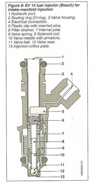
Notice how these use ball valves instead of the heavier pintle valves in the old EV1 style (Bosch 1680). Below are plots of driver signal, injector solenoid current, injector valve lift, and injector flow, which is mass flow I believe. Btw, Bosch flow tests and rates their injectors using n-heptane

When you have the ON signal from the injector driver (assumed to be standard, not peak-and-hold) you begin the ton phase. In ton you have the deadtime (where valve lift is zero) and a nonlinear flow portion where the valve is opening. Then you have peak valve lift period where flow is linear. Finally there is the toff phase where the injector signal is off but the injector is still delivering fuel as the valve closes.
Rotary Freak
Joined: Dec 2001
Posts: 2,402
Likes: 0
From: chandler, AZ
We are taking into account the non-linear portion of ton and toff when we measure deadtime and that is how the ecu compensates for them. This is exactly why deadtime cannot be measured with an oscilloscope.
Right, I think I get that part about calculating maximum pulsewidth for a given RPM. But, what I'm asking is basically if we took the ID graph at 100Hz scale, could we overlay it on a 160Hz scale identically in regards to flow rate (to represent a sequentially fired rotary with a maximum RPM of 10,000), but with the maximum horizontal unit being ~6Ms instead of 10Ms? Would the only thing that differ be the maximum controlled duty cycle due to having a fixed time required inbetween cycles to "recharge" the injector, or would the absolute flow rate be ~40% lower?
I'm not sure that I'm wording my question right...
I'm not sure that I'm wording my question right...
The answer to your question is,
As rpm goes up, available time for LINEAR (or approximately linear!) injection goes down. You stated you have more injections to do, with the same opening and closing time (you called it recharge which is fine).
To have linear injection, you will typically always have to budget at least 1mS for each squirt of non linear flow. Even 'linear' injectors such as IDs will still have some degree of non-linearity.
Look at the other plot ID supply of RPM vs. maximum linear injection rpm for a given injection strategy. The thing stopping linearness is the opening time.
Arrogant Wankeler
Joined: Nov 2006
Posts: 1,012
Likes: 233
From: Hunter Valley NSW Australia
I really do think it is pointless most of you going beyond a basic dead time vs voltage compensation and assumed linear flow beyond that given very few people will be using fully mapped load vs rpm rotor to rotor fuel trim with twin (high accuracy) widebands and any other tuning parafinalia, you simply don't have the means to even record the effects accurately, let alone balance all of the mapping with the ecus most are using.
Hopefully Howard makes some more progress without setback (feeling your pain in my work environment at the moment, can't catch a break, but plenty of breakages ) to stop all this off topic clowning.
Hopefully Howard makes some more progress without setback (feeling your pain in my work environment at the moment, can't catch a break, but plenty of breakages
) to stop all this off topic clowning.
I'm not sure why any of this fuel stuff is relevant. In using this information you are splitting hairs on an estimation that is based on several immeasurable (easily) assumptions. Why not just use the standard simplified equations for component sizing and rough set up, and then tune based on feedback. You still have to tune fuel quantity and timing manually anyway to account for all the variables not included in your estimation, and tuning from 90% is not much harder than tuning from 99%, whereas a 99% estimation is an order of magnitude more involved than a 90% one.
Even if you are not satisfied with the accuracy of tune you can get with logged EGT and AFR data, it would still be easier and more accurate to install cylinder pressure transducers and log the data than it is to try to effectively calculate the factors for injector latency and everything else and include it in your tune.
Even if you are not satisfied with the accuracy of tune you can get with logged EGT and AFR data, it would still be easier and more accurate to install cylinder pressure transducers and log the data than it is to try to effectively calculate the factors for injector latency and everything else and include it in your tune.


Thread Starter
Joined: Oct 2001
Posts: 6,279
Likes: 728
From: Florence, Alabama
just received a pic of the elbow w the injectors in place.
they are picking up two 90 degree fittings for the lines and we will be operative.

i will be able to use the shorty or standard length EV14s by just changing the two bolts.
howard
they are picking up two 90 degree fittings for the lines and we will be operative.

i will be able to use the shorty or standard length EV14s by just changing the two bolts.
howard


How will you pressurize these injectors? Are you planing on using a fuel pump and FPR? I would think that the 200psi pump a meth kits comes with cannot be regulated low enough to run fuel injectors or having the meth pump constantly running for pressure will burn it up?
Thread Starter
Joined: Oct 2001
Posts: 6,279
Likes: 728
From: Florence, Alabama
"where do you get injector holders like that?"
check w Luke Stubbs at Beyond Redline. i don't know how much of them was made from scratch. Luke handled the elbow part of the project.
"How will you pressurize these injectors? Are you planing on using a fuel pump and FPR? I would think that the 200psi pump a meth kits comes with cannot be regulated low enough to run fuel injectors or having the meth pump constantly running for pressure will burn it up?"
much of my new system is similar to my old FJO setup.
here's what i run:
4.5 gallon meth Jaz fuel cell located in my spare tire well. braided stainless line goes to a Bosch 044 variant external fuel pump located on my subframe. braided line out of the fuel pump under the driver's side half shaft to a Weldon meth adjustable fuel pressure regulator located under the nice black plastic protective shield just in front of the driver's side half shaft. thru a filter and a line that replaces the OE charcoal breather line up to the motor.
i do have a braided stainless return line from the regulator to the tank.
i also have an 8 foot section of SS brakeline that transports MAP to the regulator so i have constant net of boost pressure to the meth injectors.
i have a Honeywell boost switch in the engine compartment that i have adjusted to trigger the pump at 1.5 psi turbo boost.
in addition i have a pressure sensor in the meth line and i will be datalogging meth pressure so i will know what is going on at 8000 rpm. as well as knowing the pump is turning on properly etc.
i do plan to run as much pressure as i can thru my 1000 CC meth injectors as their ontime will be the same as my two other (secondary) gasoline injectors.
EV14s can run 8 bar pressure which is 116 psi. the max boost i plan to run is 30. so 116- 30 means i will set the injectors at 86 psi. i believe that will give me about another 40% deliverability.
i will be running the two EV14 1000 CC meth injectors and the 2 EV14 1000 CC gas secondary injectors wired in parallel and they will be controlled thru an FJO Peak and Hold converter module to destress the Power FC. ( i don't know that the Power FC won't be perfectly capable of running another set of injectors but the unit will lighten the load.)
i did receive my elbow today and probably will be able to fire it up tomorrow and dyno next week....
of course that only puts me about 10 months behind schedule.
hc
Rotary Freak
Joined: Dec 2001
Posts: 2,402
Likes: 0
From: chandler, AZ
8 bar is differential pressure across the injector. Since you're running an fpr, that means you can run 116psi base pressure and achieve even higher fuel flow.
Thread Starter
Joined: Oct 2001
Posts: 6,279
Likes: 728
From: Florence, Alabama
thanks for that Aaron, looks like a 63% flow increase rather than 40...
2000 CC, at 75% duty would be 1500 X 1.63 or 2445.
2000 CC, at 75% duty would be 1500 X 1.63 or 2445.
Last edited by Howard Coleman; Sep 16, 2011 at 12:13 PM.