GT35R Here I come! :D
 09-25-06, 09:05 AM
#151
Rotary Enthusiast
Thread Starter

Originally Posted by dubulup
PAINT BLACK!! please paint it black...

I thought it looks good silver, and it's stainless so it won't rust... I'll spray a test piece and see what it looks like.
 09-25-06, 10:00 AM
#152
development
okay sorry to be your, "GT35R Here I come!" show critic...but this is really all I see when I see see silver

well, of course your screen is way more classy...and robust.
black is just a little more stealthish
maybe test one of the oil cooler ducts...
well, of course your screen is way more classy...and robust.
black is just a little more stealthish
maybe test one of the oil cooler ducts...
09-25-06, 10:42 AM
#153
Rotary Enthusiast
Thread Starter
Originally Posted by dubulup
maybe test one of the oil cooler ducts...

Last edited by atihun; 09-25-06 at 10:49 AM.
 09-25-06, 01:22 PM
#155
Rotary Enthusiast
Thread Starter
I will eventually run one of our vented hoods, but even without one it still better than the stock setup or a front mount.
With a stock setup or front mount the air is going into the engine bay. At least with a v-mount setup, both IC and radiator get cold air, instead of first passing through the IC then to the radiator. Plus the radiator has the fans pointing downwards so the hot air will be directed to the underside of the car instead of the engine bay.
I won't know for sure until I drive the car, but I'm confident it will work.
Last edited by atihun; 09-25-06 at 01:24 PM.
09-25-06, 04:44 PM
#156
Rotary Enthusiast
Join Date: Jan 2002
Location: 15143
Posts: 859
Likes: 0
Received 0 Likes
on
0 Posts
Originally Posted by atihun
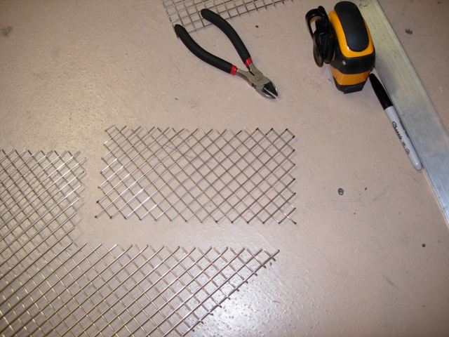
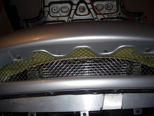
McMaster Carr is the shiznit! I found some welded stainless mesh that works great for the front bumper.
09-25-06, 05:16 PM
#157
Rotary Enthusiast
Thread Starter
http://www.mcmaster.com/nav/enter.as...12&pagenum=361
It's 9322T12.
I'll take a pic of the backside, but it was just a matter of cutting at a diagonal a piece that was 8.5 inches by 35 inches.
Then I just cut the ends to flap, put it between two pieces of straight aluminum along the lines I marked and put that in a vice and bent it along the lines.
It's 9322T12.
I'll take a pic of the backside, but it was just a matter of cutting at a diagonal a piece that was 8.5 inches by 35 inches.
Then I just cut the ends to flap, put it between two pieces of straight aluminum along the lines I marked and put that in a vice and bent it along the lines.
09-25-06, 06:33 PM
#158
I love it when someone sets a new standard. The bar keeps getting higehr and higher. My hat's off to you sir.
2 opinions if'n I may be so bold:
1) paint the mesh satin black. Use Bulldog adhesion proimotor and a flexible satin black bumper/plastic paint. It's less likely to chip, and
2) let the oil t-stat float. Use at most some *eek* zip ties. Even the slightest flex between engine and t'stat will either fatigue the fitting or work the threads loose over time. Even with solid motor mounts there will be movement between the front steering rack bracket you made and the engine front cover. The other option is simply to remove the t'stat altogther if you live in a warmer southern clime. Just takes a few more minutes to warm up is all
Keep it up and I'm just sad I'll probably never get to see the car in person.
Regards,
Crispy
09-26-06, 09:50 PM
#160
Senior Member
iTrader: (2)
Join Date: Apr 2006
Location: Austin, TX
Posts: 355
Likes: 0
Received 0 Likes
on
0 Posts
Noooo! I just read all 11 pages of this thread and then it suddenly ended. It's like reading a book with the last chapter missing... Where's the end!!!
Heh, great work. I'm just pulling the engine out of my car with plans for a lot of work and now I've got all kinds of ideas floating in my head.
Heh, great work. I'm just pulling the engine out of my car with plans for a lot of work and now I've got all kinds of ideas floating in my head.
09-29-06, 04:44 PM
#161
Rotary Enthusiast
Thread Starter
Thanks everyone to the input and props!
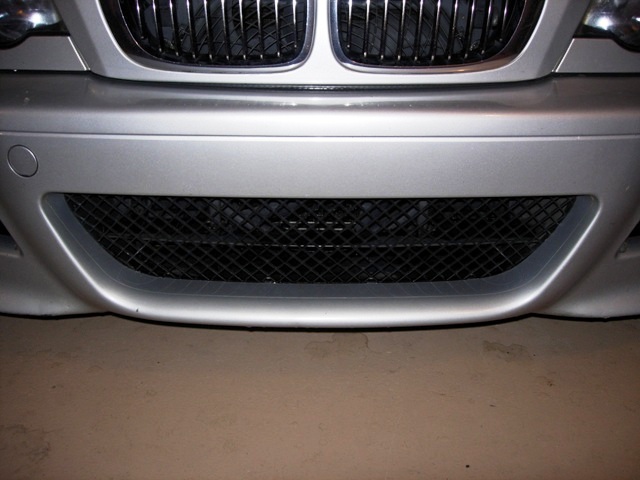
I ended up painting the mesh black, so we'll see what it looks like mounted this weekend.
(Crispy) The bracket I made for the oil t-stat is very flexible (it's 1/16 thin aluminum), almost like using zip ties. It's mounted so to move with the engine. I will probably end up making a bracket that holds it directly to the engine, or relocate it to the frame rail and make some lines with a little slack. I didn't think that running without a t-stat was an option; that might work also since it's normally warm here in SoCal.
Here's some pics of the mesh install as requested:
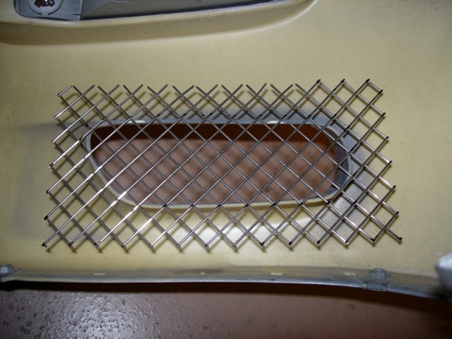
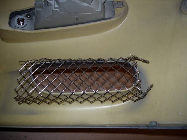
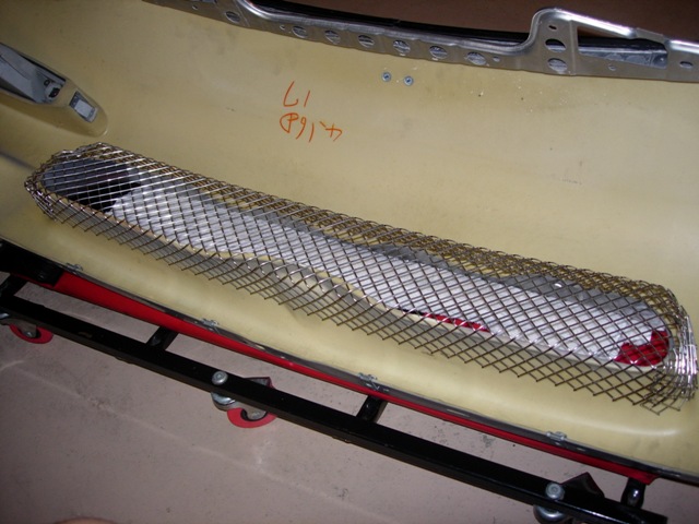
For the center grill, the way I cut and formed the mesh, I will use the 4 holes in the bumper support to mount it. The mesh will fit underneath the bumper skin and the bolts will go through and hold everything in place. As for the oil cooler mesh, well I haven't figured out how to mount them yet...
My wife says that I'm trying to copy her car; I told her it was the peer pressure!
I ended up painting the mesh black, so we'll see what it looks like mounted this weekend.
(Crispy) The bracket I made for the oil t-stat is very flexible (it's 1/16 thin aluminum), almost like using zip ties
. It's mounted so to move with the engine. I will probably end up making a bracket that holds it directly to the engine, or relocate it to the frame rail and make some lines with a little slack. I didn't think that running without a t-stat was an option; that might work also since it's normally warm here in SoCal.Here's some pics of the mesh install as requested:
For the center grill, the way I cut and formed the mesh, I will use the 4 holes in the bumper support to mount it. The mesh will fit underneath the bumper skin and the bolts will go through and hold everything in place. As for the oil cooler mesh, well I haven't figured out how to mount them yet...
My wife says that I'm trying to copy her car; I told her it was the peer pressure!
Last edited by atihun; 09-29-06 at 04:47 PM.
09-30-06, 05:43 AM
#162
Ghost Ride the Whip
It's the fitting between the thermostat and front cover. It broke on me twice! Spilled oil all over the track and had to get my car towed, pos. I just extended the oil cooler line from the front cover so that there is a line instead of just a fitting. IMO, the design was terrible. Just pay attention to see if there are any cracks or leaks coming from there. I'll try to get pics later
Originally Posted by atihun
Thanks for the heads up!
Is it the fitting between the thermostat and front cover, or the actual fitting on the thermostat?
I know that the fitment wasn't the best designed as the tstat is floating, so when I installed it, I made a bracket that is flexible and bolted it to the tstat bracket and the steering rack bolt. Since I have solid motor mounts, I think the bracket will help, maybe...
Can you post a pic of how you re-mounted yours?
10-05-06, 04:26 PM
#163
I think he is referring to the 90* fitting that comes from the cover to the thermostat.
It seems to me if it were solid, it would work stress and fail just from looking at it.
If you just replace the SOLID 90* fitting with a flexible joint (ie length of hose), there shouldn�t be any problem. Though it may not be as clean looking as the stock setup, durability comes first!
Looking good ! get those wheels on the ground and rolling and start enjoying your hard work
10-05-06, 05:46 PM
#164
7-Style
iTrader: (4)
Join Date: Apr 2004
Location: Lemoore, Ca
Posts: 750
Likes: 0
Received 0 Likes
on
0 Posts
Attilla,
Good m,eeting you last night. It looks even more impressive in person. just recieved my Koyo today so we'll get started on the cutting and welding. could you send me some detailed picts of the new placements.
Thanks,
Ken
Good m,eeting you last night. It looks even more impressive in person. just recieved my Koyo today so we'll get started on the cutting and welding. could you send me some detailed picts of the new placements.
Thanks,
Ken
10-13-06, 08:18 PM
#165
Ok, I have been following this thread for months now. I know numberous others have said "WOW" and I have to say the same. Your attention to detail and extreme patience with every small piece have me very impressed. I do not come close to possessing the patience that you do. This looks so clean... again....wow....
I am looking forward to hearing how break-in went as well as how it performs.
I am looking forward to hearing how break-in went as well as how it performs.
10-14-06, 04:38 PM
#166
Rotary Enthusiast
Thread Starter
Thanks guys...
I need some input.
Here's the vacuum/pressure routing that I'm doing:
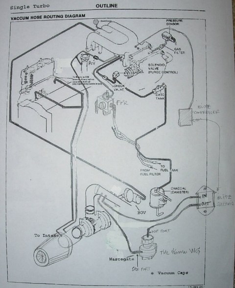
I would like some input on the following:
1. Wastegate... I didn't tap the turbo housing for a pressure port, but I do have two ports on the tubing that comes from the turbo outlet and I'm going to use them for the pressure lines needed for the wastegate and Blitz SBCID boost controller. Is it okay to have both seeing the same pressure?
2. I don't have room for an oil catch can. I do have two ports that are going into the tubing right after the intake filter. The oil injectors and oil filler tube will be connected like stock. Any issues doing this for the oil filler neck to avoid oil blowby and allow crankcase ventilation instead of using an oil catch can?
Thanks!
I need some input.
Here's the vacuum/pressure routing that I'm doing:
I would like some input on the following:
1. Wastegate... I didn't tap the turbo housing for a pressure port, but I do have two ports on the tubing that comes from the turbo outlet and I'm going to use them for the pressure lines needed for the wastegate and Blitz SBCID boost controller. Is it okay to have both seeing the same pressure?
2. I don't have room for an oil catch can. I do have two ports that are going into the tubing right after the intake filter. The oil injectors and oil filler tube will be connected like stock. Any issues doing this for the oil filler neck to avoid oil blowby and allow crankcase ventilation instead of using an oil catch can?
Thanks!
10-14-06, 08:01 PM
#167
Originally Posted by atihun
Thanks guys...
I need some input.
Here's the vacuum/pressure routing that I'm doing:
I would like some input on the following:
1. Wastegate... I didn't tap the turbo housing for a pressure port, but I do have two ports on the tubing that comes from the turbo outlet and I'm going to use them for the pressure lines needed for the wastegate and Blitz SBCID boost controller. Is it okay to have both seeing the same pressure?
2. I don't have room for an oil catch can. I do have two ports that are going into the tubing right after the intake filter. The oil injectors and oil filler tube will be connected like stock. Any issues doing this for the oil filler neck to avoid oil blowby and allow crankcase ventilation instead of using an oil catch can?
Thanks!
You know you're going to suck in heavy vapor (fuel/air with suspended oil) into the intake tract with/or without the catch can sucking back into the intake? There is room for a catch can...in front of the radiator.
10-16-06, 11:12 AM
#169
Rotary Enthusiast
Thread Starter
Thanks for the info. I will give it a try with the vacuum line to the intake first. I tee'd a really small line so that may just reduce the pressurization without pulling too much of the vapor / oil. We'll see.
I've finished pulling the battery cabling and the engine bay is 'ready'!
Here's the cabling run through the firewall (Battery and the Defi stuff). I found a nice grommet at McMaster that fits the large hole that was already there.
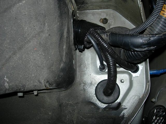
I was able to hold down the battery cable in the cabin so it doesn't rub / move around:
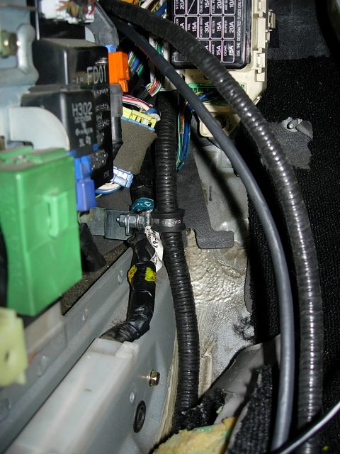
Here's the latest on the bay:
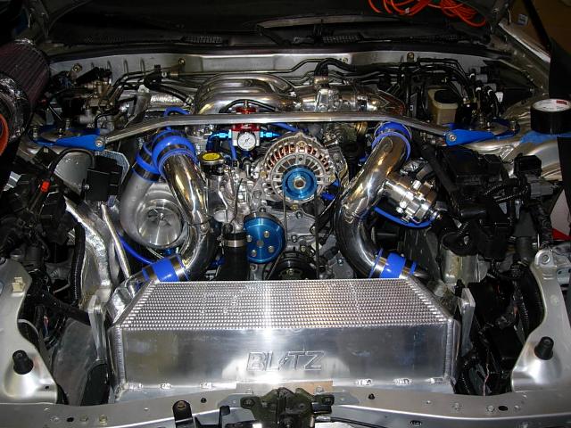
All I have to do now is a few minor things, mount and wire the battery, and wire up the WBO2 and other stuff, and I should be able to get into the PFC and configure everything to start it.
I've finished pulling the battery cabling and the engine bay is 'ready'!
Here's the cabling run through the firewall (Battery and the Defi stuff). I found a nice grommet at McMaster that fits the large hole that was already there.
I was able to hold down the battery cable in the cabin so it doesn't rub / move around:
Here's the latest on the bay:
All I have to do now is a few minor things, mount and wire the battery, and wire up the WBO2 and other stuff, and I should be able to get into the PFC and configure everything to start it.
10-16-06, 02:05 PM
#171
Originally Posted by atihun
Thanks guys...
I need some input.
Here's the vacuum/pressure routing that I'm doing:
I would like some input on the following:
1. Wastegate... I didn't tap the turbo housing for a pressure port, but I do have two ports on the tubing that comes from the turbo outlet and I'm going to use them for the pressure lines needed for the wastegate and Blitz SBCID boost controller. Is it okay to have both seeing the same pressure?
2. I don't have room for an oil catch can. I do have two ports that are going into the tubing right after the intake filter. The oil injectors and oil filler tube will be connected like stock. Any issues doing this for the oil filler neck to avoid oil blowby and allow crankcase ventilation instead of using an oil catch can?
Thanks!
I need some input.
Here's the vacuum/pressure routing that I'm doing:
I would like some input on the following:
1. Wastegate... I didn't tap the turbo housing for a pressure port, but I do have two ports on the tubing that comes from the turbo outlet and I'm going to use them for the pressure lines needed for the wastegate and Blitz SBCID boost controller. Is it okay to have both seeing the same pressure?
2. I don't have room for an oil catch can. I do have two ports that are going into the tubing right after the intake filter. The oil injectors and oil filler tube will be connected like stock. Any issues doing this for the oil filler neck to avoid oil blowby and allow crankcase ventilation instead of using an oil catch can?
Thanks!
http://www.negative-camber.org/crisp...glevachose.jpg
Regards,
Crispy
10-23-06, 09:30 AM
#173
Senior Member
iTrader: (2)
Join Date: Apr 2006
Location: Austin, TX
Posts: 355
Likes: 0
Received 0 Likes
on
0 Posts
Atilla,
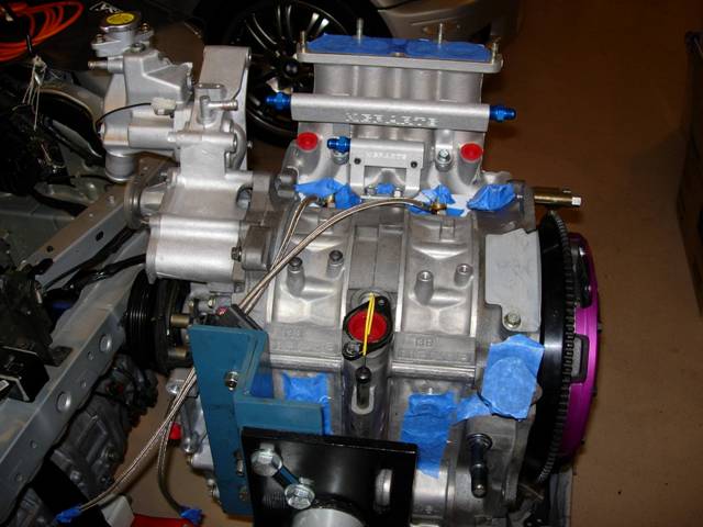
In the two pics I copied below, it looksl like you replaced your oil injector lines with stainless lines. Any chance I can get some more details on how you did that?
1. How did you connect the lines to the injectors?
2. How did you connect the lines at the other end?
3. Where did you get that little bracket that's holding the lines?
4. Where did you get the sleeves that are over the lines?
- Andy
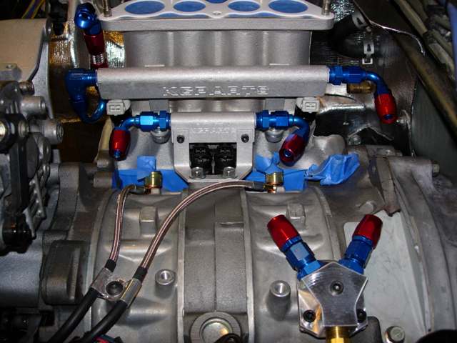
Originally Posted by atihun
...
10-23-06, 09:47 AM
#174
Original Gangster/Rotary!

iTrader: (213)
Originally Posted by palsor1
Atilla,
In the two pics I copied below, it looksl like you replaced your oil injector lines with stainless lines. Any chance I can get some more details on how you did that?
1. How did you connect the lines to the injectors?
2. How did you connect the lines at the other end?
3. Where did you get that little bracket that's holding the lines?
4. Where did you get the sleeves that are over the lines?
- Andy
here is one source for the lines:
http://www.gothamracing.com/catalog/...roducts_id=857
Looks like he fabbed the bracker himself, and those sleeves are most likely hose that he slit and held in place with zip ties.
10-23-06, 01:57 PM
#175
Rotary Enthusiast
Thread Starter
Originally Posted by GoodfellaFD3S
Hey Andy,
here is one source for the lines:
http://www.gothamracing.com/catalog/...roducts_id=857
Looks like he fabbed the bracker himself, and those sleeves are most likely hose that he slit and held in place with zip ties.
here is one source for the lines:
http://www.gothamracing.com/catalog/...roducts_id=857
Looks like he fabbed the bracker himself, and those sleeves are most likely hose that he slit and held in place with zip ties.
Yep, the bracket was just a piece of aluminum I bent up into a 'W' and used to mounting hole on top of the rotor housing.
As for the sleeves, they were actually Sumitomo Shrink tubes. I think they were 1/2 inch (barely made it over the fittings), and I used a micro torch to apply the heat necessary to shrink them onto the ss lines.
Once they shrink, they are about 1/16 thick, are tight against the ss line, and do not wear easily.