GT35R Here I come! :D

 06-03-06, 03:52 PM
#102
Original Gangster/Rotary!

iTrader: (213)
Originally Posted by ImranRX-7
Nice Attila! I need to get a harness soon too
Car is looking very sharp attila, nice job

 06-03-06, 05:22 PM
#104
Rotary Enthusiast
Thread Starter

Thanks guys!
It's one thing about custom stuff, you make one custom piece and then have to make four other ones because now the stock ones don't work...
The one I'm on right now is that since I've used the GZ oil pan and the LIM, the UIM sits further towards the front and higher up. I had to modify a bunch of crap including the strut tower bar.
Now I have to make a custom oil inlet pipe (the add oil tube) as the stock one is 1/4 too short .
.
It's one thing about custom stuff, you make one custom piece and then have to make four other ones because now the stock ones don't work...
The one I'm on right now is that since I've used the GZ oil pan and the LIM, the UIM sits further towards the front and higher up. I had to modify a bunch of crap including the strut tower bar.
Now I have to make a custom oil inlet pipe (the add oil tube) as the stock one is 1/4 too short
.
06-08-06, 04:13 PM
#106
Hey Attila, do you have any pics of just the modified WP housing?
I have been considering modifying mine, and am wondering exactly how you tackled the problem.
I planed to get �6 weld on fittings from jegs, but it looks like you accomplished adapting to AN by tapping and no welding?
Any pics or part numbers and descriptions of how you went about this?
I have been considering modifying mine, and am wondering exactly how you tackled the problem.
I planed to get �6 weld on fittings from jegs, but it looks like you accomplished adapting to AN by tapping and no welding?
Any pics or part numbers and descriptions of how you went about this?
06-08-06, 05:45 PM
#107
Originally Posted by rotarypower101
Hey Attila, do you have any pics of just the modified WP housing?
I have been considering modifying mine, and am wondering exactly how you tackled the problem.
I planed to get �6 weld on fittings from jegs, but it looks like you accomplished adapting to AN by tapping and no welding?
Any pics or part numbers and descriptions of how you went about this?
I have been considering modifying mine, and am wondering exactly how you tackled the problem.
I planed to get �6 weld on fittings from jegs, but it looks like you accomplished adapting to AN by tapping and no welding?
Any pics or part numbers and descriptions of how you went about this?
06-08-06, 08:59 PM
#108
Rotary Enthusiast
Thread Starter
Originally Posted by rotarypower101
Hey Attila, do you have any pics of just the modified WP housing?
I have been considering modifying mine, and am wondering exactly how you tackled the problem.
I planed to get �6 weld on fittings from jegs, but it looks like you accomplished adapting to AN by tapping and no welding?
Any pics or part numbers and descriptions of how you went about this?
I have been considering modifying mine, and am wondering exactly how you tackled the problem.
I planed to get �6 weld on fittings from jegs, but it looks like you accomplished adapting to AN by tapping and no welding?
Any pics or part numbers and descriptions of how you went about this?
 ).
).I messed up two housings in the process of learning. What I learned was that one of the nipples needs to be tapped smaller.
First you chop off the nipples all the way to the housing. Then you drill out the metal tube for the right size fittings and then tap it.
I was able to cut off the top nipple all the way to the housing and tap to a 3/8 to -6 fitting withouth any problems.
I cut off the lower nipple, but the housing thickness and hole is too small for a 3/8 npt fitting. I would put in the fitting and it would crack the lower piece (of crap!).
So I found a 1/4 to -6 fitting which worked perfect! Then once I put the fitting in place, I drilled out the center of the fitting to closely match the size of the -6 hole.
Last edited by atihun; 06-08-06 at 09:02 PM.
06-09-06, 01:18 AM
#109
Senior Member
Join Date: Nov 2001
Location: Malaysia
Posts: 567
Likes: 0
Received 0 Likes
on
0 Posts
Loving the setup you have. I'm undergoing a similar project and i must admit, i do come online and look at your pictures for reference. In fact i've printed a few and taken them to mechanic. He thinks you're GOD. LOL. Good luck. When do you plan to have the car running?
06-11-06, 11:34 AM
#110
Rotary Enthusiast
Thread Starter
Originally Posted by rotarypower101
Hey Attila, do you have any pics of just the modified WP housing?
...
Any pics or part numbers and descriptions of how you went about this?
...
Any pics or part numbers and descriptions of how you went about this?
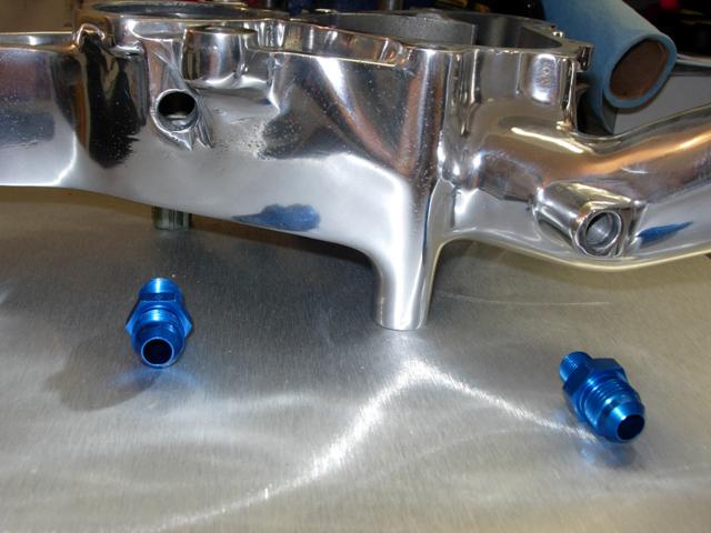
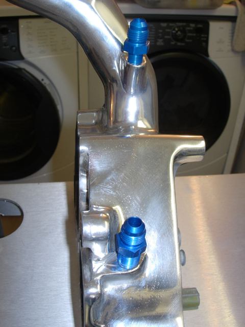
The first picture shows how I modified the housing. I cut the steel nipples all the way down to the housing. The top one has more material in the housing around the hole so using 3/8 NPT to -6 is okay.
The bottom one as you can see has very little wall material so when you drill and tap out the hole, the wall of the housing is very thin. That is where i used a 1/4 NPT to -6. Once in place I drilled out some of the fitting to make the hole larger.
One thing to note is that the nipples themselves are steel inserts, and you must make sure to drill them exactly on center to get all the material out and leave a good hole. On one of my housings on the small nipple, the steel insert was larger and therefore left a thin wall around the hole even after tapping it; that won't hurt unless it slides out.
Last edited by atihun; 06-11-06 at 11:46 AM.
06-11-06, 11:58 AM
#111
Rotary Enthusiast
Thread Starter
Originally Posted by fd3s7007
Loving the setup you have. I'm undergoing a similar project and i must admit, i do come online and look at your pictures for reference. In fact i've printed a few and taken them to mechanic. He thinks you're GOD. LOL. Good luck. When do you plan to have the car running?
I do the same thing when people post their pics and work! It's great when people share.
If I was "really" good, it wouldn't have taken me more than a year to get THIS far! At this poing when people as me when it will be running my answer is when it actually starts up
.
Last edited by atihun; 06-11-06 at 12:02 PM.
06-11-06, 01:35 PM
#112
Senior Member
Join Date: Nov 2001
Location: Malaysia
Posts: 567
Likes: 0
Received 0 Likes
on
0 Posts
Originally Posted by atihun
Thanks!
I do the same thing when people post their pics and work! It's great when people share.
If I was "really" good, it wouldn't have taken me more than a year to get THIS far! At this poing when people as me when it will be running my answer is when it actually starts up.
I do the same thing when people post their pics and work! It's great when people share.
If I was "really" good, it wouldn't have taken me more than a year to get THIS far! At this poing when people as me when it will be running my answer is when it actually starts up
.LOL.Its been 6 months for me. In the beginning the wife was very understanding but as i "laze" on she's been getting very pissed and has even hinted selling the rx if she's down again. i hope to actually get the car started latest by friday and put some miles on her before i tune.
what would be your break-in procedure? also, i just being **** here, in the picture above which one is the water inlet and outlet? sorry to sidetrack but i better get this right!! Thanks in advance mate.
dave
06-14-06, 04:42 PM
#113
Rotary Enthusiast
Thread Starter
For the break-in I will run a lighter weight non sythetic for about 1000 to 1500 miles at no boost and no high rpm runs. I'll tune all the non boost areas and driveability with the wideband.
I have an oil metering adapter that will feed from a reservoir some two stroke oil, so after 1500 miles I'll switch to synthetic in the engine. I'll switch from the stock plugs to NGK 9's and 10's. I'll slowly start going up in boost and rpm's and tune as needed.
Once I've got a good tune, I'll add in the water injection kit I have and make some adjustments.
Any input/suggestions are welcome!
BTW, here's some updates:
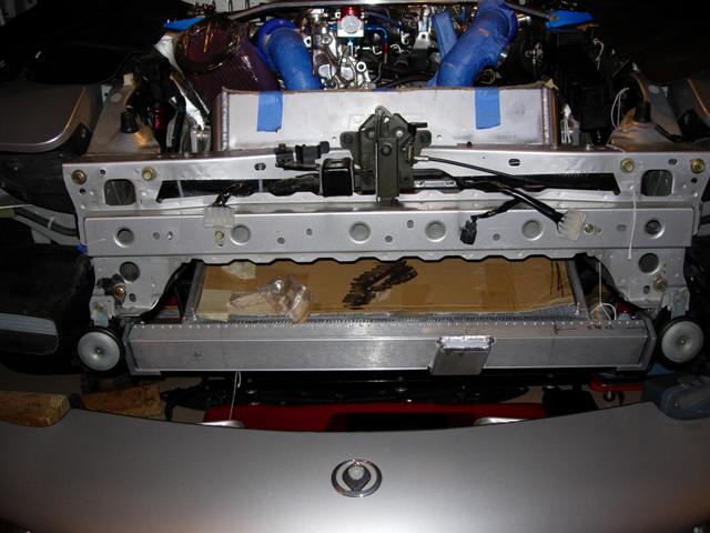
Here's the lower bracket for the radiator I made:
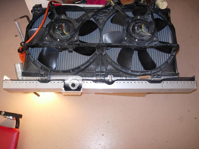
On the inlet side of the radiator I welded some aluminum angle pieces so I can easily mount a seperate duct for the radiator and the IC, effectively making a splitter between the two.
Here's the aluminum angle pieces welded onto the IC that will be used to hold the duct:
Another view:
Here's the tubing welded all up nicely:
So I have a little mig welder that's a 220 V 175A, and can weld aluminum up to 1/4 inch. It welds just fine on thicker things, but when I tried to weld up the 1/16 thick tubing, I was just blowing holes and melting the tubing even at lower settings. So I took it and had it tig welded together by a pro...
I have an oil metering adapter that will feed from a reservoir some two stroke oil, so after 1500 miles I'll switch to synthetic in the engine. I'll switch from the stock plugs to NGK 9's and 10's. I'll slowly start going up in boost and rpm's and tune as needed.
Once I've got a good tune, I'll add in the water injection kit I have and make some adjustments.
Any input/suggestions are welcome!
BTW, here's some updates:
Here's the lower bracket for the radiator I made:
On the inlet side of the radiator I welded some aluminum angle pieces so I can easily mount a seperate duct for the radiator and the IC, effectively making a splitter between the two.
Here's the aluminum angle pieces welded onto the IC that will be used to hold the duct:
Another view:
Here's the tubing welded all up nicely:
So I have a little mig welder that's a 220 V 175A, and can weld aluminum up to 1/4 inch. It welds just fine on thicker things, but when I tried to weld up the 1/16 thick tubing, I was just blowing holes and melting the tubing even at lower settings. So I took it and had it tig welded together by a pro...
06-14-06, 05:18 PM
#114
Rotary Enthusiast
Thread Starter
Oh, and I believe that the bottom one is the inlet and the top is the outlet. I don't think it matters which side you hook up the lines on the turbo.
06-30-06, 11:05 PM
#115
Rotary Enthusiast
Thread Starter
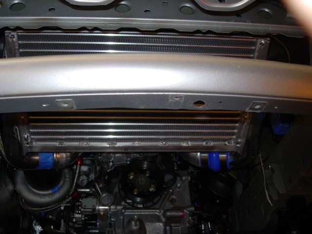
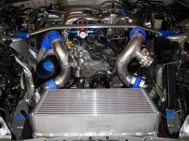
Alrighty, I've got a few updates !
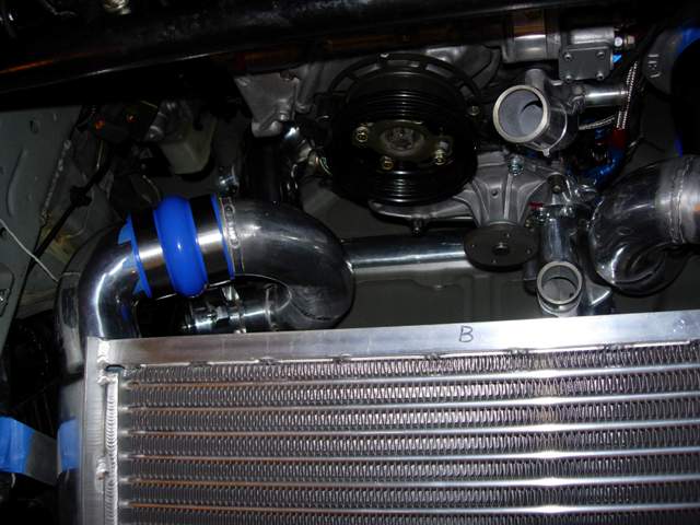
Here's the IC and radiator finally mounted. This **** ain't moving anywhere!
I found a great filter that's similar to the K&N but better weave and it has a velocity stack at the top. Plus it's big!
Here's the radiator bracket; I'm using a 1/8 inch thick rubber padding on the inside of the bracket all the way around the bottom of the radiator, so it's perfectly snug, no movement whatsoever!
Here's the bracket I made for mounting the Blitz FMIC. I bought a 3ft section of 4 x 6 x 3/8 90' angle aluminum and did "some" cutting. It doesn't move either...
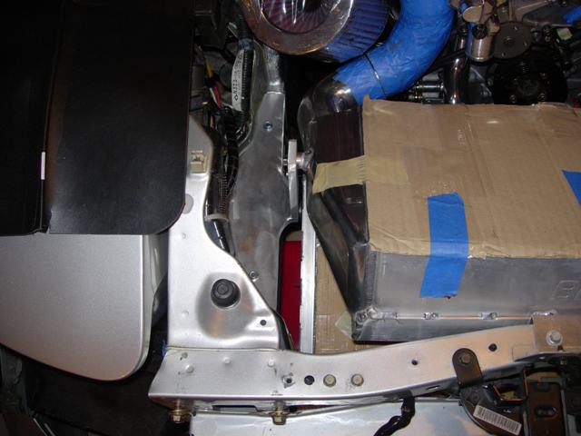
I'm working on the ducting and splitter. The way everything is mounted, I will have a nice space on both side for additional air to come into the engine bay, especially on the left side of the IC, right to the air filter.
It's getting there!
!Here's the IC and radiator finally mounted. This **** ain't moving anywhere!
I found a great filter that's similar to the K&N but better weave and it has a velocity stack at the top. Plus it's big!
Here's the radiator bracket; I'm using a 1/8 inch thick rubber padding on the inside of the bracket all the way around the bottom of the radiator, so it's perfectly snug, no movement whatsoever!
Here's the bracket I made for mounting the Blitz FMIC. I bought a 3ft section of 4 x 6 x 3/8 90' angle aluminum and did "some" cutting. It doesn't move either...
I'm working on the ducting and splitter. The way everything is mounted, I will have a nice space on both side for additional air to come into the engine bay, especially on the left side of the IC, right to the air filter.
It's getting there!
07-07-06, 11:52 AM
#122
Rotary Enthusiast
Thread Starter
Originally Posted by rotarypower101
What are the lower radiator brackets going to look like?
Thanks for the props!
Hopefully the pics will help others that want to do their own conversion. I was looking at a Apexi FMIC and it looks like that could be turned into a V-mount as well. I think most front mounts could be used.Yea, welding aluminum with a MIG is quite challenging to say the least. I can't do very thin pieces though (at least not nicely), that's why I had someone with a TIG do the IC piping and some additional radiator modifications.
07-10-06, 11:47 AM
#123
Rotary Enthusiast
Thread Starter
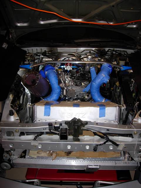
Yay, got the damn ducting finished! PITA, and I'm sure the neighbors love me for sawing and hammering early morning on Sunday!
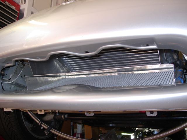
There's a nice space on each side that will allow air from the front to come into the engine bay. On the passanger side, I will make some additional ducting so it will direct air to the air filter.
There's a nice space on each side that will allow air from the front to come into the engine bay. On the passanger side, I will make some additional ducting so it will direct air to the air filter.
07-10-06, 01:37 PM
#124
Senior Member

Join Date: Nov 2004
Location: Fallston, MD
Posts: 627
Likes: 0
Received 0 Likes
on
0 Posts
Just curious, but why separate the two with that metal in between? If anything, you'd be blocking the path of air (albeit a tiny bit) and not allowing equalization between the rad and intercooler... in other words, say the intercooler is getting plenty of air, too much in fact, and the rad is maybe getting enough but could still flow more through it, without the separating piece the air would naturally be pushed through the rad where it would help, instead of getting pushed back out by the ducting, causing all kinds of turbulence and what-not.
Looks awesome, though!
Looks awesome, though!
07-10-06, 02:12 PM
#125
Rotary Enthusiast
Thread Starter
Originally Posted by rarson
Just curious, but why separate the two with that metal in between?
1. The radiator has much smaller fins than the intercooler and the the fins are much closer together on the radiator. Also, the radiator has much smaller spaces between each rib (where the coolant flows(radiator) or air flows(IC) inside). Due to these factors, the air would travel through the IC easier. The flow would not be equal between the two (path of least resistance).
2. The radiator has fans therefore even if it's getting less flow than the IC without the fans on, when you have the fans engage the flow will be more due to the pull. It would get less air if there was no splitter in place because it would be competing with the air being pushed through the IC core.
3. Without the splitter, there would be more turbulence because of the different flow rates of the radiator and IC cores and the different angles from horizontal. The way I have it setup is that once the air enters the ducted area it only has one way out which is through the core. The ducts are completely closed up.
We�ll see though!
Last edited by atihun; 07-10-06 at 02:17 PM.