Latest ExperimentģFailure!
 12-22-08, 06:58 AM
#201
"Elusive, not deceptive!ö
Thread Starter
Diabolical1
Check the picture on comment #186.
The rear housing appears to still be expanding at the plug bosses and lifting the apex seals as they cross that area. The seal looks like it teeter-totters across the leading plug bore
and maybe snaps on the cracked surface causing it to clean some of the surface carbon on the left hand side of the picture.
Mazda had an early problem with having owners run the engines too hard while still cold ( water temp below 50║C.) It cracked the spark plug boss and broke apex seals. Their fix was to sever the bosses as the Green Bros. have done.
My question is will this work on boosted engines? Or more to the point, boosted engines below 20 psi ?
Barry


 12-23-08, 07:59 PM
#203
Here are some photos to give you and idea of the direction I'm going later this week.
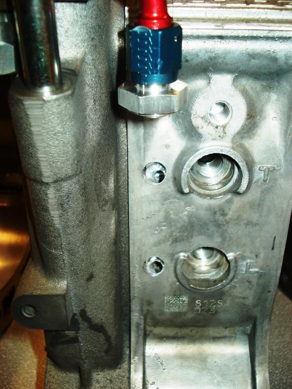
First two pictures are of the nozzles I was thinking of adding. The only issue I have with this setup is it could compromise the overall flow. Especially if I stick the nozzles out too far. For simplicity sake I'm leaning towards omitting the nozzles and letting the turbulent flow in that region do it's job in mixing the coolant to drop the overall coolant temps in that region.


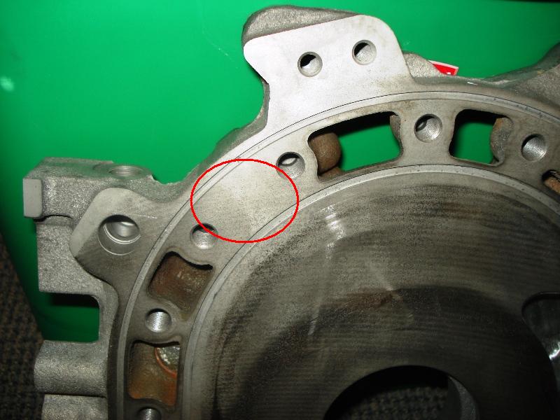
After looking at the coolant passages further today I noticed that one of the coolant ports on the rotor housings isn't even being utilized. And it's in a region where it needs it! So I will go further on the rotor housing slots and enlarged the bolt holes to make them into coolant passages in that region. It should help in prevent pre-ignition.


Another thing I will be doing is plugging the EGR port on the exhaust outlet. This opening just allows exhaust to be trapped on the center iron. No emission present, so no need for it.

First two pictures are of the nozzles I was thinking of adding. The only issue I have with this setup is it could compromise the overall flow. Especially if I stick the nozzles out too far. For simplicity sake I'm leaning towards omitting the nozzles and letting the turbulent flow in that region do it's job in mixing the coolant to drop the overall coolant temps in that region.
After looking at the coolant passages further today I noticed that one of the coolant ports on the rotor housings isn't even being utilized. And it's in a region where it needs it!
Another thing I will be doing is plugging the EGR port on the exhaust outlet. This opening just allows exhaust to be trapped on the center iron. No emission present, so no need for it.

 12-24-08, 07:36 AM
#206
"Elusive, not deceptive!ö
Thread Starter
Adam, I also block the exhaust holes leading to side housing intake ports.
But should we? Check out Yamamoto's data on housing temp balance.
Also note the center plate's cutaway for water, oil, and exhaust sections.
Your build is thought provoking as usual.
Barry
But should we? Check out Yamamoto's data on housing temp balance.
Also note the center plate's cutaway for water, oil, and exhaust sections.
Your build is thought provoking as usual.
Barry
12-24-08, 07:08 PM
#207
Barry,
To answer your question on blocking the EGR passage, in my opinion it's a compromise that I'm willing to take to prevent intake charge preheating. Also, if you look at Yamamoto's studies, they were primarily NA engine studies of air cooled/water cool motors. That begs the question if it's even valid in a turbo engine where EGR is ignored.
Update
External coolant line setup mods done, this hard line setup should address the leaks caused by the fittings of the old setup due to engine flex. Will have to run it and see.
12-25-08, 02:28 AM
#208
I have just been reading Jan P. Norbye's 1971 book The Wankel Engine that chronicles the development of the rotary engine from conception to production in 500+ pages addressing all the patent holders and their work.
After purchasing the patent rights in 1961, Toyo Kogyo (Mazda parent company) assigned 180 people rotary development and spent $750,000 to build and equip a special rotary engine testing facility with the latest technology of closed circuit camera systems to monitor, automatic data recording and computers.
The development they carried out is highly relevant today as the final Cosmo test engines were very similar to current production design.
One thing mentioned in the Toyo Kogyo section under cooling along with the schematics already posted was that Mazda blocked off some cooling passages to provide higher flow rates to the hot spots in the leading spark plug area.
If you are opening flow paths in the low heat areas as you indicated, make sure you compensate by upping flow in the high heat areas. For instance, providing a dedicated electric pump for your added cooling jets.
-----------------------------------------------------------------------------------------------------
Another thing to consider is the coolant you are using.
Even in Mazda's NA 110hp engines in a dyno cell with an constant supply of 90 deg C coolant the rotor housing temps were 200 deg C in the leading plug area at 7,000rpm.
Normal 70%/30% Ethylene Glycol and water at normal 15psi above atmospheric pressure (radiator cap pressure) boils at ~138 deg C. This means you have localized boiling at the leading plug area, or an area of vapor formation.
This vapor in contact with the housing surface has very, very low thermal conductivity (example, water vapor has ~36 times less thermal conductivity than water) so the surrounding coolant in fact is not being utilized effectively.
At zero above atmospheric pressure we have-
100% Ethylene Glycol = 197 C boiling, -13 C freezing, 16 mPa*s @25 C viscosity
100% Propylene Glycol = 188 C boiling, -59C freezing, 40 mPa*s @25 C viscosity
100% Evans NPG+ = 190.6 deg C, -40 C freezing, ~28 mPa*s @25 C viscosity
It turns out that even the much lower thermal conductivity of straight coolants (2 to 3 times less than water) below their boiling point is significantly better than the thermal conductivity of the vapor (36 times less) that is in contact with the housing with boiling water or coolant and water.
The rotary racers fix has been to use a straight coolant to raise the boiling point at the localized hot spot of the leading spark plug.
A bonus is the higher boiling point and viscosity will also help eliminate cavitation at the water pump.
Another bonus to those with a bridgeport and the interrupted coolant seal is that it will provide adequate cooling even with no pressure added above atmospheric and therefore reduce the chance of coolant leakage into the engine.
The favorite is Evans NPG+ as the proprietary mix of Glycols that try to lower viscosity, maximize thermal conductivity and maintain the low freezing point.
I have used Evans NPG+ and also much cheaper 100% Sierra coolant (Propylene Glycol). The PG though cheaper is much more viscous (more power draw), has lower thermal conductivity and will degrade in a couple of years.

 12-26-08, 01:50 AM
#212
Like this?


Oil mods-
-Oil pump pick up velocity stacked
-ported, polished oil pump cavities
-relocated oil cooler outlet
-loop line
-e-shaft thermal bypass eliminator
-Race e-shaft rotor oil jets
-Race oil pressure regulator
-relieved e-shaft oil galleys
-windowed, clearanced stat gear bearings
-ported/polished stat gear oil galleys
-largest FD rotor bearings
-RB pan baffle
12-26-08, 01:06 PM
#214
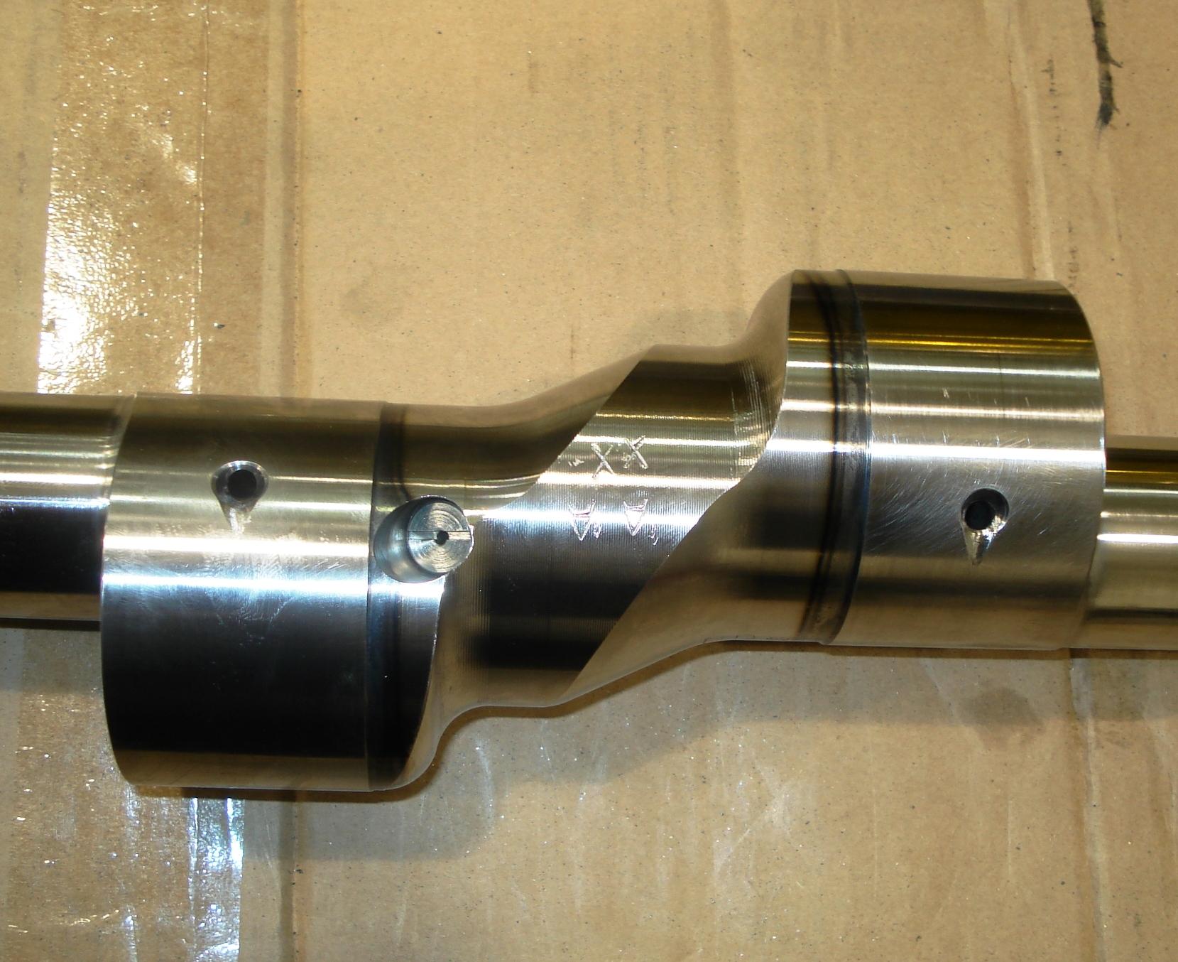
A few things, but I'd say mainly it's to help give a more direct flow of oil. Plus the fact that by having a teardrop shape, it causes a squish effect of the oil while the shaft rotates giving it a "higher" pressure which will better displace the oil across the bearing.
I've done the same thing on a few engines myself..... And don't see any issues with it.
-J
I've done the same thing on a few engines myself..... And don't see any issues with it.
-J
12-26-08, 03:45 PM
#215
Yeah reason I brought that up is because I sent my shaft off to get the same thing done. I can't remember who did it but it must be a big thing in the puerto rican rotary community I believe however when I asked kilo about it he just sorta laughed. lol. Oh well, to each their own I guess.
12-26-08, 04:54 PM
#216
Blue T2, did you drill a second oil passage on the eccentric shaft for the rear stationary bearing?
Since I have opened up all coolant passages to promote improved coolant flow as well utilizing mazmart water pump. The addition of the regions originally not getting coolant should only help. As far as localized boiling around the spark plugs, well water is best heat transfer material out there. Improving fluid velocity would be a course of action. I may go to a smaller wheel to increase flow. Need to find out the speed where cavitation occurs on the mazmart pump.
I was thinking of adding an external water pump for external cooling, but didn't like idea of the added complexity. Anyways if I go electric water pump might aswell run strictly on an electric pump.
Ive heard that warping is a side effect when using NRG coolant. Don't know if that's true though.
Last edited by afgmoto1978; 12-26-08 at 05:21 PM.
12-26-08, 10:50 PM
#217
Old [Sch|F]ool
What is the actual water pressure in the engine?
It should be higher than static pressure, given that there is a pump forcing coolant into the engine.
In SBCs it can reach 50psi under the right conditions.
It really would not be difficult to measure, just a 1/8NPT tap into the coolant passage of your choice.
It might actually be beneficial, if you could watch the instrument and see a pressure drop that should correspond to water pump cavitation.
I know with my old 12As, they would run hot if kept over 6000rpm for extended periods. I didn't make any kind of connection until I saw the RB catalog that had chart with cavitation speeds for various pump/pulley combinations. And so we learn.
Personally, I use just enough coolant to prevent freezing, plus a bottle of Water Wetter. Water conducts heat much better than coolant, and the water pump SHOULD provide enough pressure to prevent boiling.
Last edited by peejay; 12-26-08 at 10:54 PM.
12-27-08, 10:41 AM
#218
"Elusive, not deceptive!ö
Thread Starter
It turns out that even the much lower thermal conductivity of straight coolants (2 to 3 times less than water) below their boiling point is significantly better than the thermal conductivity of the vapor (36 times less) that is in contact with the housing with boiling water or coolant and water.
The rotary racers fix has been to use a straight coolant to raise the boiling point at the localized hot spot of the leading spark plug.
The rotary racers fix has been to use a straight coolant to raise the boiling point at the localized hot spot of the leading spark plug.
Adam and Peejay are correct, I think, by using as much plain water in the mix as possible and eliminating cavitation.
Peejay's idea of a 1/8" NPT fitting taking pressure readings looking for cavitation spiking is a very good one. The hole, if it were just beyond the sparkplug trench could later be used as a temp sensor location.
Adam, that tubular manifold feeding the rear housing hot spots looks really sharp.
Lots of great thoughts!
Barry
12-27-08, 03:25 PM
#219
Blue T2, did you drill a second oil passage on the eccentric shaft for the rear stationary bearing?
If you drill the rear journal without the loop line you would just aggravate the low oil pressure at the front eccentric shaft journal inlet.
Since I have opened up all coolant passages to promote improved coolant flow as well utilizing mazmart water pump. The addition of the regions originally not getting coolant should only help.
No, you have lowered coolant velocity in the hot region by opening the passages in the cool region.
Yes, the Mazmart pump will help flow over stock.
As far as localized boiling around the spark plugs, well water is best heat transfer material out there.
Adam and Peejay are correct, I think, by using as much plain water in the mix as possible
Put those properties together at the localized hot spot around the leading plug and you have transformation from fluid to vapor.
Vapor has a very low heat transfer rate.
Unfortunately, I believe you have no chance of normalizing this hot spot.
This is not a 4 stroke with a power stroke every 4th movement of the piston, this is not a 2 stoke with a power stroke every 2nd movement of the piston.
This is a phenomenon of the rotary engine with a power stroke every single movement of the rotary piston. The leading plug area is never swept by the cool unburned gasses of the compression stroke as it fires just as it is done being shrouded by contoured rotor face.
The use of nano particles of conductive metal in coolant to raise the thermal conductivity is a very interesting new field for me. You could have superior thermal conduction and high vaporization temperature.
12-27-08, 11:28 PM
#220
What? Come again on that last sentence?
Well opening up the coolant passages does reduce flow restriction. Which reduces overall pumping loses. Yes your right velocity at those small ports is reduced. But the overall flow velocity increases.
Well opening up the coolant passages does reduce flow restriction. Which reduces overall pumping loses. Yes your right velocity at those small ports is reduced. But the overall flow velocity increases.
12-28-08, 12:32 AM
#221
What? Come again on that last sentence?
Though 3% solution of copper nano particles only increased water's thermal conductivity 15% it increased Ethylene Glycol's by 40%!
These nano particles can of course be added to motor oil as well.
Well opening up the coolant passages does reduce flow restriction. Which reduces overall pumping loses. Yes your right velocity at those small ports is reduced. But the overall flow velocity increases.

will decrease flow in the hottest section of the engine (below trailing plugs to bottom center of engine).
12-28-08, 02:01 AM
#222
Your right that velocity is reduced with the addition of those passages, but the fact that in the original configuration those pockets of air make that region rather large sections of thermal insulation. And in a region where you really don't need increased surface temps in a high boost application or sustained high rpm's.
I maybe wrong, but if my tuning window is widened, then there something to my madness.
I maybe wrong, but if my tuning window is widened, then there something to my madness.
Last edited by afgmoto1978; 12-28-08 at 02:03 AM.
12-29-08, 01:26 AM
#224
Raising the pressure at the front bypass regulator with shims does not raise the pressure at the front stationary gear bearing.
All the oil goes from pump to front bypass to oil cooler to rear regulator to oil filter to rear stat gear bearing to upper dowels to front stat bearing. Rotor bearings and rotor cooling jets are fed by their respective stat gear bearings.
All the oil goes from pump to front bypass to oil cooler to rear regulator to oil filter to rear stat gear bearing to upper dowels to front stat bearing. Rotor bearings and rotor cooling jets are fed by their respective stat gear bearings.
12-29-08, 07:32 AM
#225
"Elusive, not deceptive!ö
Thread Starter
Barry
TII, Adam didn't mention the front regulator. He said front oil pressure. I had that first thought also.
Barry