
Haltech E6X Motonic trigger

Thread Starter
Senior Member
Joined: Jun 2004
Posts: 598
Likes: 0
From: SoCal
E6X Motonic trigger
does any body knows how to wire this thing up? I've got two pick up one leading and the other trailing, I wired the leading red and black to pin A and B but cant figure out where the trailing pickup lead goes to. Any body?
Joined: Feb 2001
Posts: 29,798
Likes: 128
From: London, Ontario, Canada
LOL. I just did this yesterday in a VW Corrado with a VR6 engine. The VW setup uses a 60-2 crank trigger (reluctor) and home trigger (Hall) on the crank. You're doing this on a 13B? Why? 
Thread Starter
Senior Member
Joined: Jun 2004
Posts: 598
Likes: 0
From: SoCal
Originally Posted by Aaron Cake
LOL. I just did this yesterday in a VW Corrado with a VR6 engine. The VW setup uses a 60-2 crank trigger (reluctor) and home trigger (Hall) on the crank. You're doing this on a 13B? Why?
That's how it was wired when i bought the set up. Will this work or do I have to go back to CAS?


You should still be able to set it up as a multi-tooth wheel. The stock CAS uses two pickups like you are describing. You have trigger and home wheels and pickups. The trigger wheel is the multi-tooth wheel and the home wheel should have one or two teeth. A motronic wheel uses only one sensor. It has multiple teeth with a missing tooth to trigger the home signal.
Assuming the pickups you have are reluctor type you need to supply them with a ground reference and the signal wire. Both the red and blue wires in the E6X trigger loom are grounds. Choose one of these, doesn't matter which, and supply one side of the reluctor with a ground. The yellow wire will go to the other side of the trigger pickup (the one reading the wheel with multiple teeth). The other pickup is wired with the other ground wire and the green home signal wire. In the trigger setup menu input the number of teeth on the trigger wheel. Set it for reluctor type trigger just like you would for a CAS.
If the sensors are Hall Effect sensors you'll need to supply them with ~5V+. You can source this from any of orange sensor supply wires. Once side of the pickup will receive 5V+ and the other side will be your signal wire. Again yellow for trigger and green for home. In the setup menu you'll still program it as multi-tooth but with Hall Effect selected along with the appropriate settings to go along with it.
Thread Starter
Senior Member
Joined: Jun 2004
Posts: 598
Likes: 0
From: SoCal
Originally Posted by C. Ludwig
You should still be able to set it up as a multi-tooth wheel. The stock CAS uses two pickups like you are describing. You have trigger and home wheels and pickups. The trigger wheel is the multi-tooth wheel and the home wheel should have one or two teeth. A motronic wheel uses only one sensor. It has multiple teeth with a missing tooth to trigger the home signal.
Assuming the pickups you have are reluctor type you need to supply them with a ground reference and the signal wire. Both the red and blue wires in the E6X trigger loom are grounds. Choose one of these, doesn't matter which, and supply one side of the reluctor with a ground. The yellow wire will go to the other side of the trigger pickup (the one reading the wheel with multiple teeth). The other pickup is wired with the other ground wire and the green home signal wire. In the trigger setup menu input the number of teeth on the trigger wheel. Set it for reluctor type trigger just like you would for a CAS.
If the sensors are Hall Effect sensors you'll need to supply them with ~5V+. You can source this from any of orange sensor supply wires. Once side of the pickup will receive 5V+ and the other side will be your signal wire. Again yellow for trigger and green for home. In the setup menu you'll still program it as multi-tooth but with Hall Effect selected along with the appropriate settings to go along with it.
Assuming the pickups you have are reluctor type you need to supply them with a ground reference and the signal wire. Both the red and blue wires in the E6X trigger loom are grounds. Choose one of these, doesn't matter which, and supply one side of the reluctor with a ground. The yellow wire will go to the other side of the trigger pickup (the one reading the wheel with multiple teeth). The other pickup is wired with the other ground wire and the green home signal wire. In the trigger setup menu input the number of teeth on the trigger wheel. Set it for reluctor type trigger just like you would for a CAS.
If the sensors are Hall Effect sensors you'll need to supply them with ~5V+. You can source this from any of orange sensor supply wires. Once side of the pickup will receive 5V+ and the other side will be your signal wire. Again yellow for trigger and green for home. In the setup menu you'll still program it as multi-tooth but with Hall Effect selected along with the appropriate settings to go along with it.
It is a reluctor type 2 wire red and black but I have two sensor not one. I re check the wiring and its wiresd like you said. black connected to negative (blue wire) and red connected to the trigger (yellow). So the other sensor will have to connected to the home signal and ground the red and green wire correct?
Trending Topics
Hey Ludwig, how do you set that up for rotary duty?
120 teeth
?? offset
Internal reluctor
?? gain
?? motronic filter
Distribuitor or Direct Fire?
etc... etc..
Will that fire the rotary correctly?
120 teeth
?? offset
Internal reluctor
?? gain
?? motronic filter
Distribuitor or Direct Fire?
etc... etc..
Will that fire the rotary correctly?
You'd set it up just like you would for the regular CAS. I am assuming he doesn't have a real motronic wheel. If he's using two sensors there has to be a dual wheel. Something similar to an FD setup...which is really quite similar to the CAS setup. Count the number of teeth on the trigger wheel and that would obviously be your tooth count. The home wheel should have only one tooth if it's crankfired (like the FD setup) or two teeth if it's running off the dizzy (like the CAS setup). If there are more teeth this guy is on his own.
For offset you'd have to play with it. Without the whole setup in front of me I couldn't offer advice.
All other settings would be just like a regualr CAS with a reluctor trigger. Adjust the gains to obtaina proper, clean signal. The point is that this isn't a motronic setup with a single wheel with a missing tooth. It's a dual trigger/dual wheel setup just like most stock RX-7 setups.
Thread Starter
Senior Member
Joined: Jun 2004
Posts: 598
Likes: 0
From: SoCal
Well this is a single wheel not a dual wheel like the one on the fd with two sensors. I'll have to count how many teeth there are and how many missing, but it may not matter cause it may never work.
I'm not quite sure how this set up ran before but it was taken out of a running sandrail until the owner decided to rebuilt the motor then ended up selling it. I spoke to haltech this morning and even their tech support was baffle on how this worked.
So I guess if this doesnt work then I'll have to go back to CAS and set it up that way. My only problem is that the front cover had been modified to take the oil fill hole where the distributor was, and the oil fill hole in the middle plate had been blocked off. Replacing the front cover is not a big deal I have front cover laying around to use, but it s the blocked oil fill hole that could be a problem.
Another thing that I want to do is pull the map off the computer and see what has been map out. But my stupid lap top crashed

'Tuna'
Joined: Feb 2001
Posts: 4,637
Likes: 3
From: Miami,Fl,USA
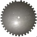
Now this **** just got difficult.! Looks like a 36-1
I was wondering Motronic wheel with two sensors on the same wheel on a rotary setup. I wonder if the Haltech E6-X is programmed to run a Rotary with that setup. I've seen it done but that was on a NA application firing lead and trail together.
Haltech's don't like Motronic on a rotary setup due to the 9k rpm limit of the unit. I have friends that tried it and had many problems at high rpm especialy with timing accuracy and rotary split timing on the trailing side.
Also most Motronic wheels use one sensor and use the missing tooth to determined TDC. I believe the early E6 and E6A series used the dual sensor setup on a motronic wheel but I might be wrong.
I've seen some Motronic setups with one sensor on the wheel(crank) and one on the cam(home) to do sequential injection but the ECU was programmed for that setup.
Looks like a 36-1I was wondering Motronic wheel with two sensors on the same wheel on a rotary setup. I wonder if the Haltech E6-X is programmed to run a Rotary with that setup. I've seen it done but that was on a NA application firing lead and trail together.
Haltech's don't like Motronic on a rotary setup due to the 9k rpm limit of the unit. I have friends that tried it and had many problems at high rpm especialy with timing accuracy and rotary split timing on the trailing side.
Also most Motronic wheels use one sensor and use the missing tooth to determined TDC. I believe the early E6 and E6A series used the dual sensor setup on a motronic wheel but I might be wrong.
I've seen some Motronic setups with one sensor on the wheel(crank) and one on the cam(home) to do sequential injection but the ECU was programmed for that setup.
Last edited by crispeed; Feb 13, 2006 at 05:51 PM.
Thread Starter
Senior Member
Joined: Jun 2004
Posts: 598
Likes: 0
From: SoCal
Yeah tell me about it, I hate to scrap this set up but then again I wont take any chances on it. I'll go ahead and replace the front cover and set up CAS just to be on the safe side.
I read that on the manual about the motronic not working above 9k, thats probablly why no one set it up for the rotary. Thanks for your input
I read that on the manual about the motronic not working above 9k, thats probablly why no one set it up for the rotary. Thanks for your input
Well, see, that's what i said. The wheel looks like its a 60-2, and when i saw the pics i went um, huh? o_0.
So, basically i think that the best course of action would be to just swap front covers and go with the tried and true setups we can ALL cooperate with you on.
So, basically i think that the best course of action would be to just swap front covers and go with the tried and true setups we can ALL cooperate with you on.
You should be able to set it up to run with that wheel. It ran at one time right? With that wheel you'll only need one sensor. The missing tooth is what triggers the home signal. When the Haltech is setup to read a motronic wheel it knows to look for the missing tooth. The question is what wheel is that exactly. Count the teeth. Download the Haltech manual and play with the software. Basically set the trigger up for motronic mode and input the number of teeth the wheel has. Offset will be varied in order to zero the timing.
The only thing the stock CAS or FD trigger systems are supplying the ECU with is engine speed and a home reference. The multi-tooth wheel of each stock trigger system feeds the ECU with engine speed and the single (FD) and twin (FC) wheels supply the home signal. The home signal is simply a signal to tell the ECU that the engine has completed a revolution and it's time to start all over again.
The motronic wheel is supplying the ECU with the same info. It counts the regularly spaced teeth to receive engine speed data and knows to look for the missing tooth. When the missing tooth passes the sensor the ECU sees it and knows that the engine has completed one revolution and it's time to start all over again. The motronic setup does all of this with one sensor. This is most likely the reason only one sensor was wired up when you started on this quest. That is what I get from your posts anyway. Correct?
Play with it. There is no reason to swap a bunch of stuff at this point. Anyone that took the time to set that system up probably knew a little bit about what they were doing. That trigger wheel install is slick and that mounting bracket for the triggers it damn nice!
The only caveat to all of that is the rpm limit as crispeed said.
Last edited by C. Ludwig; Feb 13, 2006 at 09:15 PM.
Oh, dont get me wrong, i by no means would back off on that trigger type, but since ive never done it and i am not infront of that engine working on that haltech, its kinda hard to offer any usefull help only on paper.
But i guess i would be able to make it work if i were there.
But i guess i would be able to make it work if i were there.
Thread Starter
Senior Member
Joined: Jun 2004
Posts: 598
Likes: 0
From: SoCal
Originally Posted by C. Ludwig
You should be able to set it up to run with that wheel. It ran at one time right? With that wheel you'll only need one sensor. The missing tooth is what triggers the home signal. When the Haltech is setup to read a motronic wheel it knows to look for the missing tooth. The question is what wheel is that exactly. Count the teeth. Download the Haltech manual and play with the software. Basically set the trigger up for motronic mode and input the number of teeth the wheel has. Offset will be varied in order to zero the timing.
The only thing the stock CAS or FD trigger systems are supplying the ECU with is engine speed and a home reference. The multi-tooth wheel of each stock trigger system feeds the ECU with engine speed and the single (FD) and twin (FC) wheels supply the home signal. The home signal is simply a signal to tell the ECU that the engine has completed a revolution and it's time to start all over again.
The motronic wheel is supplying the ECU with the same info. It counts the regularly spaced teeth to receive engine speed data and knows to look for the missing tooth. When the missing tooth passes the sensor the ECU sees it and knows that the engine has completed one revolution and it's time to start all over again. The motronic setup does all of this with one sensor. This is most likely the reason only one sensor was wired up when you started on this quest. That is what I get from your posts anyway. Correct?
Play with it. There is no reason to swap a bunch of stuff at this point. Anyone that took the time to set that system up probably knew a little bit about what they were doing. That trigger wheel install is slick and that mounting bracket for the triggers it damn nice!
The only caveat to all of that is the rpm limit as crispeed said.
The only thing the stock CAS or FD trigger systems are supplying the ECU with is engine speed and a home reference. The multi-tooth wheel of each stock trigger system feeds the ECU with engine speed and the single (FD) and twin (FC) wheels supply the home signal. The home signal is simply a signal to tell the ECU that the engine has completed a revolution and it's time to start all over again.
The motronic wheel is supplying the ECU with the same info. It counts the regularly spaced teeth to receive engine speed data and knows to look for the missing tooth. When the missing tooth passes the sensor the ECU sees it and knows that the engine has completed one revolution and it's time to start all over again. The motronic setup does all of this with one sensor. This is most likely the reason only one sensor was wired up when you started on this quest. That is what I get from your posts anyway. Correct?
Play with it. There is no reason to swap a bunch of stuff at this point. Anyone that took the time to set that system up probably knew a little bit about what they were doing. That trigger wheel install is slick and that mounting bracket for the triggers it damn nice!
The only caveat to all of that is the rpm limit as crispeed said.
Yeah it did run with that set up, the only reason why I had ask is one sensor is not wired up and I had no idea were it goes to. I couldnt find any answer why there is that second sensor and why. If thats how its suppose to be wire then I'll go ahead and leave it.
Another reason why I'm not too quick to scrap this idea was becasue of this two pictures below. But will see once I finish wiring I'll leave it alone and see how it goes.
Thread Starter
Senior Member
Joined: Jun 2004
Posts: 598
Likes: 0
From: SoCal
Originally Posted by Claudio RX-7
Hey Islandsnow,
What about the guys that had this running? where are they? arent they of any help?
What about the guys that had this running? where are they? arent they of any help?
Yeah I tried that route cant get a hold of em. why do think I'm here asking all this stupid question.
Thread Starter
Senior Member
Joined: Jun 2004
Posts: 598
Likes: 0
From: SoCal
First I thought it was R&R Rotary that wired it up and program the ecu. I spoke to steve today and he said they are the one who rebuilt the motor but they did not wire the ecu he did say that this was a running set up.
Adding the oil fill back to the center iron shouldn't be a big deal. Looks like a freeze plug has been added. If that's all it is then pop that out and knock a fill neck back in the hole. The front cover is another story all together.
'Tuna'
Joined: Feb 2001
Posts: 4,637
Likes: 3
From: Miami,Fl,USA
The problem with Motronic and Haltechs is the lack of high rpm capability. It takes a lot from the chip to calculate the missing tooth and calculate the timing due to the high frequency of the number of teeth present on a Motornic wheel and thus why it's not reccomended for high rpm use. I know a lot of people that have tried it. Also depending on who and what material was used to make the wheel they suffer from getting magnetised very easily leading to serious timing errors. Material choice is very critical for motronic use. Actualy there are very few ecu's that can run Motronic at high rpms. I can name one very high end ECU that claimed they can run it in a high rpm application but in actaully after finding it out the hard way and discussing it with them to later find out that it cannot do it.
A lot of Fords run the 36-1 setup. Toyota runs a 36-2 on the present Lexus 2j's with VVTI and the Scion motors along with most of their 4cyl line up. Mazda has joined in with their version of the 36-tooth wheel on the RX-8 with the most complicated design of all!
A lot of Fords run the 36-1 setup. Toyota runs a 36-2 on the present Lexus 2j's with VVTI and the Scion motors along with most of their 4cyl line up. Mazda has joined in with their version of the 36-tooth wheel on the RX-8 with the most complicated design of all!
Last edited by crispeed; Feb 14, 2006 at 01:33 AM.
'Tuna'
Joined: Feb 2001
Posts: 4,637
Likes: 3
From: Miami,Fl,USA
Originally Posted by C. Ludwig
You should be able to set it up to run with that wheel. It ran at one time right? With that wheel you'll only need one sensor. The missing tooth is what triggers the home signal. When the Haltech is setup to read a motronic wheel it knows to look for the missing tooth. The question is what wheel is that exactly. Count the teeth. Download the Haltech manual and play with the software. Basically set the trigger up for motronic mode and input the number of teeth the wheel has. Offset will be varied in order to zero the timing.
The only thing the stock CAS or FD trigger systems are supplying the ECU with is engine speed and a home reference. The multi-tooth wheel of each stock trigger system feeds the ECU with engine speed and the single (FD) and twin (FC) wheels supply the home signal. The home signal is simply a signal to tell the ECU that the engine has completed a revolution and it's time to start all over again.
The motronic wheel is supplying the ECU with the same info. It counts the regularly spaced teeth to receive engine speed data and knows to look for the missing tooth. When the missing tooth passes the sensor the ECU sees it and knows that the engine has completed one revolution and it's time to start all over again. The motronic setup does all of this with one sensor. This is most likely the reason only one sensor was wired up when you started on this quest. That is what I get from your posts anyway. Correct?
Play with it. There is no reason to swap a bunch of stuff at this point. Anyone that took the time to set that system up probably knew a little bit about what they were doing. That trigger wheel install is slick and that mounting bracket for the triggers it damn nice!
The only caveat to all of that is the rpm limit as crispeed said.
The only thing the stock CAS or FD trigger systems are supplying the ECU with is engine speed and a home reference. The multi-tooth wheel of each stock trigger system feeds the ECU with engine speed and the single (FD) and twin (FC) wheels supply the home signal. The home signal is simply a signal to tell the ECU that the engine has completed a revolution and it's time to start all over again.
The motronic wheel is supplying the ECU with the same info. It counts the regularly spaced teeth to receive engine speed data and knows to look for the missing tooth. When the missing tooth passes the sensor the ECU sees it and knows that the engine has completed one revolution and it's time to start all over again. The motronic setup does all of this with one sensor. This is most likely the reason only one sensor was wired up when you started on this quest. That is what I get from your posts anyway. Correct?
Play with it. There is no reason to swap a bunch of stuff at this point. Anyone that took the time to set that system up probably knew a little bit about what they were doing. That trigger wheel install is slick and that mounting bracket for the triggers it damn nice!
The only caveat to all of that is the rpm limit as crispeed said.
So basically that is why manufacturers these days are using 36 tooth wheels instead of 60-2.
Makes a whole lot of sense, i hadnt counted the teeth on the RX-8 motors i thought it was 60, guess it makes more sense, since the rotary spins so high.
So, in short islandsnow, back to stock for you.
Makes a whole lot of sense, i hadnt counted the teeth on the RX-8 motors i thought it was 60, guess it makes more sense, since the rotary spins so high.
So, in short islandsnow, back to stock for you.

Thread
Thread Starter
Forum
Replies
Last Post
windom
Adaptronic Engine Mgmt - AUS
4
Sep 11, 2015 04:48 AM