
Custom Solenoid Rack


Thread Starter
Joined: Apr 2005
Posts: 2,488
Likes: 8
From: California, SF
Hah, awesome!
By the way, did you get a chance to read over the instruction and take a quick look at the vacuum diagram? Any concerns, advice will be gladly accepted as I am trying to improve every little thing I can to make this a better kit for all of us!~
Cheers,
Eric Zheng

By the way, did you get a chance to read over the instruction and take a quick look at the vacuum diagram? Any concerns, advice will be gladly accepted as I am trying to improve every little thing I can to make this a better kit for all of us!~
Cheers,
Eric Zheng

I took a look at the instructions and I am confused where you talk about an open metal vacuum line that one of the black caps goes on, but I took a look at my car and did not see what you are refering too. I do not have a open metal line in that location as you show! As your vacuum diagram shows it is adjacent to the vacuum tank hose connection.
Is that open metal vacuum line suppose to be open on a stock car, and if it is what is the purpose of it open to atmosphere? and know it needs to be capped, I am confused!!
Is that open metal vacuum line suppose to be open on a stock car, and if it is what is the purpose of it open to atmosphere? and know it needs to be capped, I am confused!!
Thread Starter
Joined: Apr 2005
Posts: 2,488
Likes: 8
From: California, SF
I took a look at the instructions and I am confused where you talk about an open metal vacuum line that one of the black caps goes on, but I took a look at my car and did not see what you are refering too. I do not have a open metal line in that location as you show! As your vacuum diagram shows it is adjacent to the vacuum tank hose connection.
Is that open metal vacuum line suppose to be open on a stock car, and if it is what is the purpose of it open to atmosphere? and know it needs to be capped, I am confused!!
Is that open metal vacuum line suppose to be open on a stock car, and if it is what is the purpose of it open to atmosphere? and know it needs to be capped, I am confused!!
Does that make sense?
Maybe I can elaborate a little more to clarify things as such. *Thanks for letting me know, let me clarify that.
-Eric
So what hose is connected to the nipple? Is it from the original TCV solenoid ? If it is why not just install the new hose from the new TCV solenoid and you would not have to install a tee fitting?
Thread Starter
Joined: Apr 2005
Posts: 2,488
Likes: 8
From: California, SF
Be creative, hence I gave you guys a diagram to follow the routing. If you see a need to remove some hoses or Tees to suit your need. Please do so and if you can explain the reason behind on this thread, it will be greatly appreciated as it can help us to make it more simplify if necessary.
Here I've attached another vacuum diagram with a 3 red circles. The one in the center is the nipple you're describing. The others are to show you that they are sharing the same vacuum source. Therefore I capped the center circle tubing, and have a hose on the right and made a Tee to share the vacuum source. Let me know if you have any more questions.
-Eric
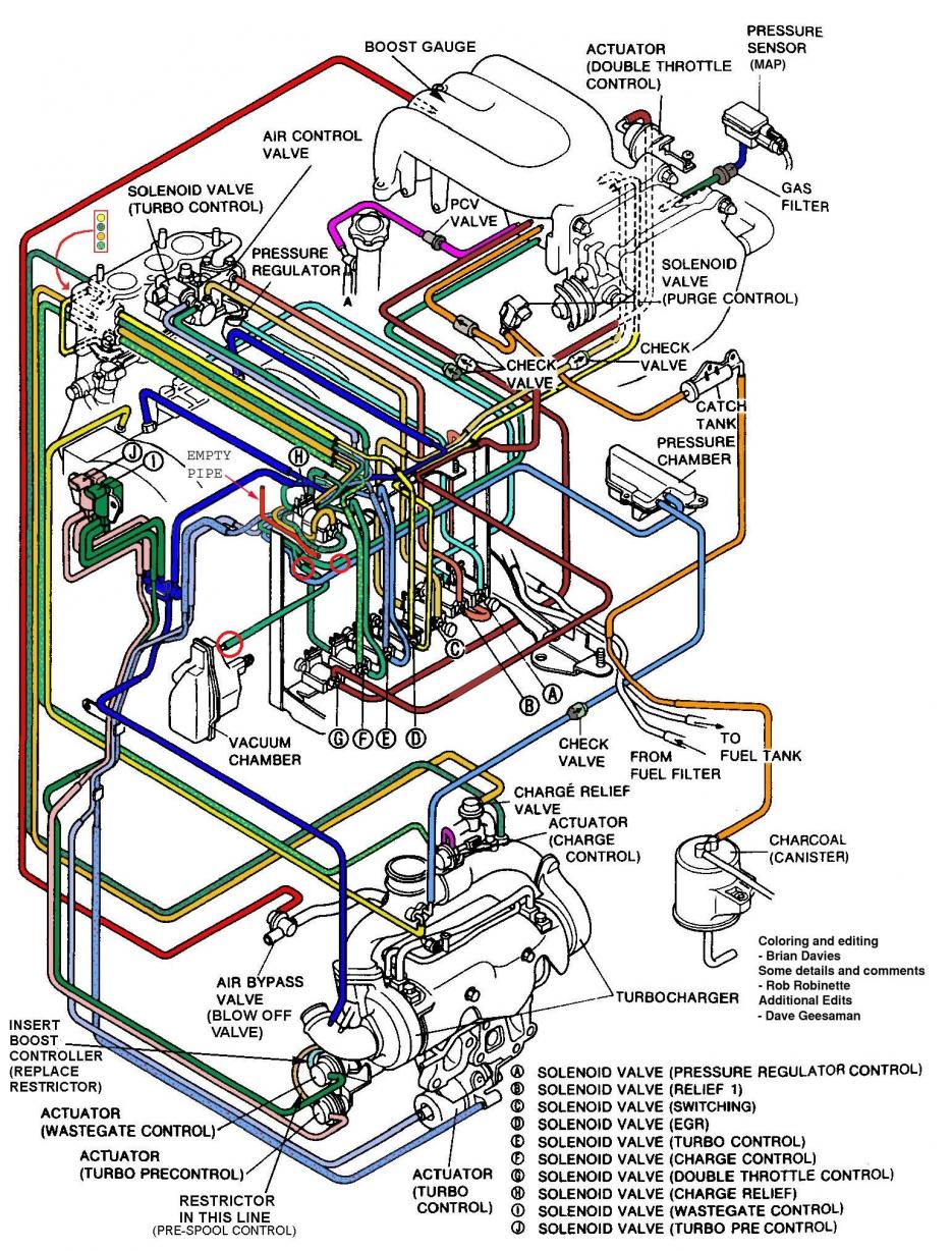
The picture in your instructions does not show the tee'd line tied into the vacuum chamber. How does the vacuum chamber tie into the metal tube were the tee'd hose with check valve connects?
Thread Starter
Joined: Apr 2005
Posts: 2,488
Likes: 8
From: California, SF
Thank you for noticing that. That's some good eyes you've got there! I apologize for any confusion this have caused. Let me look into this and get back to you asap! Thanks!
-Eric
Thread Starter
Joined: Apr 2005
Posts: 2,488
Likes: 8
From: California, SF
The hose was originally connected to the Pressure chamber which then connects to the TCV(stock oem pressure solenoid) as I verified it today. Therefore all you need to do was cap that nipple, since we replaced it with a new TCV(pressure) solenoid(E). The new TCV (pressure E solenoid) will be connected directly to the pressure chamber and the other orange hose will be routed to the Y-pipe (with the one-way check valve). That issue is currently being fixed on the wiring diagram.
To clarify that the Tee is necessary because it is on a the RED route in the diagram I've provided. Which is TCV(vacuum) not TCV(pressure).
If looked carefully in the diagram I've posted in the above, the LIGHT BLUE that connects to the pressure chamber is the metal tube I capped. And RIGHT UNDERNEATH the green hose is a Y-metal tubing connected originally routed into the UIM (vacuum). And according to the RED routing diagram I've provided, that's the best place to Tee into.
What you were looking into is the ORANGE route and we got confused because it is right next to the RED routing and we got that mixed up.
Is it more clear now? If not, I strongly suggest looking at the metal tubing in the car *it is visible without removing the UIM* that there is another metal tube for the vacuum chamber (right below the Tee'd vacuum hose)
Thank you for noticing that as I was confused myself due to these metal tubing are routed so closed to each other and cannot be seen in the pictures.
-Eric
Last edited by AzEKnightz; Nov 5, 2011 at 05:32 PM.
Yep Makes sense now! The capped metal tube was the pressure chamber connection and not vacuum. The vacuum chamber is already hooked to metal tube Y connection which ties to the metal tube which the hose and tee fitting you show in your picture.
E Solenoid is for pressure TCV-P and X Solenoid is for vacuum TCV-V
Thanks!
E Solenoid is for pressure TCV-P and X Solenoid is for vacuum TCV-V
Thanks!
Thread Starter
Joined: Apr 2005
Posts: 2,488
Likes: 8
From: California, SF
Yep Makes sense now! The capped metal tube was the pressure chamber connection and not vacuum. The vacuum chamber is already hooked to metal tube Y connection which ties to the metal tube which the hose and tee fitting you show in your picture.
E Solenoid is for pressure TCV-P and X Solenoid is for vacuum TCV-V
Thanks!
E Solenoid is for pressure TCV-P and X Solenoid is for vacuum TCV-V
Thanks!
Yea, it was pretty darn confusing without looking at the actual rat's nest. Anyways, glad we got that figured out!
-Eric


Thread Starter
Joined: Apr 2005
Posts: 2,488
Likes: 8
From: California, SF
Thread Starter
Joined: Apr 2005
Posts: 2,488
Likes: 8
From: California, SF
Mind taking some photos and instructions for those that might be interested? Or just photos should be plenty enough, no need to instructions since we all mechanically inclined haha!
cheers,
-Eric
Well to me mounting it near the abs seems a little out of place and since I'm running the stock intake box it will not be visible unless you remove the box and intake hoses.
The hard part is modifying the support bar to my liking and I think I can skip the hard vacuum lines labeled X and E since their target will be relatively close to where the solenoids are being mounted.
The unused hard lines can then be used to connect the line running to the vacuum chamber, though this is all just by looking at the diagrams. I will update you guys on how I proceed with the install when I get to it.
Thread Starter
Joined: Apr 2005
Posts: 2,488
Likes: 8
From: California, SF
Well to me mounting it near the abs seems a little out of place and since I'm running the stock intake box it will not be visible unless you remove the box and intake hoses.
The hard part is modifying the support bar to my liking and I think I can skip the hard vacuum lines labeled X and E since their target will be relatively close to where the solenoids are being mounted.
The unused hard lines can then be used to connect the line running to the vacuum chamber, though this is all just by looking at the diagrams. I will update you guys on how I proceed with the install when I get to it.
The hard part is modifying the support bar to my liking and I think I can skip the hard vacuum lines labeled X and E since their target will be relatively close to where the solenoids are being mounted.
The unused hard lines can then be used to connect the line running to the vacuum chamber, though this is all just by looking at the diagrams. I will update you guys on how I proceed with the install when I get to it.
-Eric

hey buddy.  Got my trackingnumber? Im tracking it, and it doesnt look too good
Your Item's StatusYour item was accepted at 3:02 pm on September 23, 2011 in ENFIELD, NC 27823. No further information is available for this item.

Got my trackingnumber? Im tracking it, and it doesnt look too good Your Item's StatusYour item was accepted at 3:02 pm on September 23, 2011 in ENFIELD, NC 27823. No further information is available for this item.
Thread Starter
Joined: Apr 2005
Posts: 2,488
Likes: 8
From: California, SF
Thanks for letting me know.
****UPDATES****
Parts for GB #2 just came in right now. I will have everything ready and ship out by Tuesday mid noon. Thanks all!
-Eric

Was it shipped via USPS? If so that's normal. USPS uses delivery confirmation, which isn't a tracking system. It only updates when the item is shipped, and when the item is delivered.
No stress buddy
My car is winter-parked for the year, so it wont see daylight for the next months and the package is a 10 day package, and its been close to 20 now.
Thread Starter
Joined: Apr 2005
Posts: 2,488
Likes: 8
From: California, SF
No stress buddy My car is winter-parked for the year, so it wont see daylight for the next months ....
.... I know, but it should read when it hits the norwegian border/customs, as they scan in the package then. I cant even find it on the norwegian mail site www.posten.no
and the package is a 10 day package, and its been close to 20 now.
My car is winter-parked for the year, so it wont see daylight for the next months ........ I know, but it should read when it hits the norwegian border/customs, as they scan in the package then. I cant even find it on the norwegian mail site www.posten.no
and the package is a 10 day package, and its been close to 20 now.
I agreed that it shouldve updated the system, and on top of that, i shipped it out on October, not September. Therefore something is weird or mistaken.
-Eric
