
Big Turbo Time! Midsummer 2007 Pics/Update On Project Tina

Thread Starter
Joined: Feb 2001
Posts: 29,798
Likes: 128
From: London, Ontario, Canada
Big Turbo Time! Midsummer 2007 Pics/Update On Project Tina
It's that time again. Yes, time for another update on my ongoing (but nearly complete!) turbo-NA bridgeport project. Of course, after the last thread, it should now be known as the "big turbo-NA bridgeport project". As the last thread primarily dealt with fabricating an exhaust manifold to mount up the GT4088R, it's well into the big turbo category now.
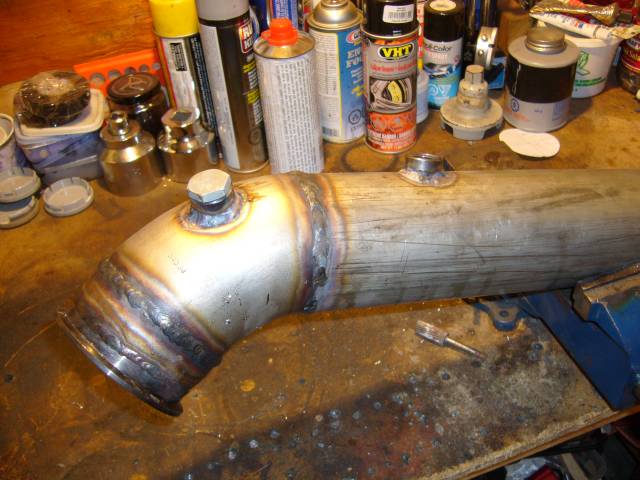
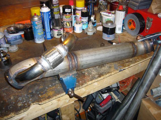
We left off last time after finish welding the turbo outlet pipe. Welding rod was used to form a lip to prevent the coupler from blowing off. This was some tricky welding at very lower current levels.
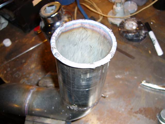
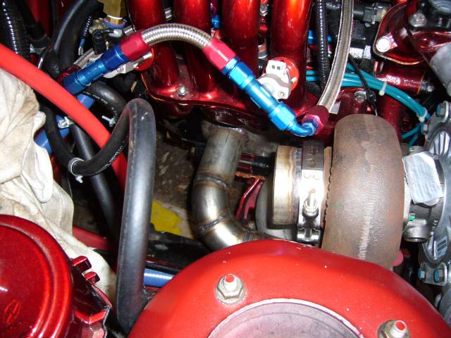
Now that the outlet pipe was complete, the downpipe was the next task. Here's the first section welded onto the 3" V-band and clamped to the turbo. This section allows the V-band flange to match up with the 3" SCH 10 pipe used to make the downpipe. Yes, I said SCH10 pipe. Now before everyone yells "Pipe! It's so thick and heavy. Ghetto! Fail! FTL!" I should mention that while it is a bit heavier then most aftermarket downpipes, it's not nearly as heavy as you would think. We'll get to the exact weight later and I'll point out why I chose to use SCH 10 pipe instead of the more commonly used tube...
From the reducer I used a 45 degree el to angle the pipe down, then tacked on a straight section to bring the pipe level with the bottom of the engine.
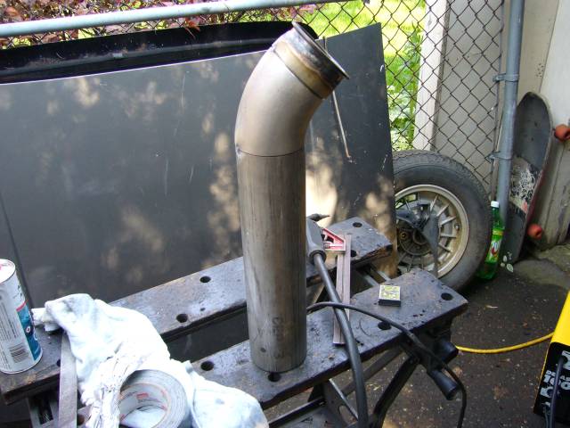
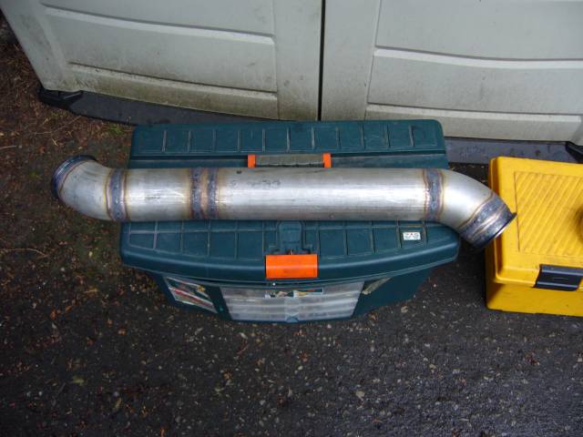
I skipped ahead a little with the pictures as I've covered pipe making before a few times. Here's the downpipe on the bench and ready to weld.
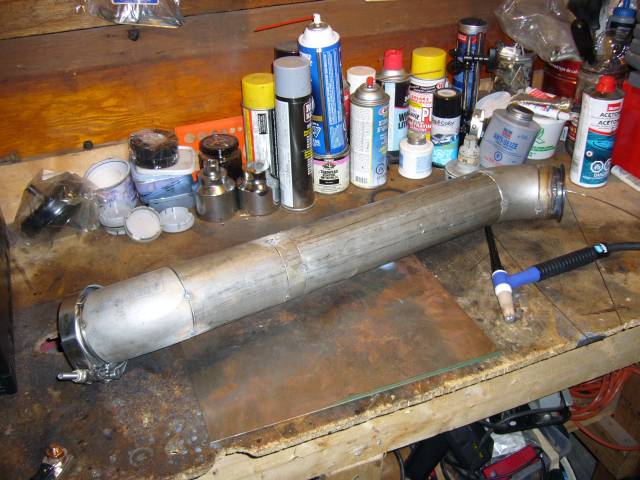
After about half an hour behind the TIG torch, the downpipe was fully welded.
The main reason I made the downpipe out of SCH 10 pipe is because of noise and heat. My ears are a bit sensitive to high pitched noises and on nearly every rotary exhaust I've heard, the pinging and ringing noises drive me crazy. Cars should not sound like marbles in a tin can. Thick pipe makes an enormous difference in the sound you hear from the engine bay which is one reason that OEM downpipes are nearly always thick castings. The thicker pipe also tends to keep heat inside the pipe where it belongs instead of allowing it to easily travel through thin walls. With a little heat wrap, I expect to be able to place my hand on the downpipe while the engine is running. As for weight, this pipe ended up at 11 LBs which is far from "heavy". Quite a bit lighter then the stock precat, but not as light as some aftermarket (though noisy) downpipes. 3" SCH 10 pipe also has a 3.25" inner diameter so I pick up a little flow over tube as well.
We left off last time after finish welding the turbo outlet pipe. Welding rod was used to form a lip to prevent the coupler from blowing off. This was some tricky welding at very lower current levels.
Now that the outlet pipe was complete, the downpipe was the next task. Here's the first section welded onto the 3" V-band and clamped to the turbo. This section allows the V-band flange to match up with the 3" SCH 10 pipe used to make the downpipe. Yes, I said SCH10 pipe. Now before everyone yells "Pipe! It's so thick and heavy. Ghetto! Fail! FTL!" I should mention that while it is a bit heavier then most aftermarket downpipes, it's not nearly as heavy as you would think. We'll get to the exact weight later and I'll point out why I chose to use SCH 10 pipe instead of the more commonly used tube...
From the reducer I used a 45 degree el to angle the pipe down, then tacked on a straight section to bring the pipe level with the bottom of the engine.
I skipped ahead a little with the pictures as I've covered pipe making before a few times. Here's the downpipe on the bench and ready to weld.
After about half an hour behind the TIG torch, the downpipe was fully welded.
The main reason I made the downpipe out of SCH 10 pipe is because of noise and heat. My ears are a bit sensitive to high pitched noises and on nearly every rotary exhaust I've heard, the pinging and ringing noises drive me crazy. Cars should not sound like marbles in a tin can. Thick pipe makes an enormous difference in the sound you hear from the engine bay which is one reason that OEM downpipes are nearly always thick castings. The thicker pipe also tends to keep heat inside the pipe where it belongs instead of allowing it to easily travel through thin walls. With a little heat wrap, I expect to be able to place my hand on the downpipe while the engine is running. As for weight, this pipe ended up at 11 LBs which is far from "heavy". Quite a bit lighter then the stock precat, but not as light as some aftermarket (though noisy) downpipes. 3" SCH 10 pipe also has a 3.25" inner diameter so I pick up a little flow over tube as well.
Thread Starter
Joined: Feb 2001
Posts: 29,798
Likes: 128
From: London, Ontario, Canada
After the welding the downpipe was reinstalled so that the midpipe could be fabricated.
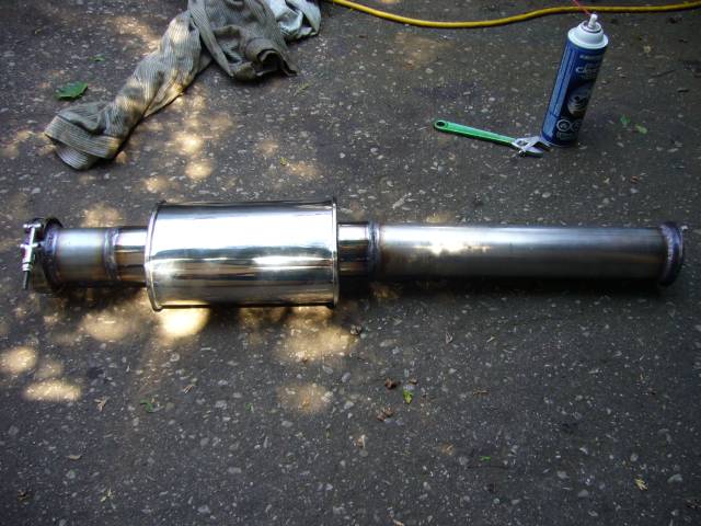
The midpipe is made from 3" stainless tubing. As fun as it was to drive the car around on a virtually open exhaust, it gets tiring quickly. The amusement starts to drain when you set off every car alarm on the street, police officers give you dirty looks, you have to yell at passengers to have a conversation and starting the car gives old men heart attacks in parking lots. To combat the noise I used a Vibrant Performance Ultra-Quiet 3" Straight Through Resonator. These are made of 3" stainless, have a straight through design (no restriction) and are packed with stainless mesh so even the heat of the rotary won't tear them up. Best of all, they work very well and are quite cheap.
Also notice that I've set up the entire exhaust with V-bands instead of flanges. I'm sick of exhaust leaks and V-bands are far easier to remove and reinstall. This will come in handy at the track as I will soon be fabricating a dump pipe that can be swapped onto the downpipe when racing. It's going to dump behind the passenger tire.
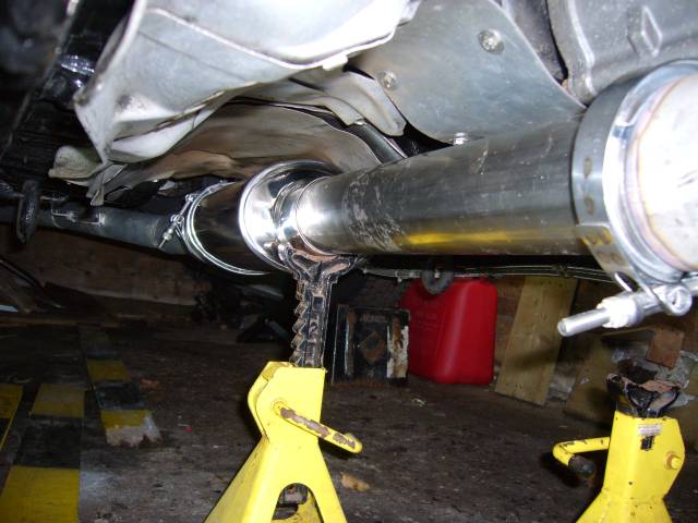
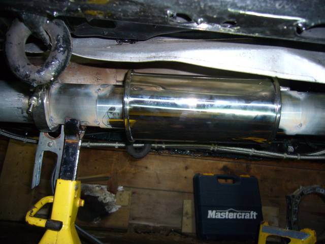
Here's a closeup of the resonator tacked into place. I put it far back from the super hot gasses at the end of the downpipe, and placed it so that it's within the factory heat shield for the stock cat. Also notice the V-band on the catback. I'm kind of disappointed with the ATP Turbo V-Band set. It's not that they are bad parts, but they could be better if they were made with stainless or had an inner lip like the Vibrant V-Bands. Also they were easily 1/16" loose on the 3" tubing I used, which made it a pain to keep lined up when welding. Other then that, they will certainly do the job.
At that point I also installed the bungs for the O2 sensors into the downpipe. The bung closest to the turbo is for the narrowband sensor (it needs to be kept warm) while the bung farther down is for the wideband sensor (it has it's own heater). The plug is in place to prevent damage to the threads during welding.
The midpipe and resonator were then fully welded. To keep the V-band flanges from warping, I kept the heat very low (around 50A) and installed a spare flange during welding. Seems to do the trick.
The midpipe is made from 3" stainless tubing. As fun as it was to drive the car around on a virtually open exhaust, it gets tiring quickly. The amusement starts to drain when you set off every car alarm on the street, police officers give you dirty looks, you have to yell at passengers to have a conversation and starting the car gives old men heart attacks in parking lots. To combat the noise I used a Vibrant Performance Ultra-Quiet 3" Straight Through Resonator. These are made of 3" stainless, have a straight through design (no restriction) and are packed with stainless mesh so even the heat of the rotary won't tear them up. Best of all, they work very well and are quite cheap.
Also notice that I've set up the entire exhaust with V-bands instead of flanges. I'm sick of exhaust leaks and V-bands are far easier to remove and reinstall. This will come in handy at the track as I will soon be fabricating a dump pipe that can be swapped onto the downpipe when racing. It's going to dump behind the passenger tire.
Here's a closeup of the resonator tacked into place. I put it far back from the super hot gasses at the end of the downpipe, and placed it so that it's within the factory heat shield for the stock cat. Also notice the V-band on the catback. I'm kind of disappointed with the ATP Turbo V-Band set. It's not that they are bad parts, but they could be better if they were made with stainless or had an inner lip like the Vibrant V-Bands. Also they were easily 1/16" loose on the 3" tubing I used, which made it a pain to keep lined up when welding. Other then that, they will certainly do the job.
At that point I also installed the bungs for the O2 sensors into the downpipe. The bung closest to the turbo is for the narrowband sensor (it needs to be kept warm) while the bung farther down is for the wideband sensor (it has it's own heater). The plug is in place to prevent damage to the threads during welding.
The midpipe and resonator were then fully welded. To keep the V-band flanges from warping, I kept the heat very low (around 50A) and installed a spare flange during welding. Seems to do the trick.
Thread Starter
Joined: Feb 2001
Posts: 29,798
Likes: 128
From: London, Ontario, Canada
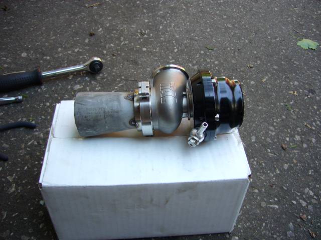
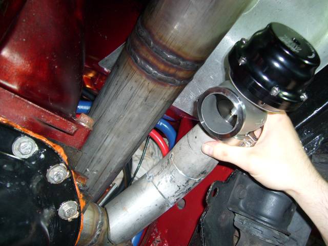
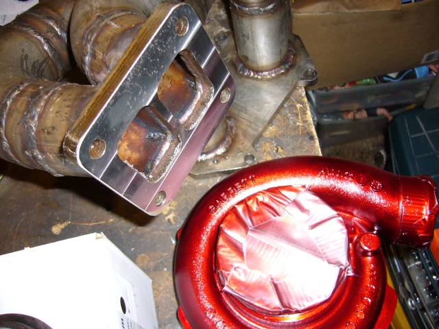
Now that the downpipe and midpipe were complete I knew where the wastegate could sit. The NA lower intake sticks out farther then the TII lower intake, and dictates that the wastegate must go near the frame rail while the downpipe needs to be nearer to the intake. Thus I waited until the downpipe was in place so I could get proper wastegate placement without any interference. The first step was to weld a 2" to 1.5" SCH 10 conical reducer to match the 2" manifold runners to the 1.5" wastegate flange on the Tial 44MM wastegate. Here it is tacked in place.
The position of the wastegate is determined primarily by fitting it in the available space while allowing the best flow from the manifold runners. I really had no interest in strange placement like in front of the manifold (requiring a long and complicated dump tube), on top of the frame rail (basically no space) or underneath the manifold (again, no real space). Also it could not interfere with installation of the downpipe or manifold nuts on the engine. Oh, and the wastegate outlet had to be positioned so that it was possible to route it back into the downpipe while accounting for movement during final welding.
After some test fitting, I ended up with a short section of pipe, leading to a 45 degree el. I found a wicked program online called Tubemiter that makes tube notching very easy. You enter your tubing or pipe dimensions into the software, tell it the angle at which you want the tube to meet, then it prints out a template. This template gets wrapped around the tube and you then trace your pattern and cut it out with the metal cutting implement of your choice. Very slick and it sure saved a hell of a lot of time on the grinder.
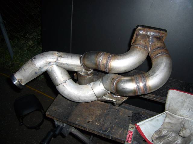
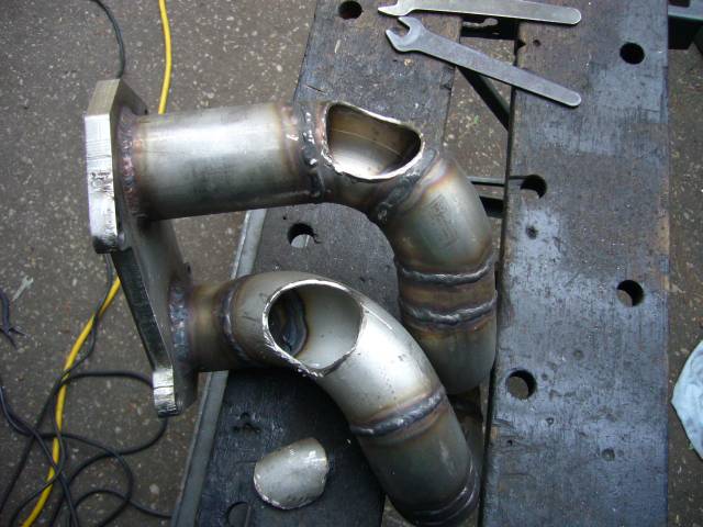
With the first wastegate runner in place, the whole assembly could come off of the car so the 2nd runner could be constructed. I'm not entirely happy with these runners. Ideally wastegate runners should meet the manifold runners are very shallow angles and form a nice Y, not an almost 90 degree T as these do. However the one saving grace with these runners is that they connect to the outside of a bend, so I suspect that gas flow will not be compromised as much as it could be.
Holes were then cut into the manifold runners to allow the exhaust gasses to actually flow into the wastegate runners. I wonder if anyone has ever been so eager to weld on the runners that they forget this step?
The position of the wastegate is determined primarily by fitting it in the available space while allowing the best flow from the manifold runners. I really had no interest in strange placement like in front of the manifold (requiring a long and complicated dump tube), on top of the frame rail (basically no space) or underneath the manifold (again, no real space). Also it could not interfere with installation of the downpipe or manifold nuts on the engine. Oh, and the wastegate outlet had to be positioned so that it was possible to route it back into the downpipe while accounting for movement during final welding.
After some test fitting, I ended up with a short section of pipe, leading to a 45 degree el. I found a wicked program online called Tubemiter that makes tube notching very easy. You enter your tubing or pipe dimensions into the software, tell it the angle at which you want the tube to meet, then it prints out a template. This template gets wrapped around the tube and you then trace your pattern and cut it out with the metal cutting implement of your choice. Very slick and it sure saved a hell of a lot of time on the grinder.
With the first wastegate runner in place, the whole assembly could come off of the car so the 2nd runner could be constructed. I'm not entirely happy with these runners. Ideally wastegate runners should meet the manifold runners are very shallow angles and form a nice Y, not an almost 90 degree T as these do. However the one saving grace with these runners is that they connect to the outside of a bend, so I suspect that gas flow will not be compromised as much as it could be.
Holes were then cut into the manifold runners to allow the exhaust gasses to actually flow into the wastegate runners. I wonder if anyone has ever been so eager to weld on the runners that they forget this step?
Thread Starter
Joined: Feb 2001
Posts: 29,798
Likes: 128
From: London, Ontario, Canada
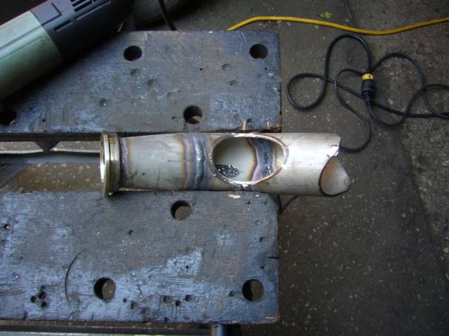
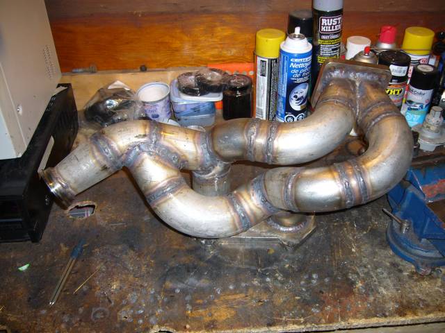
Here's the hole in the rear wastegate runner where the front runner meets it. The two pipes meet at a sharp angle but this passage is huge so I don't expect any flow issues.
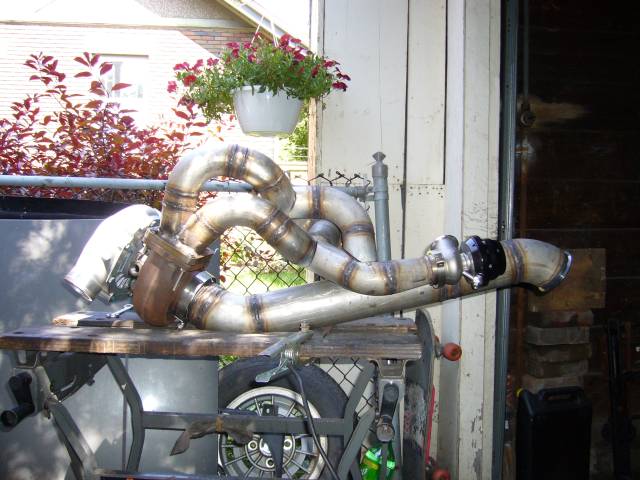
I couldn't resist mocking the whole thing up on the bench.
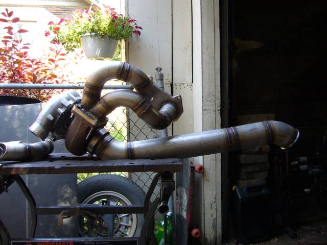
Here's the mockup with the wastegate runners tacked back into place. There is way too much plumbing here! And there's still more to add. Next time, I'm going back to NA...
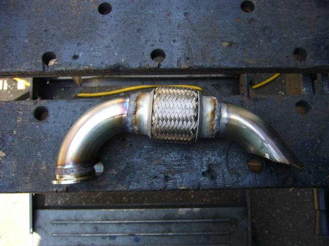
Time to fully weld the wastegate runners. Some of those angles were a real pain in the butt due to the lack of space. I had to seriously extend the tungsten out of the torch to get at the inner joints which necessitated cranking the gas flow as well to keep the shield. Glad I don't do that very often.
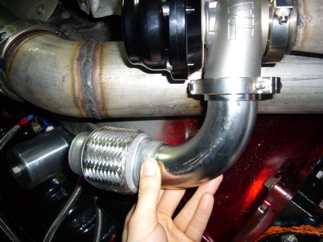
The manifold, turbo and downpipe were then reinstalled on the car and the work on the wastegate dump started. It starts off as an approximately 90 degree bend of 1.5" tubing from the flange, then connects to a short flex section. The flex section is almost necessary as it is absolute hell to reassemble everything without give somewhere. Stainless loves to move when welding and unless there is serious jigging present, stuff isn't going to fit after being full welded no matter how well you tack. Because of this movement, I finish welded every joint before I started work on the next section.
I couldn't resist mocking the whole thing up on the bench.
Here's the mockup with the wastegate runners tacked back into place. There is way too much plumbing here! And there's still more to add. Next time, I'm going back to NA...
Time to fully weld the wastegate runners. Some of those angles were a real pain in the butt due to the lack of space. I had to seriously extend the tungsten out of the torch to get at the inner joints which necessitated cranking the gas flow as well to keep the shield. Glad I don't do that very often.
The manifold, turbo and downpipe were then reinstalled on the car and the work on the wastegate dump started. It starts off as an approximately 90 degree bend of 1.5" tubing from the flange, then connects to a short flex section. The flex section is almost necessary as it is absolute hell to reassemble everything without give somewhere. Stainless loves to move when welding and unless there is serious jigging present, stuff isn't going to fit after being full welded no matter how well you tack. Because of this movement, I finish welded every joint before I started work on the next section.
Thread Starter
Joined: Feb 2001
Posts: 29,798
Likes: 128
From: London, Ontario, Canada
Even though I finish welded every joint as it was made, I did some tacking because the parts kept falling on my head. That gets annoying after a while.
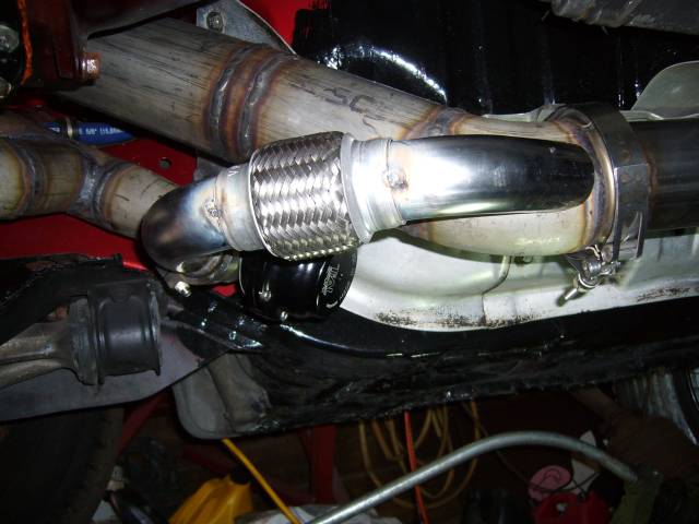
Another view of the wastegate dump.
The flex section was then fully welded. I'm a little disappointed with the Vibrant 1.75" Flex Coupling with regards to quality. While the inner pipe and braiding are stainless, the outer crimp section appears to be galvanized steel. And it sure smelled like galvanized steel during welding. The galvanization is very dirty and makes controlling the TIG arc and puddle very difficult. Also that means it will rust down the road, so it will need to be painted.
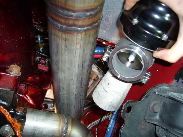
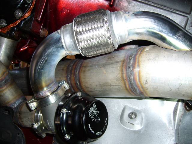
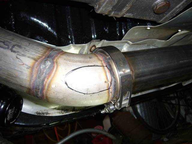
With the flex section welded, the position on the downpipe was known so the downpipe could then be marked for the cutout. Notice how shallow of an angle the two pipes meet at. It's very important to have the wastegate dump flow smoothly into the downpipe and not become a venturi. But it does mean that welding the inner angle is a pain.
Welding the dump to the downpipe was generally straightforward. A little challenging welding the thin tube to the thick pipe, but this is where TIG really excels. Really, the only annoying part was the V section between the 45 degree bend and downpipe.
Another view of the wastegate dump.
The flex section was then fully welded. I'm a little disappointed with the Vibrant 1.75" Flex Coupling with regards to quality. While the inner pipe and braiding are stainless, the outer crimp section appears to be galvanized steel. And it sure smelled like galvanized steel during welding. The galvanization is very dirty and makes controlling the TIG arc and puddle very difficult. Also that means it will rust down the road, so it will need to be painted.
With the flex section welded, the position on the downpipe was known so the downpipe could then be marked for the cutout. Notice how shallow of an angle the two pipes meet at. It's very important to have the wastegate dump flow smoothly into the downpipe and not become a venturi. But it does mean that welding the inner angle is a pain.
Welding the dump to the downpipe was generally straightforward. A little challenging welding the thin tube to the thick pipe, but this is where TIG really excels. Really, the only annoying part was the V section between the 45 degree bend and downpipe.
Thread Starter
Joined: Feb 2001
Posts: 29,798
Likes: 128
From: London, Ontario, Canada
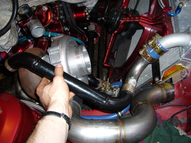
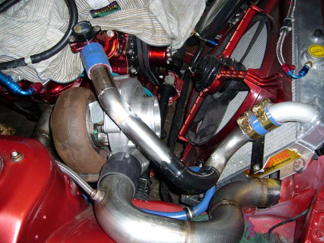
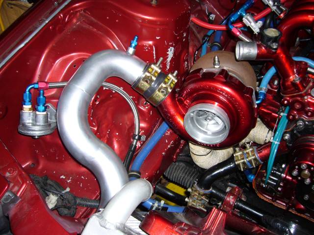
The GT40R dominates the engine bay which necessitated the re-engineering of the upper coolant pipe. The previous pipe basically copied the stock hose and while it did fit, it left absolutely no room for an air filter. After about an hour of trying to figure out the new pipe (including some strange efforts with U bends) I finally got it sorted by adding a 90 degree bend at the radiator, then joining up the original upper pipe at that point. A little bit of modification to the other end and it almost fell into place.
I trimmed down the length of the old pipe and removed the almost 90 degree bend closest to the engine. Then used a small section of a previously cut bend to point the pipe towards the water neck. After that, a short section of straight tube was used. Tacks hold it in place for now.
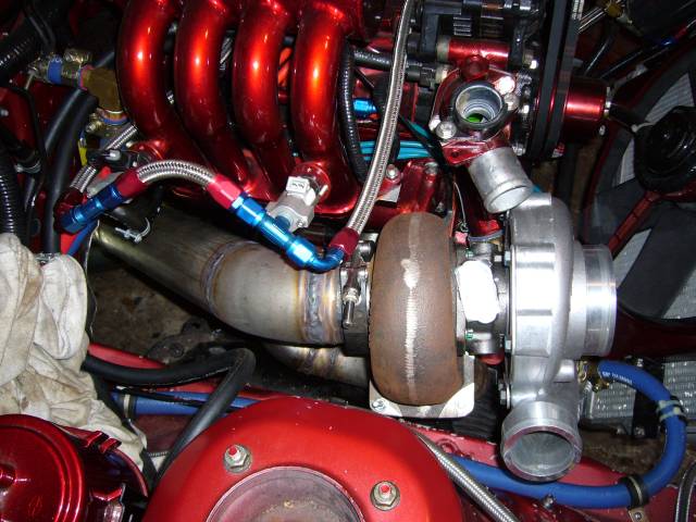
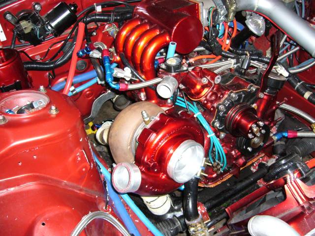
Something that really bothers me is the rust forming on the turbine housing. That rust is just from a few weeks exposure to open air, and handling. Now I know it might be a bit of a nitpick, but when you pay this much for a turbo, you at least expect it to look decent. Is it to much to ask for Garrett use some kind of coating on the castings? Even a thin plating of almost anything would prevent the rust.
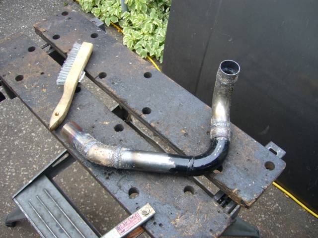
The pipe was then brought over to the bench to be welded. Just before I started working on this pipe I had to take the rental TIG back, so we're back to the trusty flux core wire feeder. Hence the splatter. Nothing that a flap wheel won't cure. Beads were also welded around the ends of the pipe to give the clamps something to grip.
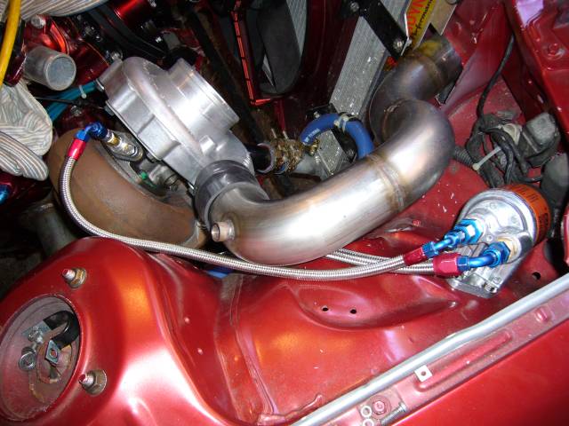
Keeping in mind that this is an NA block, the oil source for the turbo is a bung that I had installed on the oil cooler. The downside of this approach is that the turbo receives unfiltered oil and it is entirely possible for the oil pump to pick up some nasties from the bottom of the pan (gasket sealer, metal chips, etc.). Sending that stuff through a ball bearing turbo would not be my first choice. To combat this problem I decided to use a remote mount oil filter kit as a secondary oil filter. The large -6 feed comes from the cooler, and the small -4 feed goes out to the turbo.
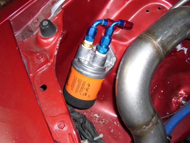
With the lines made up you can see basic idea.
I trimmed down the length of the old pipe and removed the almost 90 degree bend closest to the engine. Then used a small section of a previously cut bend to point the pipe towards the water neck. After that, a short section of straight tube was used. Tacks hold it in place for now.
Something that really bothers me is the rust forming on the turbine housing. That rust is just from a few weeks exposure to open air, and handling. Now I know it might be a bit of a nitpick, but when you pay this much for a turbo, you at least expect it to look decent. Is it to much to ask for Garrett use some kind of coating on the castings? Even a thin plating of almost anything would prevent the rust.
The pipe was then brought over to the bench to be welded. Just before I started working on this pipe I had to take the rental TIG back, so we're back to the trusty flux core wire feeder. Hence the splatter. Nothing that a flap wheel won't cure. Beads were also welded around the ends of the pipe to give the clamps something to grip.
Keeping in mind that this is an NA block, the oil source for the turbo is a bung that I had installed on the oil cooler. The downside of this approach is that the turbo receives unfiltered oil and it is entirely possible for the oil pump to pick up some nasties from the bottom of the pan (gasket sealer, metal chips, etc.). Sending that stuff through a ball bearing turbo would not be my first choice. To combat this problem I decided to use a remote mount oil filter kit as a secondary oil filter. The large -6 feed comes from the cooler, and the small -4 feed goes out to the turbo.
With the lines made up you can see basic idea.
Thread Starter
Joined: Feb 2001
Posts: 29,798
Likes: 128
From: London, Ontario, Canada
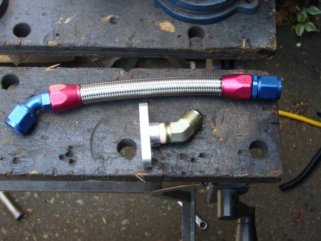
This turbo requires a different drain setup then the stocker, so I made up a new drain line from -10 hose and the appropriate fittings. The drain flange is from ATP Turbo and provides a 1/2" NPT thread for whatever adapter the user chooses. ATP has recently expanded their line of turbo feed and drain flanges to include built in AN flares and restrictors.
Test fitting the turbo oil line. Maybe some of the photographers around here can tell me how to get decent pictures when using the flash? The flash always blows out the details and makes my welds look disgusting. Also take a look at the wicked warp of the turbo flange...The machine shop guys are going to have fun with that!
Speaking of the machine shop, I'd like to thank Mike Prince of Prince Machine for milling my flanges when no other shop in the city was willing to take on such a small job. He spent a few hours jigging it up and I was very happy with the outcome as well as the $125 cost. He said that he machined it within 0.001, which is certainly acceptable! While the manifold was at the machine shop, I also painted the turbo compressor housing. MetalCast red, naturally.
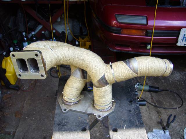
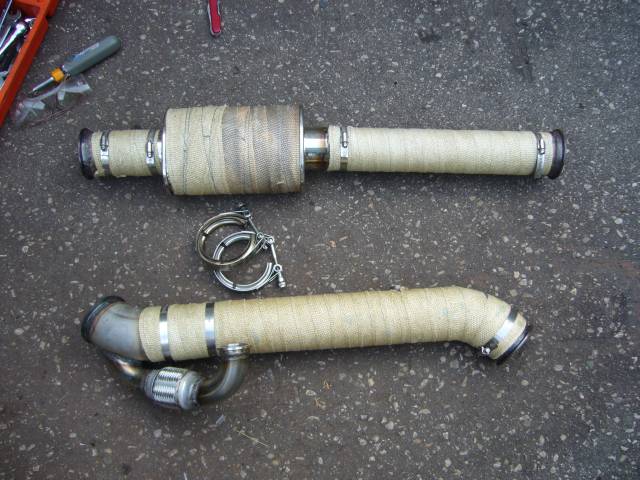
To keep underhood temps sane, I heat wrapped the entire exhaust system. Here's the manifold. The only annoyance with heat wrap is that it's not really designed to cover an area where one pipe merges into another, so there are a few spots left bare. Such is life. Maybe I'll go back later and add another layer.
The key with heat wrap is to get it nice and wet before wrapping. Wrap a few turns on one end and then use a tie to secure it in place. Now pull it tight and continue wrapping to the other end. Hold it tight with your full hand by gripping around the tube and use your other hand to install the tie. When it dries, it will tighten up and won't come off. After the wrap dries, I also wrap the entire piece in bailing wire as an extra measure.
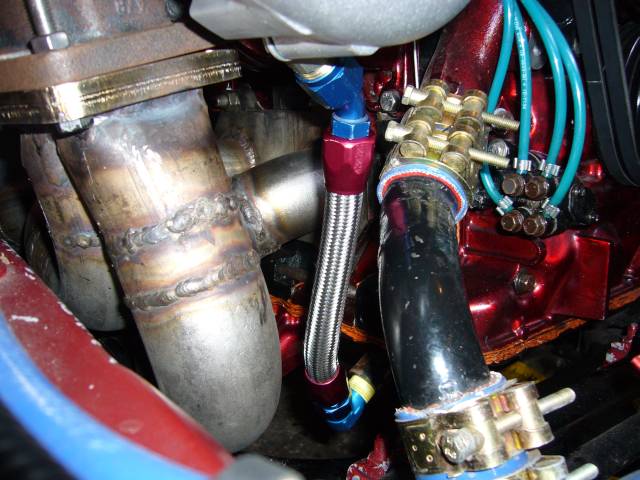
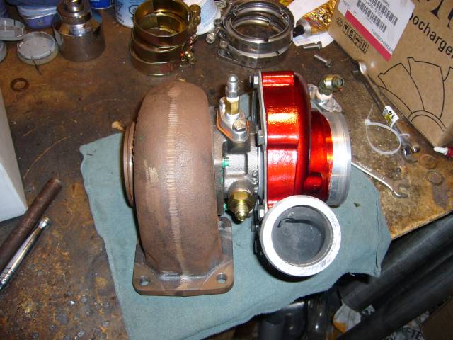
Here's the turbo with the fluid fittings installed. The oil feed is an ATP T4 feed flange. This flange has a 1/8" NPT thread. Screwed into this thread is an oil restrictor (0.40" I think), and from there a 1/8" NPT to -4 AN adapter. The oil restrictor is very important. Without it, the turbo will blow oil. The water feed passages on the GT40R are M18 x 1.5, so a trip to the local hydraulic store scored some adapters to -6 that I sealed with Teflon sealant and copper crush washers. ATP also stocks these, but I forgot to order them when I ordered the other stuff.
Test fitting the turbo oil line. Maybe some of the photographers around here can tell me how to get decent pictures when using the flash? The flash always blows out the details and makes my welds look disgusting. Also take a look at the wicked warp of the turbo flange...The machine shop guys are going to have fun with that!
Speaking of the machine shop, I'd like to thank Mike Prince of Prince Machine for milling my flanges when no other shop in the city was willing to take on such a small job. He spent a few hours jigging it up and I was very happy with the outcome as well as the $125 cost. He said that he machined it within 0.001, which is certainly acceptable! While the manifold was at the machine shop, I also painted the turbo compressor housing. MetalCast red, naturally.
To keep underhood temps sane, I heat wrapped the entire exhaust system. Here's the manifold. The only annoyance with heat wrap is that it's not really designed to cover an area where one pipe merges into another, so there are a few spots left bare. Such is life. Maybe I'll go back later and add another layer.
The key with heat wrap is to get it nice and wet before wrapping. Wrap a few turns on one end and then use a tie to secure it in place. Now pull it tight and continue wrapping to the other end. Hold it tight with your full hand by gripping around the tube and use your other hand to install the tie. When it dries, it will tighten up and won't come off. After the wrap dries, I also wrap the entire piece in bailing wire as an extra measure.
Here's the turbo with the fluid fittings installed. The oil feed is an ATP T4 feed flange. This flange has a 1/8" NPT thread. Screwed into this thread is an oil restrictor (0.40" I think), and from there a 1/8" NPT to -4 AN adapter. The oil restrictor is very important. Without it, the turbo will blow oil. The water feed passages on the GT40R are M18 x 1.5, so a trip to the local hydraulic store scored some adapters to -6 that I sealed with Teflon sealant and copper crush washers. ATP also stocks these, but I forgot to order them when I ordered the other stuff.
Trending Topics
Thread Starter
Joined: Feb 2001
Posts: 29,798
Likes: 128
From: London, Ontario, Canada
Once the heat wrap dried, the manifold was bolted to the engine. I used new stainless nuts as well as some nasty serrated stainless lock washers. I would have used the copper turbo locknuts but there was not enough clearance to use a socket to tighten them. If you attempt to tighten the copper nuts with an open ended wrench, they will easily round off. Of course, anti seize is used on all the fasteners.
Now it was the moment of truth. In order to gain access to the turbo mounting flange with a wrench, I had to pull the compressor housing again. You can see that some creative wrench work was needed to reach the nuts. I was torn between installing studs on the turbo flange or using bolts and nuts. I ended up using M8 stainless nuts and bolts (with lock washers) due to space issues.
.jpg)
The downpipe and midpipe were heat wrapped along with the manifold. I cheaped out and used hose clamps to secure the wrap instead of the stainless ties. Also the hose clamps are much easier to work with and have less of a chance of cutting you up when you install them (those stainless zip-ties are sharp!).
Before the water and oil lines are installed, the compressor housing had to be remounted. Otherwise there would be no access to the bolts.
Here are the turbo water supply lines. I replaced the previous fuel injection lines with Russel "Twist Lock" hose, but I'm starting to wish that I had not. I didn't use regular braided stainless because the other end of the hose needed to be clamped to the rear iron and water pump nipples. In my experience, braided stainless does not clamp well. The Twist Lock hose was specifically designed for installation over a nipple. However it is a nightmare to work with. The idea is that the hose pushes onto a barbed nipple with a standard AN flare at the other end. In practice, this is nearly impossible to do without possessing superhuman strength. I'm sure on some level this hose works if you use the proper lubricant, spend 6 hours at day at the gym and have a lot of practice, but until then I'll be sticking with my regular braided stainless. I could only manage to get the hose about 3/4 of the way on, so I had to resort to horrible hose clamps. Not even the T-bolt style EFI clamps would do the job as the hose has an odd sized outer diameter. They look like they will hold but this still makes me nervous. Next time I have the upper intake off, I'll tap the block and water pump housing for 1/4" NPT and go with braided stainless.
Now it was the moment of truth. In order to gain access to the turbo mounting flange with a wrench, I had to pull the compressor housing again. You can see that some creative wrench work was needed to reach the nuts. I was torn between installing studs on the turbo flange or using bolts and nuts. I ended up using M8 stainless nuts and bolts (with lock washers) due to space issues.
The downpipe and midpipe were heat wrapped along with the manifold. I cheaped out and used hose clamps to secure the wrap instead of the stainless ties. Also the hose clamps are much easier to work with and have less of a chance of cutting you up when you install them (those stainless zip-ties are sharp!).
Before the water and oil lines are installed, the compressor housing had to be remounted. Otherwise there would be no access to the bolts.
Here are the turbo water supply lines. I replaced the previous fuel injection lines with Russel "Twist Lock" hose, but I'm starting to wish that I had not. I didn't use regular braided stainless because the other end of the hose needed to be clamped to the rear iron and water pump nipples. In my experience, braided stainless does not clamp well. The Twist Lock hose was specifically designed for installation over a nipple. However it is a nightmare to work with. The idea is that the hose pushes onto a barbed nipple with a standard AN flare at the other end. In practice, this is nearly impossible to do without possessing superhuman strength. I'm sure on some level this hose works if you use the proper lubricant, spend 6 hours at day at the gym and have a lot of practice, but until then I'll be sticking with my regular braided stainless. I could only manage to get the hose about 3/4 of the way on, so I had to resort to horrible hose clamps. Not even the T-bolt style EFI clamps would do the job as the hose has an odd sized outer diameter. They look like they will hold but this still makes me nervous. Next time I have the upper intake off, I'll tap the block and water pump housing for 1/4" NPT and go with braided stainless.
Thread Starter
Joined: Feb 2001
Posts: 29,798
Likes: 128
From: London, Ontario, Canada
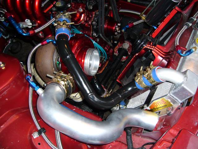
The turbo outlet pipe installed easily with silicone couplers and T-bolt clamps.
Next installed was the turbo oil feed line.

Then the upper coolant pipe. The silicone couplers are made from sections of 1.5" ThermoPol silicone heater hose.
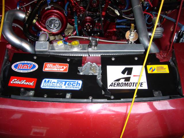
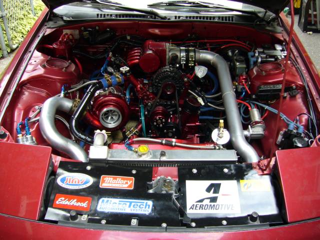
I figured it was time to clean up the front of the car so I installed the rad panels. Afterwards the big black panel looked too barren so I put on a bunch of stickers. Yes, every one of those stickers actually represents a product that's on the car. I wish Tial made smaller stickers because the big Aeromotive decal left no space for Tial.
V-Bands make exhaust work very easy. In a few minutes, the downpipe went into place.
Next installed was the turbo oil feed line.
Then the upper coolant pipe. The silicone couplers are made from sections of 1.5" ThermoPol silicone heater hose.
I figured it was time to clean up the front of the car so I installed the rad panels. Afterwards the big black panel looked too barren so I put on a bunch of stickers. Yes, every one of those stickers actually represents a product that's on the car. I wish Tial made smaller stickers because the big Aeromotive decal left no space for Tial.
V-Bands make exhaust work very easy. In a few minutes, the downpipe went into place.
Last edited by Aaron Cake; Jul 18, 2007 at 04:10 PM.
Thread Starter
Joined: Feb 2001
Posts: 29,798
Likes: 128
From: London, Ontario, Canada
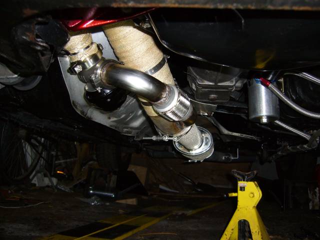
The wastegate and wastegate dump was next. I was very relieved that everything still fit after all the welding and machining. The flex pipe actually took very little flexing to get into position.
When everything has V-bands, the strategy is to leave them all a little loose until they are all installed, then tighten in stages. If you just crank down on them one at a time you'll never get things lined up.
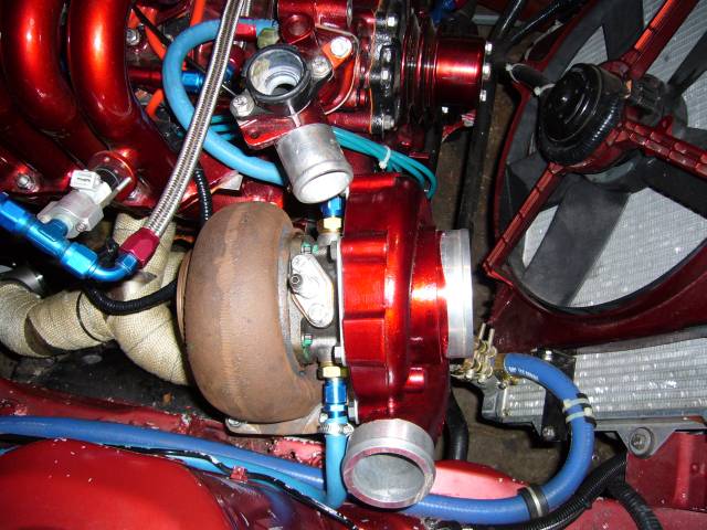
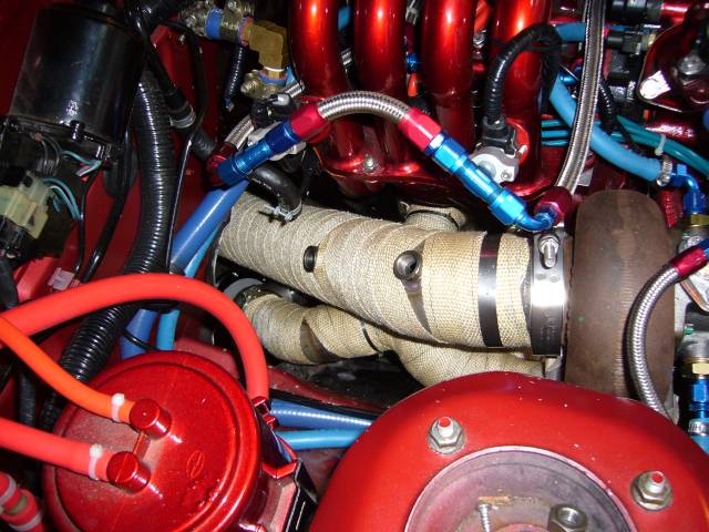
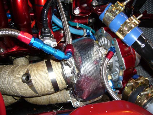
To keep the turbine housing from baking everything around it, I installed a DEI turbo blanket. It cost under $90 and came with a long section of 6" wide exhaust wrap (to wrap the turbine housing), the outer aluminized insulating blanket, two 20" ties, two 10" ties and a good amount of 2" wrap to cover the downpipe. All in all, a very good deal. The instructions sucked and worried me a little in the sense that it looked like a real bitch to install the thing, but I was surprised at how easily it went on and how well it fit. Certainly money well spent. Looks pretty damn bitchin' as well.
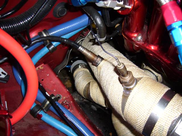
The Microtech uses a narrow band O2 sensor (top), while the Nexus Wideband gauge uses a (duh) wideband sensor. A little anti-seize on the threads keeps them from getting stuck.
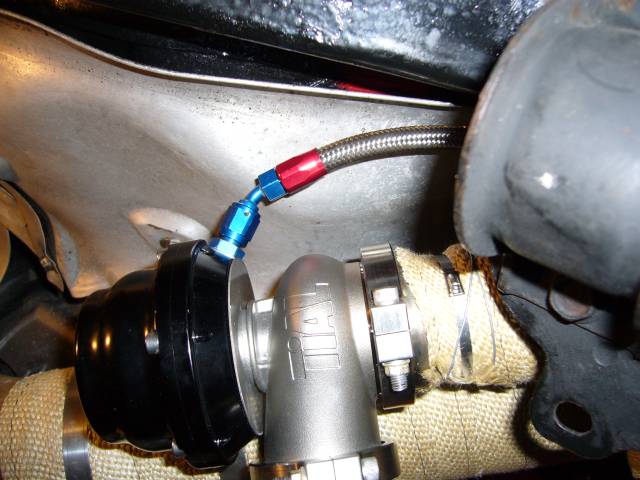
A few years ago when tuning a car, I nearly blew up someone else's engine because their silicone wastegate line popped off. That problem should not exist on this car due to the use of -4 braided stainless line and AN fittings. When I install a boost controller, it should be no trouble adapting the hose by changing ends. For now, the wastegate is just running naturally on the 0.9 bar spring.
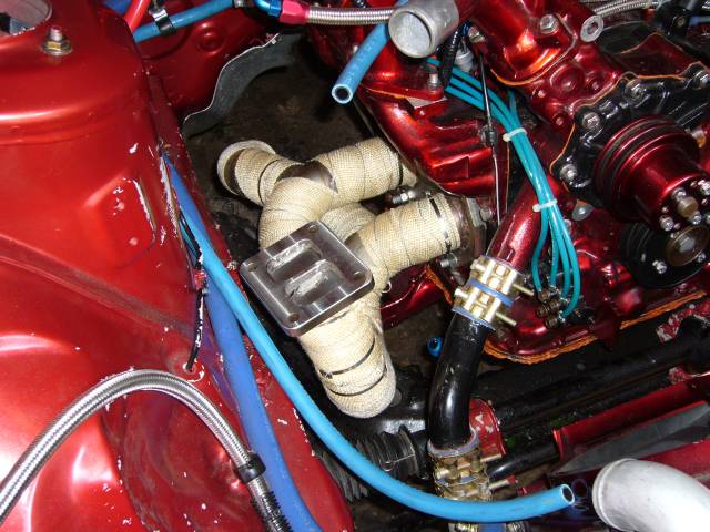
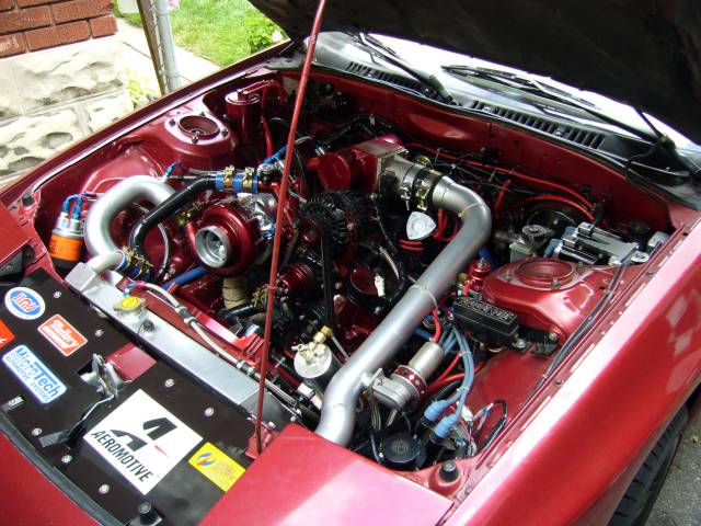
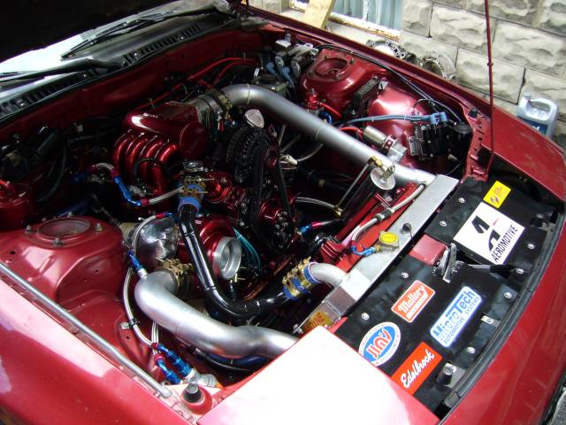
That was the last hose to be installed! With that, the engine bay was complete. Now I was still waiting for an air filter when I took this picture, but since then a smaller K&N "muffin" unit has been installed. It's been a hell of a lot of work getting the engine bay to this point, but for the most part it's now complete.
Really, I don't think many people appreciate how much work is involved in a custom big-turbo setup. Things are easy when you buy off the shelf. There's about 2 months of fab work in that engine bay just for the turbo manifold, downpipe, midpipe and intercooler piping, working 8 hours a day on weekends and several hours a night on weeknights.
When everything has V-bands, the strategy is to leave them all a little loose until they are all installed, then tighten in stages. If you just crank down on them one at a time you'll never get things lined up.
To keep the turbine housing from baking everything around it, I installed a DEI turbo blanket. It cost under $90 and came with a long section of 6" wide exhaust wrap (to wrap the turbine housing), the outer aluminized insulating blanket, two 20" ties, two 10" ties and a good amount of 2" wrap to cover the downpipe. All in all, a very good deal. The instructions sucked and worried me a little in the sense that it looked like a real bitch to install the thing, but I was surprised at how easily it went on and how well it fit. Certainly money well spent. Looks pretty damn bitchin' as well.
The Microtech uses a narrow band O2 sensor (top), while the Nexus Wideband gauge uses a (duh) wideband sensor. A little anti-seize on the threads keeps them from getting stuck.
A few years ago when tuning a car, I nearly blew up someone else's engine because their silicone wastegate line popped off. That problem should not exist on this car due to the use of -4 braided stainless line and AN fittings. When I install a boost controller, it should be no trouble adapting the hose by changing ends. For now, the wastegate is just running naturally on the 0.9 bar spring.
That was the last hose to be installed! With that, the engine bay was complete. Now I was still waiting for an air filter when I took this picture, but since then a smaller K&N "muffin" unit has been installed. It's been a hell of a lot of work getting the engine bay to this point, but for the most part it's now complete.
Really, I don't think many people appreciate how much work is involved in a custom big-turbo setup. Things are easy when you buy off the shelf. There's about 2 months of fab work in that engine bay just for the turbo manifold, downpipe, midpipe and intercooler piping, working 8 hours a day on weekends and several hours a night on weeknights.
Joined: May 2002
Posts: 5,972
Likes: 37
From: Ottawa, Soviet Canuckistan
It's about time 
I was down at Joe's shop on the weekend and was asking him "hey have you guys heard from Aaron Cake lately? I haven't heard from him since he posted the vid of that first startup"
 Good to hear things are going well. It's been one hell of a project to see come together.
Good job man, can't wait to see it.
Jon
I was down at Joe's shop on the weekend and was asking him "hey have you guys heard from Aaron Cake lately? I haven't heard from him since he posted the vid of that first startup"
Good to hear things are going well. It's been one hell of a project to see come together.Good job man, can't wait to see it.
Jon
Damn, another classic thread from you Aaron! I'm very Impressed. To think I was going to PM you to ask you about yourself and your car - and now this thread.
What you are doing with the bungs to your DP Is what I have to do to mine. The WB needs to be plumbed. What are the specs to It? Where and how much did you get yours for?
Nice job!
What you are doing with the bungs to your DP Is what I have to do to mine. The WB needs to be plumbed. What are the specs to It? Where and how much did you get yours for?
Nice job!


Thread Starter
Joined: Feb 2001
Posts: 29,798
Likes: 128
From: London, Ontario, Canada
[/quote]
What you are doing with the bungs to your DP Is what I have to do to mine. The WB needs to be plumbed. What are the specs to It? Where and how much did you get yours for?
Nice job!
Nice job!
The wideband is part of AutoMeter's Nexus line to go along with the rest of my gauges. It was...not really cheap, as with many of the Nexus gauges. My only real annoyance with it is that there is no simulated narrowband output, or 0-5V output. Something that costs so much should have these necessities.
The wastegate is a 44MM Tial that I purchased from ATP Turbo. I believe the price was around $360 or so.
It also seems that the bottom was chopped off this thread somehow. Here's the last missing post:
So now you're probably wondering "Where's the video?". Well, there isn't one. To make a long story short I just finished up around 5PM on Sunday. After setting up the camera and making my introductions, I tried to start the car and....nothin'. It started, then stalled. Then started, then stalled. Connected up the laptop to tweak the fuel maps and could not manage to communicate with the Microtech. After an hour of troubleshooting I was frustrated enough that I just put the car back in the garage and made dinner. Turns out that I'm a complete assclown and forgot to use the laptop adapter necessary to connect to the Microtech! Well damn.
Monday night I installed the air filter, put the insurance info in the glovebox and with my laptop adapter in hand, we started the car. Fired first try and settled down to it's typical idle after some warming up. A/F ratios according to the wideband were actually very good, considering I did all my tuning last fall with the narrowband. Idle was right around 13.5:1, and light throttle was a littler rich at 12:1.
After checking for leaks, we set about driving the car for some basic tuning. An hour or so was spent cleaning up the light load section of the map now that there was A/F ratio feedback available with the wideband and the car now drives brilliantly. Easily cruises along at 2,000 RPM in 5th gear with no drama and A/F ratios in the high 13s. Still a bit rich for my tastes so some more time will be spent to clean things up.
What stuck me most was how easily the turbo responds. We only tuned up to a few PSI, but even then it was obvious that the turbo has a lot in it. Boost response is very good and spool at even light throttles is very impressive for such a large unit. Overall I'd say it responds approximately equal to a HT-18 on a stock port car. But the sound! Oh, so sexy! Even at just above atmospheric pressure the turbo howls in such a satisfying way. I can't wait until I have some time to really tune the car so it can see some real boost. At less then 10 PSI, the GT40R is still practically asleep. Actual tuning is expected to take place within a week or so, mainly on the (deserted) street. Then it's time to hit the dyno.
I promise to have a few videos available soon. I'll put up my botched startup attempt and edit it together with a good startup. Also I may mount a camera in the engine bay and go for a drive so people can see and hear the turbo.
What's next? Well, the car still needs an interior and suspension, but for now I'm just going to enjoy it as it is and then deal with those details over the winter.
Patience! You know you can't rush quality. Two years In the making and still going strong. Should have It this weekend, as I'm told. Woot!
Oh, sorry Aaron. I was referring to the specs of the bungs used for both narrow and wide band O2 sensors. If you remember, I'm using the AEM one that I showed you last time.
Rephrased: What are the specs to the O2 sensor bungs? Where and how much did you get yours for? I'm going to need a handful of them for my RB DP ad custom one.
Originally Posted by IAN
I would be interested in coming down to watch you dyno tune
Thread Starter
Joined: Feb 2001
Posts: 29,798
Likes: 128
From: London, Ontario, Canada
Rephrased: What are the specs to the O2 sensor bungs? Where and how much did you get yours for? I'm going to need a handful of them for my RB DP ad custom one.
