
Early Summer 2007 Pics/Updates On My Turbo-NA Bridgeport Project

Thread Starter
Joined: Feb 2001
Posts: 29,798
Likes: 128
From: London, Ontario, Canada
Early Summer 2007 Pics/Updates On My Turbo-NA Bridgeport Project
It's been a while since the last update of my Turbo-NA bridgeport project (project Tina) and with 41 more pictures, I figure we're about due. If you are just tuning in, make sure to read the threads from the beginning. Grab a drink, get comfortable and take a look at the 2nd Gen Projects Thread for links to the past threads (as well as a lot of other interesting projects).
Last time we sort of left off in a bit of frustration dealing with a defective o-ring on the Mallory fuel filter, and having issues getting insurance. The o-ring issue was solved with a local replacement, and insurance was obtained after jumping through some hoops.
With the mechanical glitches fixed, I was actually able to drive the car for the first time in about 4 years for the remainder of November and a little bit of December. I used this time to break in the engine and tune the low load areas in the fuel map. Once the weather turned cold and snow as imminent, the car was garaged and the work you see in this thread began...
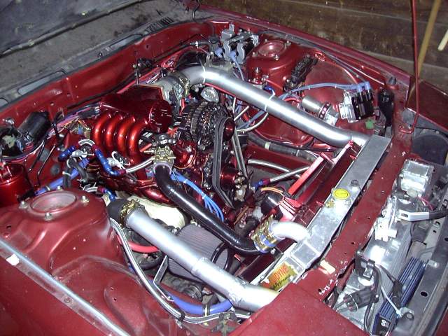
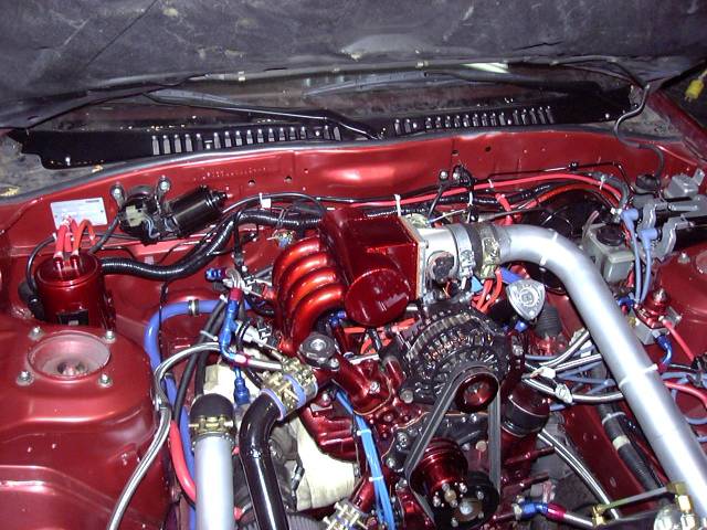
The previous thread left off with a shot of the passenger side of the engine bay, completed and ready for the first startup.
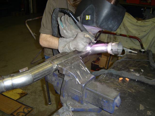
This image should have been in the last thread, but it took a while for the person behind the camera to email me the image. It's rare that there's an actual whole picture of me in one of these threads, so I present a picture of myself TIG welding the intercooler outlet pipe.
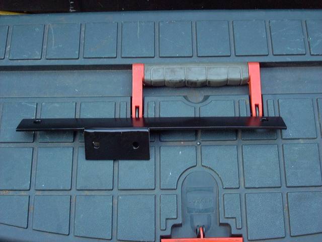
Before the car could be driven, a few minor tasks needed to be completed. One of them was to mount a coolant recovery bottle. Here's the aluminum bracket I made to mount it to the side of the e-fan.
The coolant bottle was then installed. It was not plumbed at this time as I was waiting for some fittings to come in.
After the bottle was mounted, I loomed and wrapped the wiring harness. There are a lot of ways to do this but I prefer to keep it simple; the wires get put into split loom corrugated tubing, and then the tubing is wrapped with heat and oil resistant electrical tape. I tend not to run wires past major heat sources so I've generally not found the need for thermal wrap. I've also included a few extra wires in the harness in case I need to make additions later.
Last time we sort of left off in a bit of frustration dealing with a defective o-ring on the Mallory fuel filter, and having issues getting insurance. The o-ring issue was solved with a local replacement, and insurance was obtained after jumping through some hoops.
With the mechanical glitches fixed, I was actually able to drive the car for the first time in about 4 years for the remainder of November and a little bit of December. I used this time to break in the engine and tune the low load areas in the fuel map. Once the weather turned cold and snow as imminent, the car was garaged and the work you see in this thread began...
The previous thread left off with a shot of the passenger side of the engine bay, completed and ready for the first startup.
This image should have been in the last thread, but it took a while for the person behind the camera to email me the image. It's rare that there's an actual whole picture of me in one of these threads, so I present a picture of myself TIG welding the intercooler outlet pipe.
Before the car could be driven, a few minor tasks needed to be completed. One of them was to mount a coolant recovery bottle. Here's the aluminum bracket I made to mount it to the side of the e-fan.
The coolant bottle was then installed. It was not plumbed at this time as I was waiting for some fittings to come in.
After the bottle was mounted, I loomed and wrapped the wiring harness. There are a lot of ways to do this but I prefer to keep it simple; the wires get put into split loom corrugated tubing, and then the tubing is wrapped with heat and oil resistant electrical tape. I tend not to run wires past major heat sources so I've generally not found the need for thermal wrap. I've also included a few extra wires in the harness in case I need to make additions later.
Thread Starter
Joined: Feb 2001
Posts: 29,798
Likes: 128
From: London, Ontario, Canada
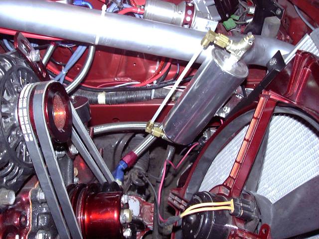
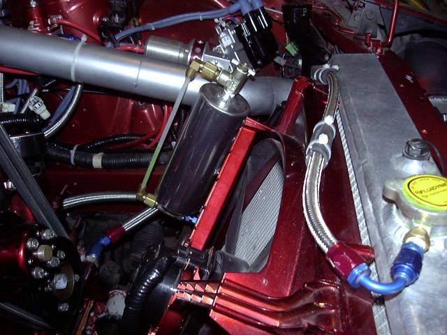
Once the fittings arrived I made a -4 braided stainless line to bring coolant to the recovery bottle. The hole at the pressure cap of the Fluidyne rad is actually tiny 1/16 NPT, so a trip to the hydraulic store was necessary for an adapter to convert it to the more standard 1/8" NPT. From there, a 1/8" NPT to -4 flare adapter allows connection of a 120 degree -4 hose end. The other end connects to the bottom of the recovery bottle via a 90 degree -4 hose end and a -4 flare to 1/4" NPT adapter.
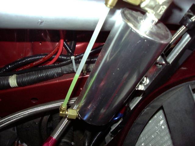
Here's a closeup showing the wicked-cool sight glass I had the hydraulic shop piece together for the coolant bottle. They used some opaque nylon tubing, and an assortment of fittings to put it together.
And at that point, I could drive the car. So I did. I put about 600KM on it before the winter and thoroughly enjoyed doing so. The car at that point was very evil with a tiny and responsive turbo (I couldn't stay out of boost in 5th on the highway, and just revving in neutral would spool up about 6 PSI at low throttles), virtually no interior, no radio and an insanely loud exhaust (straight pipe all the way back to two straight-through mufflers). While I drove the car I did some minor tuning and ended up with a fairly passable low-load map. I didn't want to get too much into boost as my wideband had not arrived so I only tuned up to about 6 PSI. Still, even that little amount of boost (which came on instantly at any more then 20% throttle) was plenty of fun considering I had not driven the car in years.
Only a few minor problems crept up, which I think is pretty good considering the amount of work done to the car. I need to replace my metering oil lines. The lines I rebuilt leak like hell around the nipples. So I'm just going to buy new lines from Mazda to avoid the frustration of re-rebuilding them. I also seem to have an oil leak from the front eccentric bolt that leaks about a drop or two of oil every half hour. Just enough to make a mess when slung around the engine bay. I'll need to pull the hub bolt and replace the o-ring and crush washer.
Once the winter started, the car was prepared for storage and put in the garage.
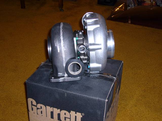
With all the work done I really didn't have anything to do during the first few winter months so I just ordered parts. The first was the most exciting being that it was the new turbo. I went through a lot of thought in deciding what I would run, looping through the common choices. TO4 (and it's many variations)? Nah. Twin S5 turbos? Nah. GT35? Nah. With the exception of using two S5 turbos as twins, all of these turbos are common and have been played out. Not at all saying they are poor choices but I'm also looking for something more unique. I took a brief look at the GT42 but that thing is huge. I knew I wanted to stick with a ball bearing turbo so I called up my friends at ATP Turbo and ordered this:
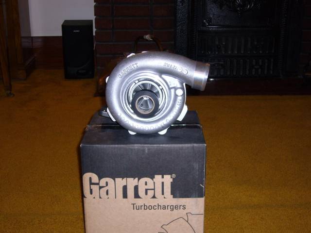
That's a GT4088R (dual ball bearing) with an 88MM compressor and 0.72 A/R housing, 77MM turbine wheel with a 1.06 hotside. The turbine inlet is divided TO4 and the outlet is a 3" v-band setup. Compressor inlet features the typical 4" "anti surge" design with a 2.5" outlet. The hotside is a bit smaller then people would typically run on a bridgeport but I'm OK with loosing a little potential at the top end of the turbo to maintain instantaneous response.
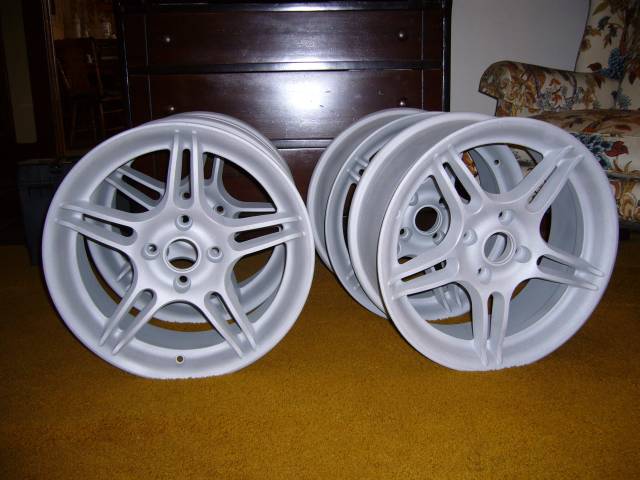
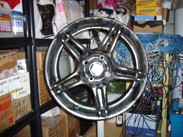
At this point it's mid February and the winter is dragging on. The winter was fairly mild with afforded more then a few days in which I could work comfortably in the garage. The first of which I spent pulling the wheels, cleaning them up, and then sending them off to the media blaster. About a week later I received my fully blasted wheels.
Here's a closeup showing the wicked-cool sight glass I had the hydraulic shop piece together for the coolant bottle. They used some opaque nylon tubing, and an assortment of fittings to put it together.
And at that point, I could drive the car. So I did. I put about 600KM on it before the winter and thoroughly enjoyed doing so. The car at that point was very evil with a tiny and responsive turbo (I couldn't stay out of boost in 5th on the highway, and just revving in neutral would spool up about 6 PSI at low throttles), virtually no interior, no radio and an insanely loud exhaust (straight pipe all the way back to two straight-through mufflers). While I drove the car I did some minor tuning and ended up with a fairly passable low-load map. I didn't want to get too much into boost as my wideband had not arrived so I only tuned up to about 6 PSI. Still, even that little amount of boost (which came on instantly at any more then 20% throttle) was plenty of fun considering I had not driven the car in years.
Only a few minor problems crept up, which I think is pretty good considering the amount of work done to the car. I need to replace my metering oil lines. The lines I rebuilt leak like hell around the nipples. So I'm just going to buy new lines from Mazda to avoid the frustration of re-rebuilding them. I also seem to have an oil leak from the front eccentric bolt that leaks about a drop or two of oil every half hour. Just enough to make a mess when slung around the engine bay. I'll need to pull the hub bolt and replace the o-ring and crush washer.
Once the winter started, the car was prepared for storage and put in the garage.
With all the work done I really didn't have anything to do during the first few winter months so I just ordered parts. The first was the most exciting being that it was the new turbo. I went through a lot of thought in deciding what I would run, looping through the common choices. TO4 (and it's many variations)? Nah. Twin S5 turbos? Nah. GT35? Nah. With the exception of using two S5 turbos as twins, all of these turbos are common and have been played out. Not at all saying they are poor choices but I'm also looking for something more unique. I took a brief look at the GT42 but that thing is huge. I knew I wanted to stick with a ball bearing turbo so I called up my friends at ATP Turbo and ordered this:
That's a GT4088R (dual ball bearing) with an 88MM compressor and 0.72 A/R housing, 77MM turbine wheel with a 1.06 hotside. The turbine inlet is divided TO4 and the outlet is a 3" v-band setup. Compressor inlet features the typical 4" "anti surge" design with a 2.5" outlet. The hotside is a bit smaller then people would typically run on a bridgeport but I'm OK with loosing a little potential at the top end of the turbo to maintain instantaneous response.
At this point it's mid February and the winter is dragging on. The winter was fairly mild with afforded more then a few days in which I could work comfortably in the garage. The first of which I spent pulling the wheels, cleaning them up, and then sending them off to the media blaster. About a week later I received my fully blasted wheels.
Thread Starter
Joined: Feb 2001
Posts: 29,798
Likes: 128
From: London, Ontario, Canada
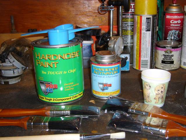
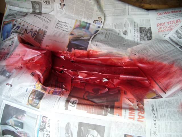
Time to paint. To paint the wheels I chose Hardnose Paint made by the POR-15 company. I've always been happy with their products and the Hardnose paint is advertised as "Too tough to chip!". It says so right on the can. Along with the paint it's important to have the right accessories. Plenty of paintbrushes, measuring cups, and puppy cups to mix paint in. Puppy cups tend to work better then other animals for this, not sure why. The Hardnose is a two part paint with an additional hardener/activator that gets mixed in when it's ready for use. Like all of the POR-15 products, Hardnose can be brushed or sprayed and will lie perfectly flat afterwards. I chose to brush since I don't have the equipment to spray safely.
Wheels are a real pain to paint due to the intricate lines and tight spaces. To make access easier I made a small adapter that fits on my engine stand. It bolts through a lug hole to the back of the wheel and makes it easy to access both sides while being able to rotate the wheel as well.
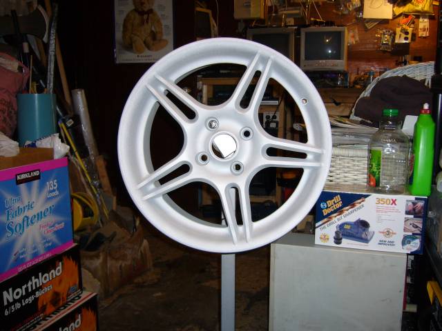
The technique I found to work best is to first lay down a very thin first coat to basically seal the metal and provide a surface for the next coat to adhere to. If you follow the instructions and lay it on thickly, it will run. As you can see from the picture, the first coat really does look awful but it gets the job done.
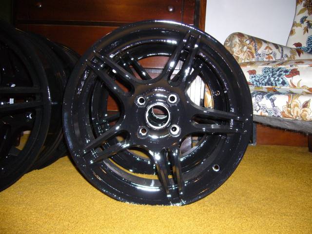
After letting the primer coat dry for about two hours, I then laid down a much thicker 2nd coat. This coat clings to the first and stays put, so even painting thickly does not produce runs or drips. Finally after the 2nd coat dries for a day, a third coat is applied to the face of each wheel to assure complete coverage on the edges.
Overall I'd say they turned out about 90% as well as I would have liked. I ended up screwing up the 1st wheel (silly me, I followed the instructions that came with the paint) and had to have it re-blasted. For being brushed, the paint is remarkably smooth but it's no powder-coat. Of course, this paint is stronger then powder coat (according to the media blaster) and it's much easier to touch up. If I had to do it again I would hire someone to spray it for me.
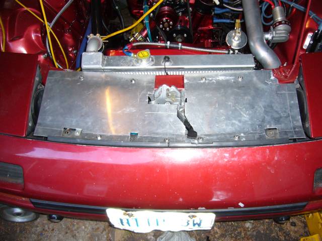
The next little fabrication task was to make radiator panels. These were made out of 2MM thick aluminum sheets after first making a cardboard template. To secure them, I welded bungs into the radiator crossmember and relay crossmember and then tapped them for M6. The panels really clean up the front of the car and provide an unobnoxious place to put some stickers.
Wheels are a real pain to paint due to the intricate lines and tight spaces. To make access easier I made a small adapter that fits on my engine stand. It bolts through a lug hole to the back of the wheel and makes it easy to access both sides while being able to rotate the wheel as well.
The technique I found to work best is to first lay down a very thin first coat to basically seal the metal and provide a surface for the next coat to adhere to. If you follow the instructions and lay it on thickly, it will run. As you can see from the picture, the first coat really does look awful but it gets the job done.
After letting the primer coat dry for about two hours, I then laid down a much thicker 2nd coat. This coat clings to the first and stays put, so even painting thickly does not produce runs or drips. Finally after the 2nd coat dries for a day, a third coat is applied to the face of each wheel to assure complete coverage on the edges.
Overall I'd say they turned out about 90% as well as I would have liked. I ended up screwing up the 1st wheel (silly me, I followed the instructions that came with the paint) and had to have it re-blasted. For being brushed, the paint is remarkably smooth but it's no powder-coat. Of course, this paint is stronger then powder coat (according to the media blaster) and it's much easier to touch up. If I had to do it again I would hire someone to spray it for me.
The next little fabrication task was to make radiator panels. These were made out of 2MM thick aluminum sheets after first making a cardboard template. To secure them, I welded bungs into the radiator crossmember and relay crossmember and then tapped them for M6. The panels really clean up the front of the car and provide an unobnoxious place to put some stickers.
Thread Starter
Joined: Feb 2001
Posts: 29,798
Likes: 128
From: London, Ontario, Canada
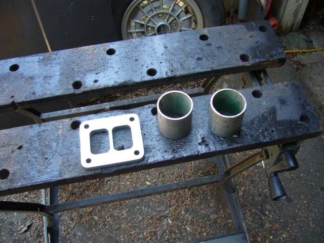
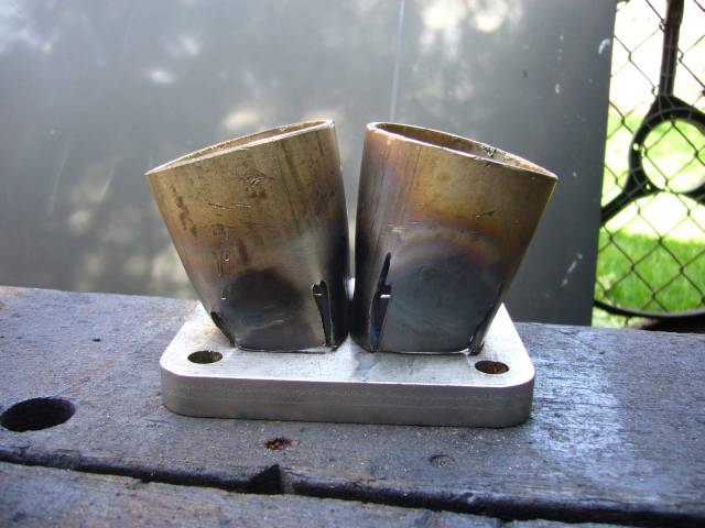
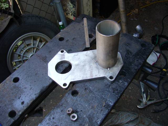
Since no one makes a manifold to fit a GT40 on a NA block with a custom intake, it's time to fabricate one!  First step is to cut two small pieces of 2" SCH10 304 stainless. I had the divided TO4 flange laser cut out of stainless.
And then those pieces need to be formed to match the rectangle ports in the flange. This involves making 4 small slits with the cutting wheel, then heating the pipe with an oxy/gas torch while crushing it in the vice. After that it takes some minor blacksmithing with a hand torch, hammer and ASO (anvil shaped object) to make the final adjustments.
I have to wonder why none of the aftermarket companies produce these parts. I would gladly have paid $50 for the set to avoid the time (and burns) it took to make these.
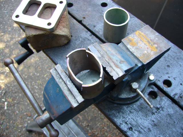
The end result is a pipe section with the end crushed to match the flange.
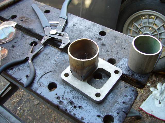
It fits well, though some minor grinding and adjustment will be required to make it perfectly. I'm planning on port matching the flange to the gasket to the turbine housing anyway (not that it really makes much of a difference).
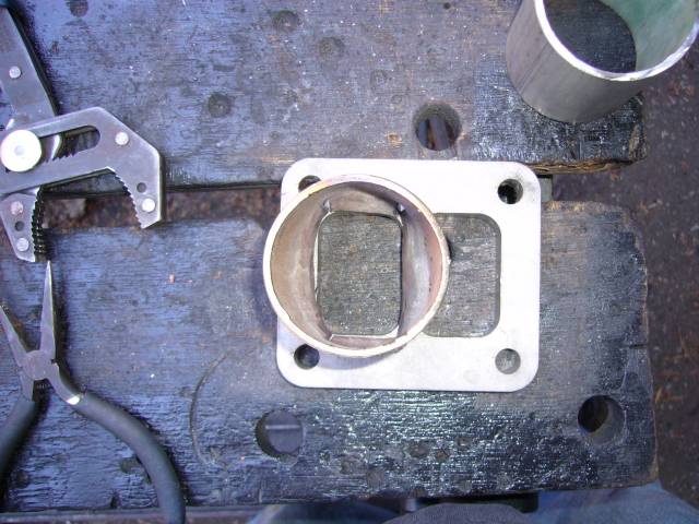
However two of them don't quite fit. The ends will need to be angled to fit flush with the flange...
First step is to cut two small pieces of 2" SCH10 304 stainless. I had the divided TO4 flange laser cut out of stainless.And then those pieces need to be formed to match the rectangle ports in the flange. This involves making 4 small slits with the cutting wheel, then heating the pipe with an oxy/gas torch while crushing it in the vice. After that it takes some minor blacksmithing with a hand torch, hammer and ASO (anvil shaped object) to make the final adjustments.
I have to wonder why none of the aftermarket companies produce these parts. I would gladly have paid $50 for the set to avoid the time (and burns) it took to make these.
The end result is a pipe section with the end crushed to match the flange.
It fits well, though some minor grinding and adjustment will be required to make it perfectly. I'm planning on port matching the flange to the gasket to the turbine housing anyway (not that it really makes much of a difference).
However two of them don't quite fit. The ends will need to be angled to fit flush with the flange...
Thread Starter
Joined: Feb 2001
Posts: 29,798
Likes: 128
From: London, Ontario, Canada
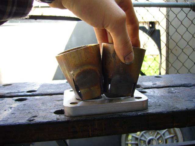
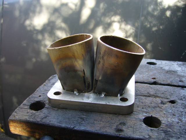
Now the fit is proper!
A few tack welds holds them in place. I used the flux core welder to tack things together as it's very convenient to run in the driveway and can tolerate less then ideal conditions. When the manifold is finished it will be brought inside and TIG welded.
While working on the flange I also repainted the radiator support since it was burned and discoloured from welding in the bungs.
The time honored method of positioning a turbo in an engine bay is to hang it with bailing wire from a 2x4. That way the position can be tweaked without the necessity of holding up a 35 LB object for hours on end. This is not a small turbo, so fitment is a challenge. Either way it's going to be higher then I want and close to the lower intake. It was either position the turbo about an inch higher then I initially wanted, or have to use a lot of short radius (and thus restrictive) els.
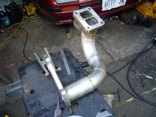
With the turbo position set and the turbine flange bolted on I could start to play with pipe fitment. After holding up various els and short scraps of straight, I had a general idea of what the rear runner was going to look like. It starts with an approximately 5" long section of straight pipe. This pipe would end up being trimmed several times as I discovered that my first mockup did not leave enough space between the manifold and frame rail to allow the flange to slip off the engine studs. Then it follows through two 45 degree else, a short spacer, and then a 90 degree el up to the flange.
A few tack welds holds them in place. I used the flux core welder to tack things together as it's very convenient to run in the driveway and can tolerate less then ideal conditions. When the manifold is finished it will be brought inside and TIG welded.
While working on the flange I also repainted the radiator support since it was burned and discoloured from welding in the bungs.
The time honored method of positioning a turbo in an engine bay is to hang it with bailing wire from a 2x4. That way the position can be tweaked without the necessity of holding up a 35 LB object for hours on end. This is not a small turbo, so fitment is a challenge. Either way it's going to be higher then I want and close to the lower intake. It was either position the turbo about an inch higher then I initially wanted, or have to use a lot of short radius (and thus restrictive) els.
With the turbo position set and the turbine flange bolted on I could start to play with pipe fitment. After holding up various els and short scraps of straight, I had a general idea of what the rear runner was going to look like. It starts with an approximately 5" long section of straight pipe. This pipe would end up being trimmed several times as I discovered that my first mockup did not leave enough space between the manifold and frame rail to allow the flange to slip off the engine studs.
Then it follows through two 45 degree else, a short spacer, and then a 90 degree el up to the flange.
Thread Starter
Joined: Feb 2001
Posts: 29,798
Likes: 128
From: London, Ontario, Canada
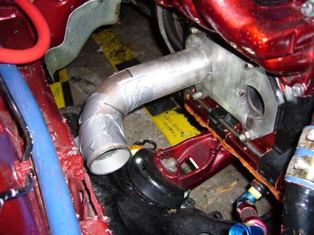
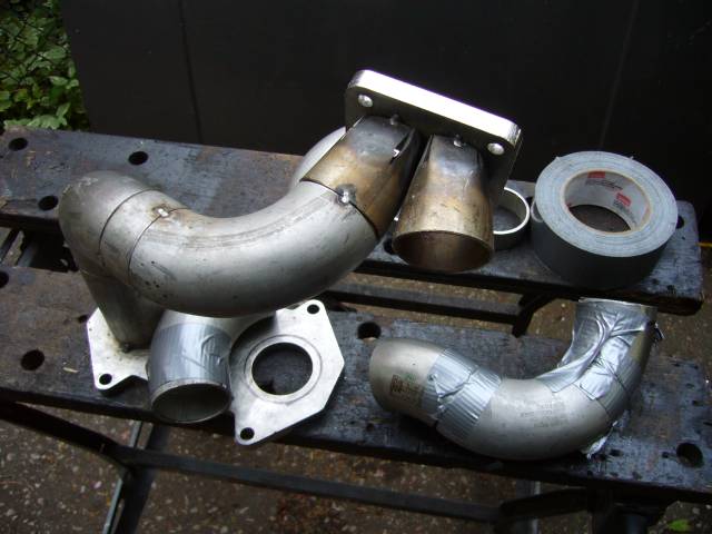
Here's the first duct-tape mockup of the rear runner. As you can see, there is virtually no room between the manifold and fender. I would have to trim some length off the straight section for clearance. When making a manifold like this, buy plenty of 90 degree and 45 degree els. Don't underestimate the usefulness of combining two 45 degree els at different angles. This mockup shows the first 45 degree el pointing to slightly down, while the next one points to the front an a little bit up. A 1" spacer of pipe is then attached to it to move the turbo forward.
Once the position of the els are finalized, the runner gets tacked into place. Generally I bring the runner out of the engine bay and then cut a "window" into the duct tape holding it together inside which I place a tack. This makes sure that the runners don't move around too much, and keeps welding debris out of the engine bay.
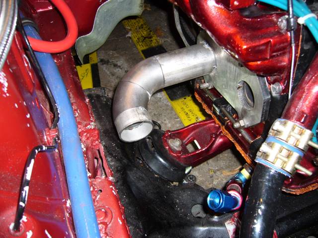
A 90 degree el was added to bring the runner up to the turbo.
And the flange was tacked into place.
I then reinstalled the manifold onto the engine to test fitment again. In order to maintain clearances the turbo sits with the rear angled a few degrees down (will make it about 10 times easier to fab a downpipe in a cramped area), the front of the compressor angles towards the engine (to provide space for outlet pipe to run past shock tower) and the entire turbo rotates out slightly towards the fender (easier access to oil drain hole).
Once the position of the els are finalized, the runner gets tacked into place. Generally I bring the runner out of the engine bay and then cut a "window" into the duct tape holding it together inside which I place a tack. This makes sure that the runners don't move around too much, and keeps welding debris out of the engine bay.
A 90 degree el was added to bring the runner up to the turbo.
And the flange was tacked into place.
I then reinstalled the manifold onto the engine to test fitment again. In order to maintain clearances the turbo sits with the rear angled a few degrees down (will make it about 10 times easier to fab a downpipe in a cramped area), the front of the compressor angles towards the engine (to provide space for outlet pipe to run past shock tower) and the entire turbo rotates out slightly towards the fender (easier access to oil drain hole).
Thread Starter
Joined: Feb 2001
Posts: 29,798
Likes: 128
From: London, Ontario, Canada
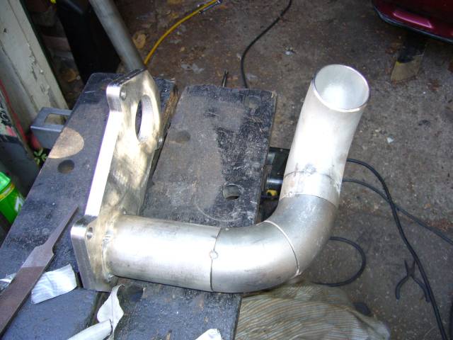
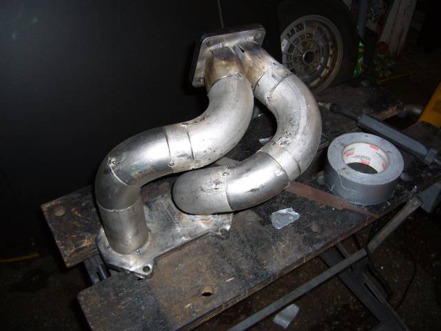
The front runner is mocked up in the same way as the rear, but this time it can be done outside of the engine bay since the first runner locates the turbine flange. Again, els and spacers were combined until the runner matched up with the engine flange and turbine flange, and did not interfere with the front runner, steering rack or engine mount. I ended up using two 45 degree els, two 90 degree els and two spacers. Almost by accident both runners turned out to be virtually the same length! Yay for me.
The front runner was then tacked into place...
...and the manifold test fitted once again. Still seems to fit.
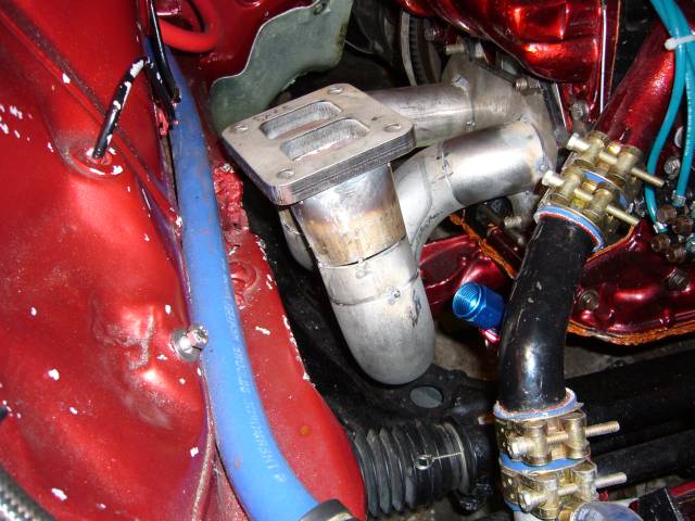
Here's a view of the turbo flange from inside the engine bay. It hovers just over the frame rail. My pipe fitment had a few gaps which is something you ideally want to avoid. Gaps allow the pipe to move during finish welding, and take effort to fill properly.
To do the finish welding I rented a Miller Maxstar 150 STH from the local welding store (Sure Arc Welding Supply). For $200 I got the welder for a month and the gas bottle, consumables (tungsten, gas, filler) extra. Pretty good deal considering that this welder retails for $1500 US, and that doesn't include the gas bottle and regulators. Overall I'm very happy with the unit and if it could do AC (it's DC only) I'd buy it in a second. For a 120V unit it's very capable of doing stick or TIG welding at up to 150A (30% duty cycle) and weighs only 18 LBs. I didn't get the optional foot control but I found that Lift-Arc was very easy to use after about a 2 minute learning curve.
The front runner was then tacked into place...
...and the manifold test fitted once again. Still seems to fit.
Here's a view of the turbo flange from inside the engine bay. It hovers just over the frame rail. My pipe fitment had a few gaps which is something you ideally want to avoid. Gaps allow the pipe to move during finish welding, and take effort to fill properly.
To do the finish welding I rented a Miller Maxstar 150 STH from the local welding store (Sure Arc Welding Supply). For $200 I got the welder for a month and the gas bottle, consumables (tungsten, gas, filler) extra. Pretty good deal considering that this welder retails for $1500 US, and that doesn't include the gas bottle and regulators. Overall I'm very happy with the unit and if it could do AC (it's DC only) I'd buy it in a second. For a 120V unit it's very capable of doing stick or TIG welding at up to 150A (30% duty cycle) and weighs only 18 LBs. I didn't get the optional foot control but I found that Lift-Arc was very easy to use after about a 2 minute learning curve.
Trending Topics
Thread Starter
Joined: Feb 2001
Posts: 29,798
Likes: 128
From: London, Ontario, Canada
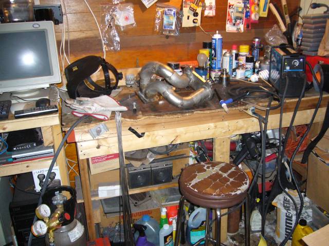
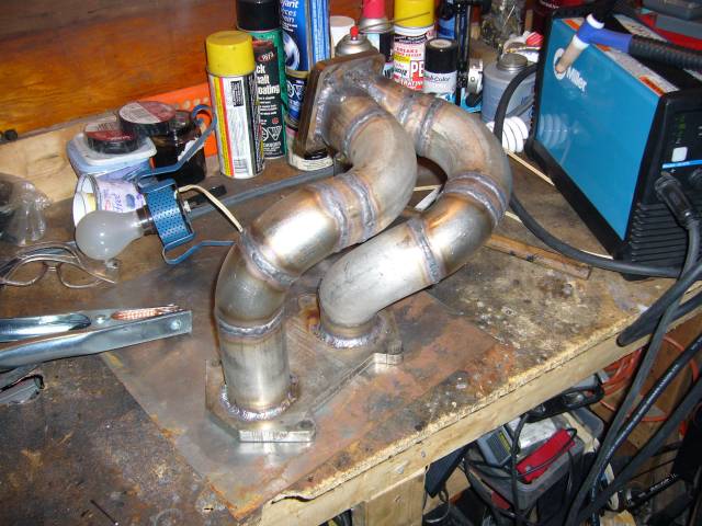
After a few hours of welding, here's the finished result. Most of the pipe was welded at 105A with great penetration and puddle control. To do the fillet welds at the flanges I cranked it up to 130A. The valley between the runners at the turbo flange was welded with some frustration by extending the tungsten about 3/4" out of the gas cup and cranking the gas flow to about 35CFH. I welded about as much as I could on each runner, then cut the tacks and welded each runner off the manifold separately. After a little frustration getting everything lined up again, the runner were tacked back into place and then fully welded.
Overall I'm happy with the manifold so far. Still need to do the wastegate runners but I can't get those installed until the downpipe is in place. This was actually a lot harder then making my intake manifold as the intake consisted of basically all 90 degree angles. The exhaust manifold has many more compound curves which can be a bit of a trick.
If I had been thinking I would have bolted both the engine flange and turbo flange to another thick piece of metal to minimize warping. Both flanges warped about 1MM during welding (no matter what you do, stainless steel loves to move during welding) so I'll have to send it to the machine shop to be flattened.
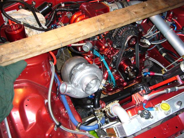
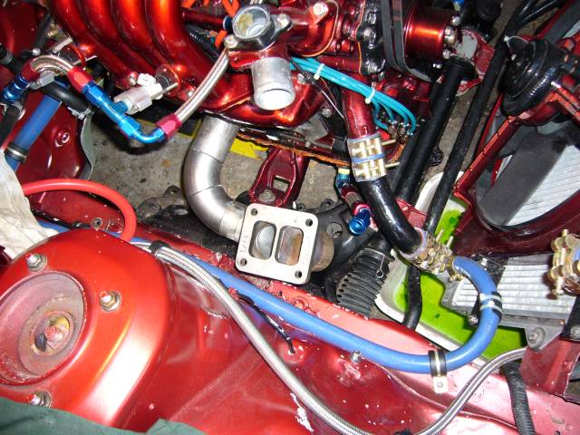
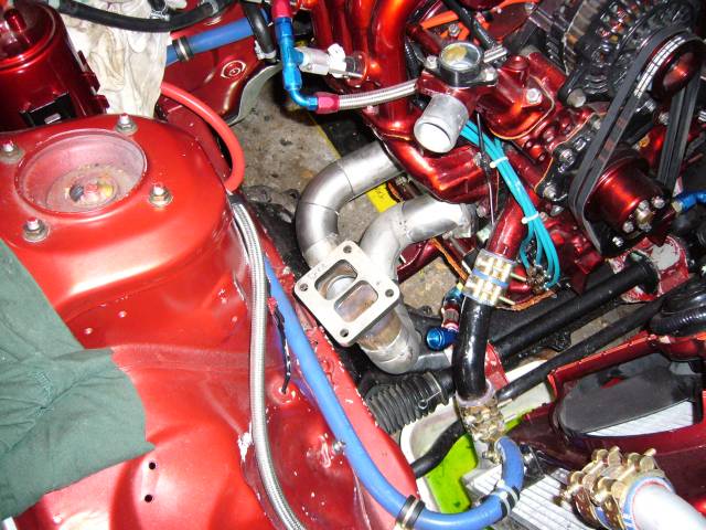
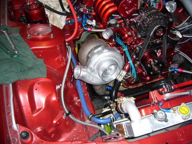
Finally the manifold can support the weight of the turbo by itself so it's time to place it in the engine bay. Beastly...There's enough room between the turbo and lower intake for plenty of heat shielding, and the oil drain will be easy to run. Going to take some thought on where to route a TID though.
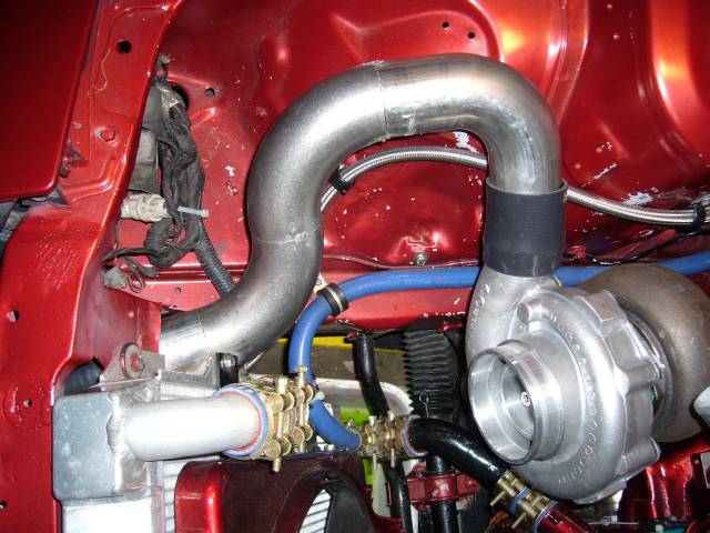
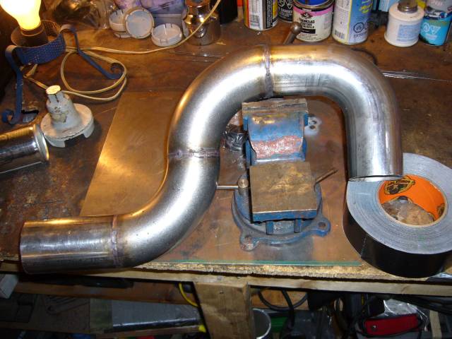
With the turbo in place I could start to deal with the plumbing around it. First task was to make a new outlet pipe. From the intercooler I used a short piece of 2.5" stainless tube, then two 90 degree weld els, then a 90 degree mandrel bend I purchased from ATP Turbo. I would have preferred to use another weld el but I ran out and figured I'd just get some 90 degree mandrel bends from ATP at the same time I was ordering some other stuff. I kind of wish that I had stuck with the els because the mandrel bend is not consistent throughout. The tubing around the bend is slightly oval in shape which took some shaping to make it fit the perfectly round els. The camera angle is looking down at the top of the rad, which is why all the angles look funny.
Here's another view of the turbo outlet pipe showing how it hugs the inner wheel well. I'm going to add a bung in this tube to provide a boost signal to the wastegate.
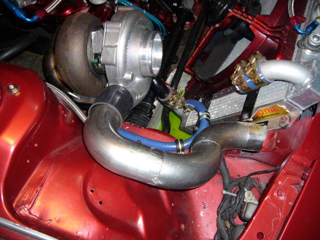
The pipe was then fully welded. I set the TIG to pulse, put the current around 50A and fusion welded most of it. Filler was required in a few areas where the weld wanted to sink too much. You can see a few dirty areas also caused by the flux core wire I used to tack. The only annoyance is that the flux and contamination in the tack cause the TIG arc to go funky as it passes over. This produces a lot of hissing and popping as the contamination burns. Cleaning with acetone helps a little but flux core welds in general are dirty.
Overall I'm happy with the manifold so far. Still need to do the wastegate runners but I can't get those installed until the downpipe is in place. This was actually a lot harder then making my intake manifold as the intake consisted of basically all 90 degree angles. The exhaust manifold has many more compound curves which can be a bit of a trick.
If I had been thinking I would have bolted both the engine flange and turbo flange to another thick piece of metal to minimize warping. Both flanges warped about 1MM during welding (no matter what you do, stainless steel loves to move during welding) so I'll have to send it to the machine shop to be flattened.
Finally the manifold can support the weight of the turbo by itself so it's time to place it in the engine bay. Beastly...There's enough room between the turbo and lower intake for plenty of heat shielding, and the oil drain will be easy to run. Going to take some thought on where to route a TID though.
With the turbo in place I could start to deal with the plumbing around it. First task was to make a new outlet pipe. From the intercooler I used a short piece of 2.5" stainless tube, then two 90 degree weld els, then a 90 degree mandrel bend I purchased from ATP Turbo. I would have preferred to use another weld el but I ran out and figured I'd just get some 90 degree mandrel bends from ATP at the same time I was ordering some other stuff. I kind of wish that I had stuck with the els because the mandrel bend is not consistent throughout. The tubing around the bend is slightly oval in shape which took some shaping to make it fit the perfectly round els. The camera angle is looking down at the top of the rad, which is why all the angles look funny.
Here's another view of the turbo outlet pipe showing how it hugs the inner wheel well. I'm going to add a bung in this tube to provide a boost signal to the wastegate.
The pipe was then fully welded. I set the TIG to pulse, put the current around 50A and fusion welded most of it. Filler was required in a few areas where the weld wanted to sink too much. You can see a few dirty areas also caused by the flux core wire I used to tack. The only annoyance is that the flux and contamination in the tack cause the TIG arc to go funky as it passes over. This produces a lot of hissing and popping as the contamination burns. Cleaning with acetone helps a little but flux core welds in general are dirty.
Thread Starter
Joined: Feb 2001
Posts: 29,798
Likes: 128
From: London, Ontario, Canada
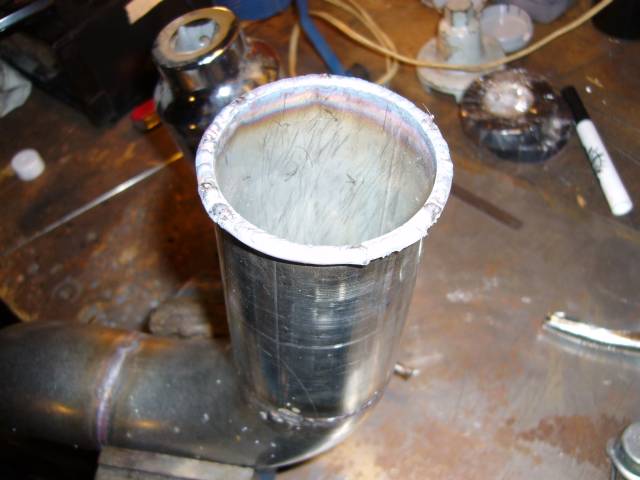
You can't see it very well in this picture as the flash kind of blew the image out but these are the beads on the end of the tube to prevent the couplers from blowing off. To create them I decided to be a total show-off so I tacked on a piece of 3/32" welding wire, used the torch to bend it around the circumference of the tube, and then welded it in place using a 1/16" filler. Needed a sharp tungsten with the welder set to about 30A. For my next trick, I'll weld the sharp edge of a razor blade to a railroad track.
And that's basically where things are now. Since I wrote this I've welded the v-band couplers onto the cat-back and made a new downpipe (with resonator). All that remains is to set up the wastegate runners and valve, figure out a TID, run oil and water to the turbo, modify the upper coolant pipe and throw on a new set of tires. Then it's back on the road for the summer, some tuning, and the interior when I feel like it.
And that's basically where things are now. Since I wrote this I've welded the v-band couplers onto the cat-back and made a new downpipe (with resonator). All that remains is to set up the wastegate runners and valve, figure out a TID, run oil and water to the turbo, modify the upper coolant pipe and throw on a new set of tires. Then it's back on the road for the summer, some tuning, and the interior when I feel like it.
Joined: Feb 2006
Posts: 2,897
Likes: 2
From: Renton/Bellevue/Seattle WA
Your crazy man! haha We had a local rx7 meeting here in yakima and it was crazy that EVERYONE knew of your "first startup movie" and how you broke out the wine 
Keep up the great work! That turbo looks awesome!
P.S. I want to see "second startup bigger turbo" video!
Keep up the great work! That turbo looks awesome!
P.S. I want to see "second startup bigger turbo" video!
Thread Starter
Joined: Feb 2001
Posts: 29,798
Likes: 128
From: London, Ontario, Canada
HA I never noticed your license plate before
Looking good Aaron, The 4088 really compliments the engine much nicer then the HT-18.
Where'd you get the coolant overlflow? I know you said the "sight glass" was custom but where'd the can come from?
Looking good Aaron, The 4088 really compliments the engine much nicer then the HT-18.
Where'd you get the coolant overlflow? I know you said the "sight glass" was custom but where'd the can come from?
Your a real inspiration to the Rx-7 community Aaron. If it not for the likes of you, I would have been out of rotary's along time ago.
Its great to see you still at it. I'll have to get your advice on how to construct a thread like this when I get my **** in gear and start my huge RX-7 project.
Its great to see you still at it. I'll have to get your advice on how to construct a thread like this when I get my **** in gear and start my huge RX-7 project.


Full Member
Joined: Apr 2007
Posts: 111
Likes: 0
From: Montreal, Canada
that is real clean. I always enjoy reading (and seeing) about your car.
You definetly arent stingy with your methods.
Fantastic!
PS, the 2nd gen project archive looks great. havent seen it since you cleaned it up.
You definetly arent stingy with your methods.
Fantastic!
PS, the 2nd gen project archive looks great. havent seen it since you cleaned it up.

looks fantastic.
I can't wait to see yours again.
You are going with a very similar turbo to me, I'm getting the GT4094R.
You get a rollcage yet? I don't remember if i saw one or not in london there.
We really should get a meet rolling for sometime in the next month.
I can't wait to see yours again.
You are going with a very similar turbo to me, I'm getting the GT4094R.
You get a rollcage yet? I don't remember if i saw one or not in london there.
We really should get a meet rolling for sometime in the next month.
Great work, great pics, and great write up. I really enjoy reading your build threads, and I'm impressed with the time and attention to detail in both the work, and the write up, Thanks for the time you put in to share your experiences.
Rotary Apprentice
Joined: Jan 2005
Posts: 2,181
Likes: 0
From: USA
looks great, the turbo looks very "at home" compared to the old one. your welds look pretty bitchin too! also, i lol'd at puppy cups. at first i though it was some term i hadn't heard of, then i looked at the cups, haha.