When you click on links to various merchants on this site and make a purchase, this can result in this site earning a commission. Affiliate programs and affiliations include, but are not limited to, the eBay Partner Network.
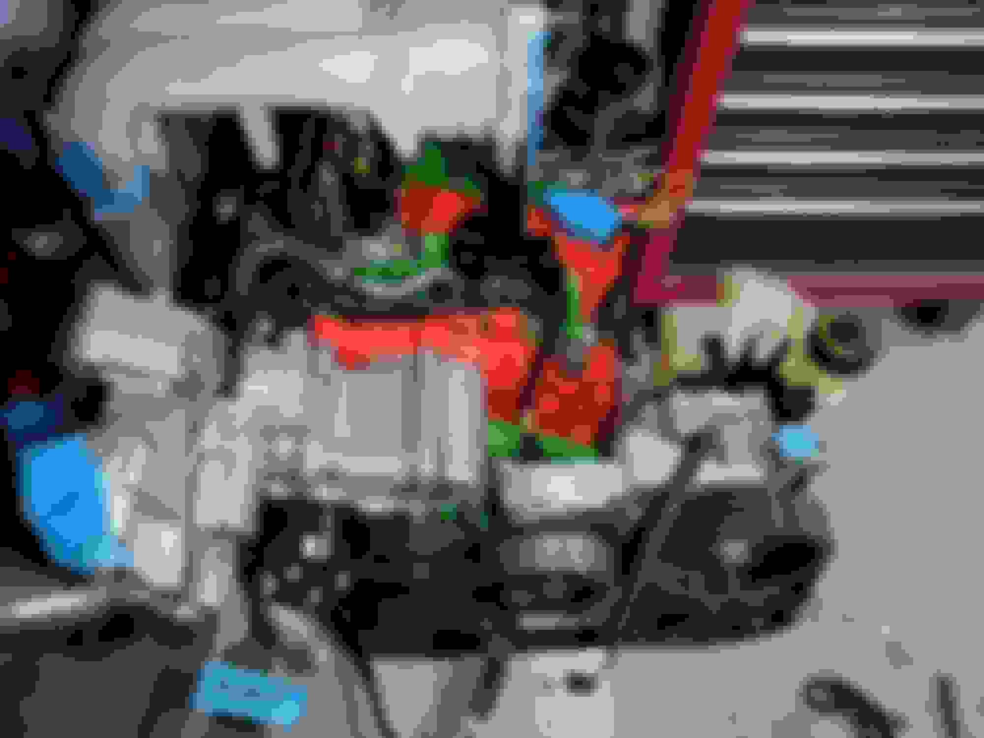
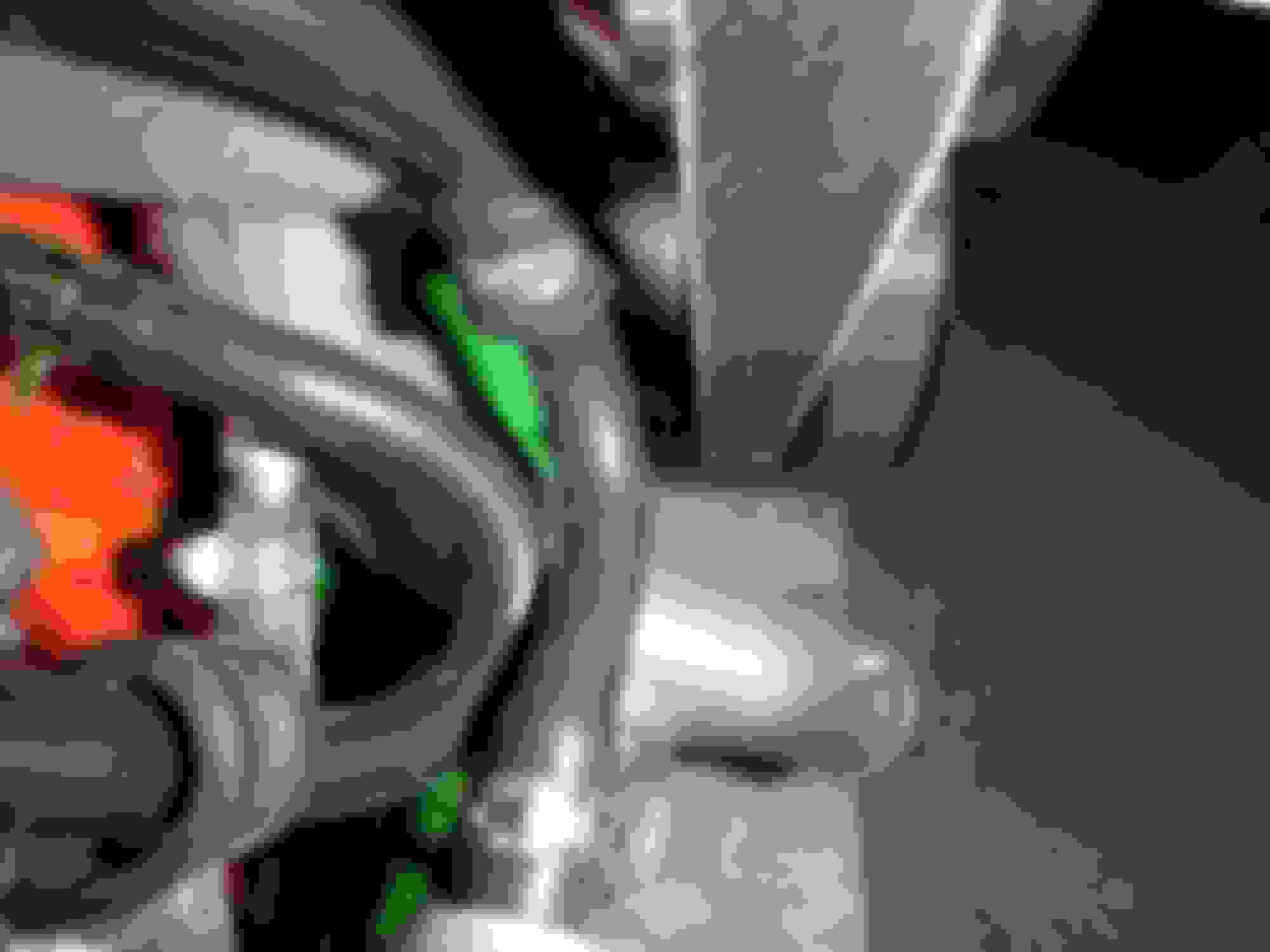
Today I installed the vacuum chamber, the pressure chamber and the oil catch can. (I also gave the chambers a nice bath)
The vacuum chamber sits below the alternator - I did not know that otherwise I would have installed it ages ago. So off comes the alternator and bracket.
I also removed the factory front tow hook at this time to paint it black. I slipped in the vacuum chamber in position and I noticed the notch for the eccentric shaft sensor harness.
Its cool Mazda did this because when the vacuum chamber is bolted down it prevents the harness from coming out.
I put back in the front engine lift bracket and to get to the outside bolt you have to leave the vacuum chamber unbolted.
I bolted down the vacuum chamber bolts and then installed the alternator.
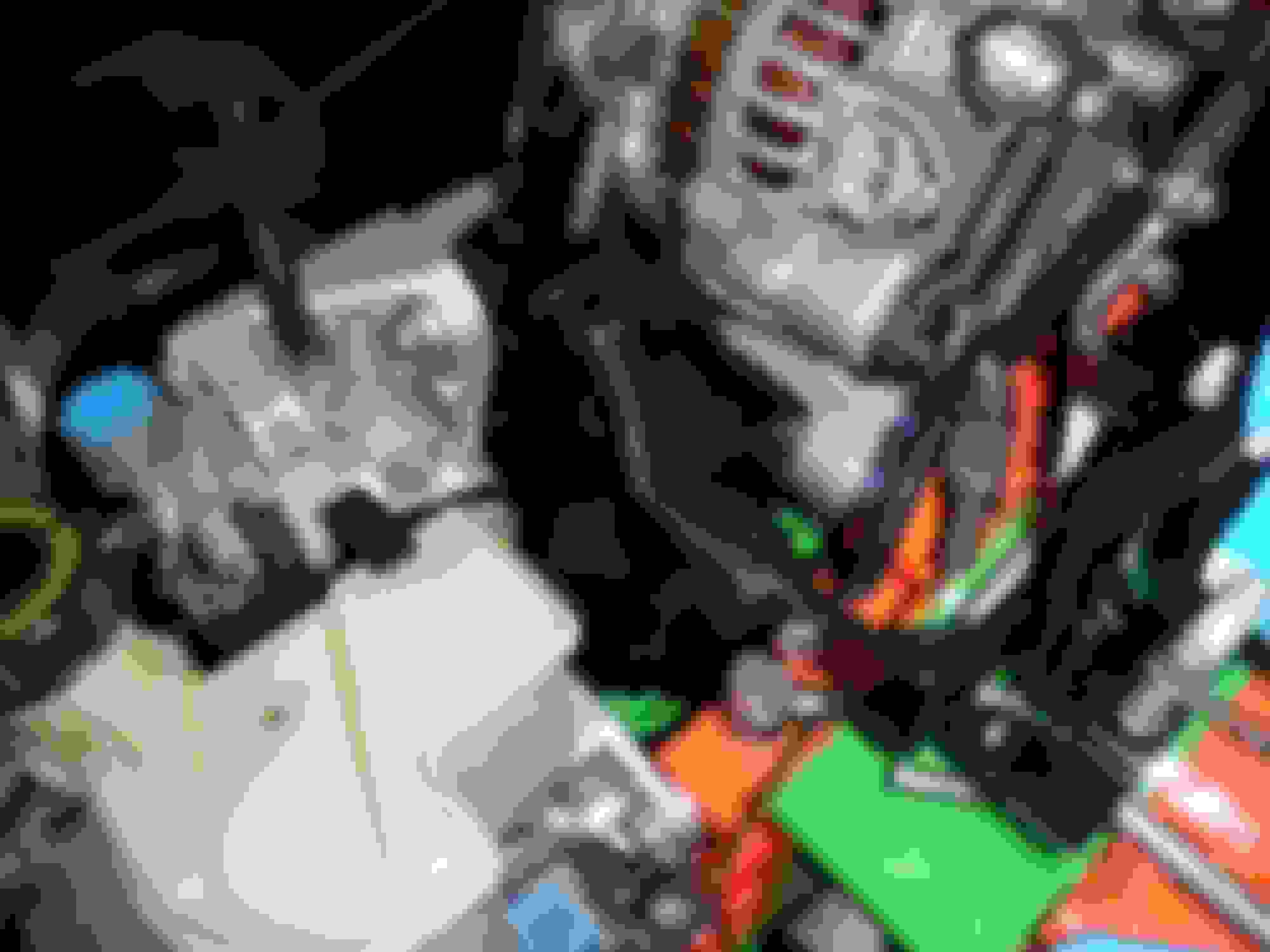
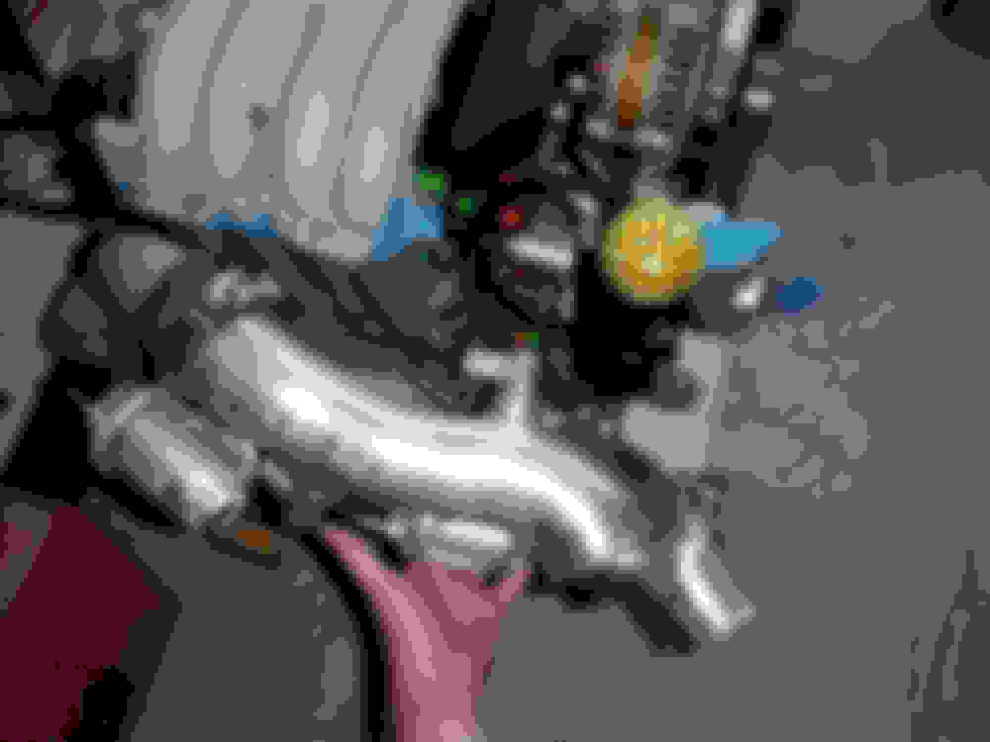
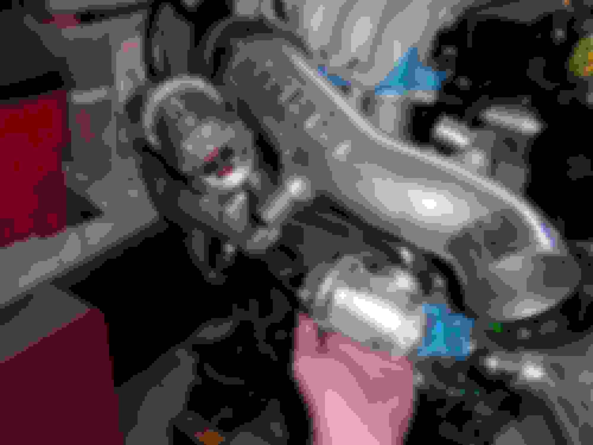
I hooked up the pressure on the original point on the UIM. I am not using the cross pipe bracket so I had to make a bracket to support the front of the pressure chamber.
I ended up making a custom oil catch can bracket that also ended up supporting the front of the pressure chamber.
Ah yes the oil catch can. It has a dipstick, a baffle on the inside and it screws apart to drain.
The hardest part was were am I going to put it so that the strut bar will not hit it ?????
I decided to put it where the air pump used to be. Putting it here allows me to re-purpose the oil vapor line running across the top of the engine.
Original is oil filler neck to pipe and then pipe to turbo intake. Im using it as oil filler neck and mid iron nipple teed together to the pipe to cross over to the oil catch can and then from the catch can back down to the turbo intake.
I had to make a bracket to hold the oil catch can so first I made an attachment point and drilled the holes to match. My taps are so rusted I had to find one the fit the original threads so I knew what to use.
Leaving the attachment piece in my drill press vice I swapped the drill bit for the tap and spun the tap by hand. This ensures that the tap is going in straight.
One I had my attachment piece I need to make my bracket. The drill press stand looks pretty close in diameter to the oil catch can so I just bent the metal around it.
I bolted the bracket to the oil air pump support bracket but I still needed a way to secure it from rotating. I found a way to kill 2 birds with 1 stone.
I made a bracket to bolt to the water pump housing that will also bolt to the front of the pressure chamber and then I welded that bracket to the oil catch can bracket.
After all tweaks and adjustments were made I cleaned it with the good ole eagle one mag and wheel cleaner, painted it black, let it dry over night and installed it the next day.
1. Oil Catch Can
2. Oil filler neck
3. More water and fuel lines
1. Oil Catch Can
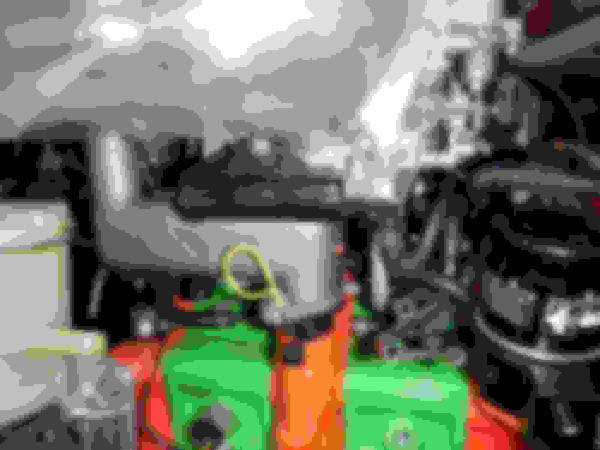
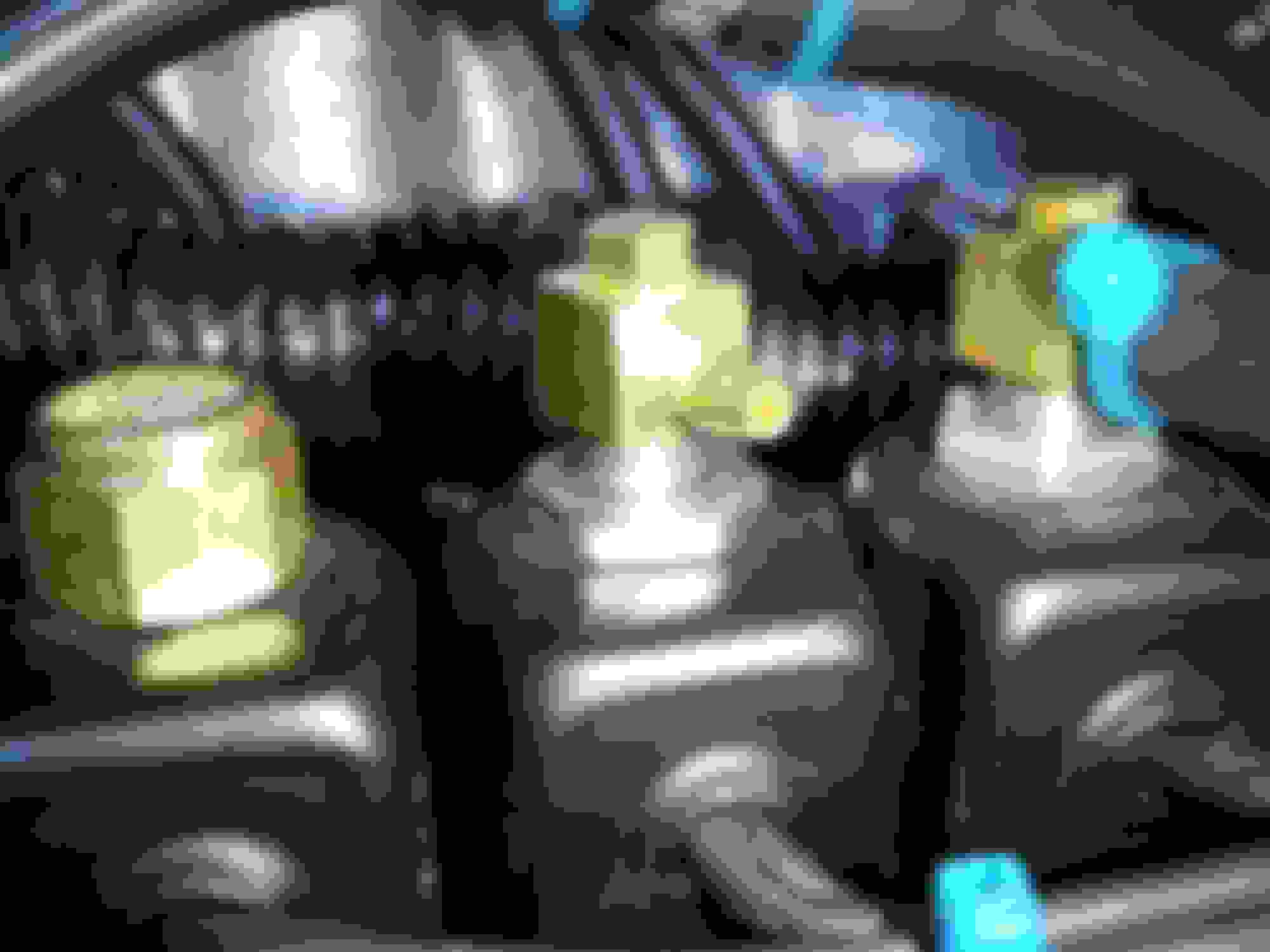
I routed the silicone hoses for the catch can like this. I hooked up the turbo side of the oil vapor pipe that crosses over the front of the engine up to the oil catch can that has the port going to the built in baffle on the inside. I routed the outlet of the catch can down to the big nipple on the pri turbo HKS intake pipe and capped the small one. I did not have to put a filter on top but I bought a little HKS looking filter years ago so I wanted to use it. I hope its not to tall - if it is Ill remove it. I was thinking that the filter would provide a little relief so the turbo would not be sucking only on the oil filler neck and center Iron causing excessive oil vapor to the pri turbo. I had to install some hose clamps to keep the hoses away from the belt.
2. Oil Filler Neck
The Xcessive oil filler neck was designed to be used with the Xcessive LIM. It came with a straight fitting and a plug. I put the plug in the upper port and put a 90 degree in the lower port to keep the hoses away from the throttle body linkage. I looped some silicone hose from the oil vapor cross over pipe on the oil filler neck side to a T-fitting and then looped that around the fuel lines to the center iron port. To keep the hose assembly from flopping all over I put some hose clamps on the existing studs used for the stock Ignition coil bracket. I also formed the T-fitting section away from the oil filler neck base. I faced the T-fitting towards the center of the engine and then ran a silicone hose around the bracket that braces the front of the UIM and back to the 90 degree on the oil filler neck. Everything clears nicely.
3. Its starting to get tight with the harness and hoses so now I have to start installing water lines, fuel lines and making sure they will be free of any obstruction. I also saw my rubber caps on the HKS intake pipes were bearly hanging on so I ordered some new silicone caps. I installed the return fuel line that will come from the FPR onto the fuel line pipe, it will have to go under the harness and loop back to the FPR - or something like that. I installed the coolant hose that goes on the back of the front coolant housing to the cross over coolant pipe the uses another 90 degree to get it to the bottom of the throttle body. The Xcessive LIM shift everything forward so I had to bend the cross over pipe to match. I took off the TB and used a screwdriver down the tube to tweak it over and placed the TB back on to verify it lined up. That last hose I installed was the hose going from the rear iron to the top of the TB. I made sure to place the clamp in the right orientation so I will have access to it later. I will be able to get to it by taking off the sec turbo intake elbow.
I like the HKS-style filter on the catch can! Nice touch!
I started looking at the pictures and I was like "that's an AST hose...." glad you caught it.
I see you have Ideal hose clamps on the water and fuel lines. Those clamps will dig into the hoses over time and degrade them. I'm not a fan of those clamps, they also don't have great clamping pressure and they strip out easily. OEM-type spring clamps or lined hose clamps are a better way to go to insure the hoses don't leak and don't get damaged over time.
Dale
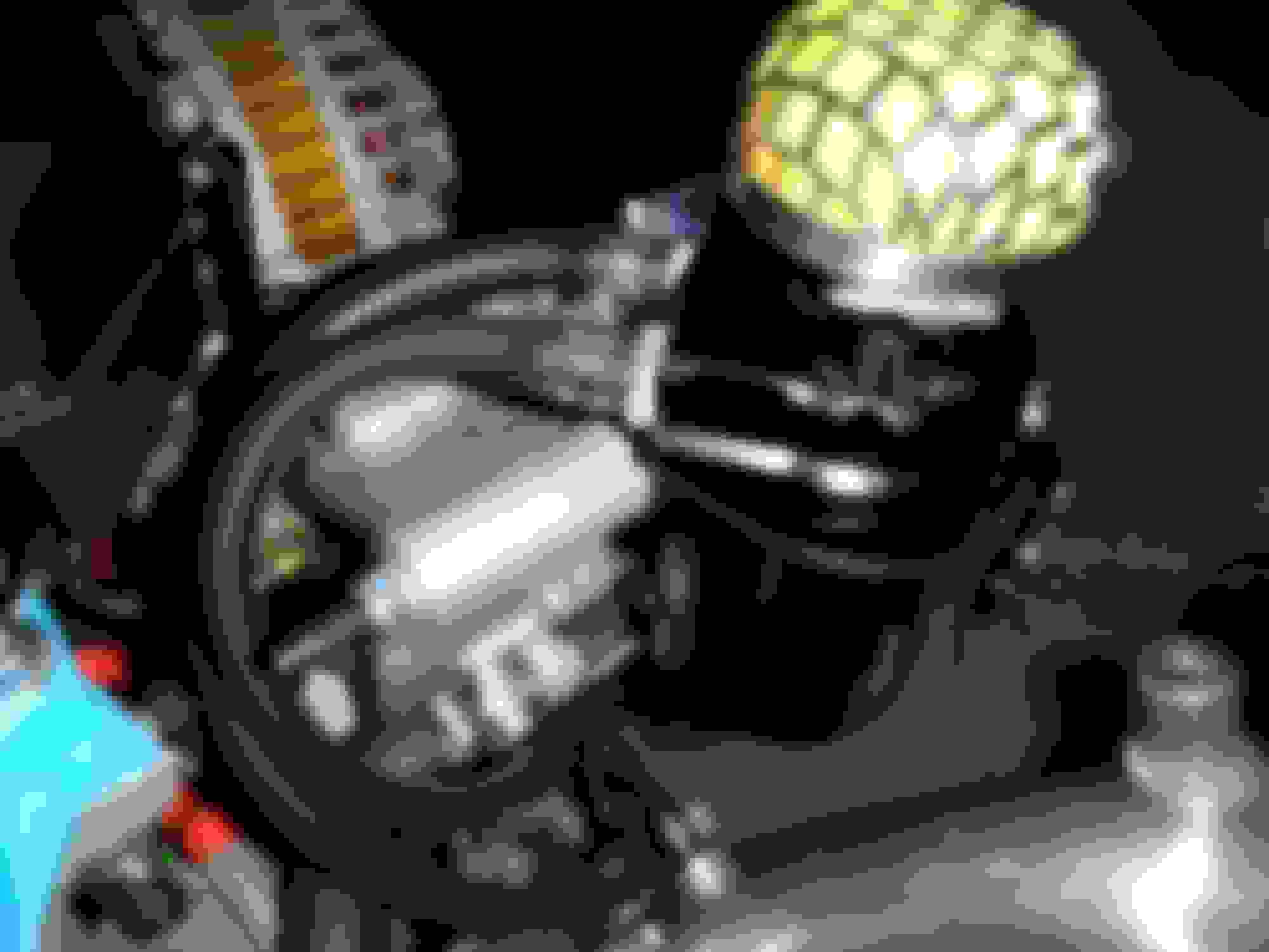
Thanks for the shout out on the little HKS type filter - I hope it clears the hood - if not I'll have to take it off.
I actually bought the right clamps and I'll change them out when I take off the UIM to do the silicone hose. I do not over tighten them and I can feel as soon as they get snug. I think that have such a bad wrap due to people tighting them to tight until the rubber buldges through the slots.
Yes - the AST hose, Ivan told me today...lol.
Fixed now. Before and after pics.
Last edited by rotaryextreme; 07-31-20 at 08:02 PM.
Part 1 - HKS BOV's, gas purge fit and aligned oil catch can
Part 2 - Updated Vacuum drawing again (for hidden UIM port)
Part 3 - So yeah - Solenoid broken port
Part 1
Im a big fan of HKS. High quality parts and we both came to life in 1973 !!!
I will be using the HKS RS Intake system and dual HKS BOV's.
The plan is to shave the ports on the intake pipes to make room for the BOV's and turbo side intercooler piping. I do not know 100% how I will fit the BOV's but I will figure it all out once the engine is in the car and I start making the V-mount.
The FD3S HKS BOV kit is designed to replace the BOV on the Y-pipe. Since I am running separate outlets to the intercooler I will use the HKS BOV Kit to replace the charge relief valve on the second turbo. For the primary turbo I will make a set-up with a Universal HKS BOV kit attached at the outlet. Im also happy the HKS BOV's have a similar glitter look !
" Yes I want all the annoying ricer noises that will come with doing this!!!!!!"
I also hooked up and test fit the gas purge chamber with the Greddy elbow - no modifications needed as the factory vacuum line had enough play in it.
The oil catch can was leaning a little bit but just enough to be annoying so I straightened that up also.
Part 2
Updated the drawing once again to reflect the newly found port under the tape. I will use this port for the MAP Sensor. The 90 degree on the back still goes to the FPR. I also wanted to tap the back of the UIM for a cleaner look on the front. I will cap the big port on the back. The 2 new ports on the back go to the Vacuum Chamber and the Gas Purge Control.
The 1/8 NPT fittings were kinda big and I wanted something smaller to fit so I found a 1/16 NPT to 5/32 barb fitting and got a 1/16 NPT tap and used a 15/64 drill to make the holes. It all came out nice.
It's amazing how this little solenoid manifold replaces that rats nest in a modified sequential set-up.
Part 3
#%^#$@%^ !!!!!!!!!!!!!!!!!!
I was putting on the vacuum line and trying to secure the clamp and I broke the brass banjo fitting that secures the block. After a panic I eventually found a replacement part at dynamco # 1293-1
But wait - there's more.... The other half was secured with an epoxy bond !!!!!!!!!!!!!!!!!
I do not have pics for everything but this is what I did. I took off the 14mm jam nut and pulled the solenoid body off and then pulled off the little plate on the bottom off as well. I unscrewed the post and as I lifted it up there was a spring loaded valve inside. I did this so I could get the stuck piece out and not damage the manifold body with debris. I used my GRAB-it tool to grind away at the brass fitting and used the other twisty one to clean it out. I used a 10-32 tap to clean the threads and put everything back together. An hour later all was good for the new parts that will arrive next week hopefully.
Day 48 update was actually about 2 days work but 2 weeks waiting on parts.
I wanted to be a little more detailed here because if this set-up works its going to be alot more helpful for anyone who wants to try the same thing.
Table of Contents
Parts update - I finally got the parts in to complete the job.
Big Picture - Pics on overview of set-up
Part 1 - Turbo Adapters
Part 2 - Pressure Chamber
Part 3 - Vacuum Chamber
Part 4 - 2nd Turbo Charge Pipe
Part 5 - Charge Relief Valve
Part 6 - Charge Control
Part 7 - Turbo Control
Part 8 - Gas Purge
Part 9 - Oil Catch Can
Parts update
I had to order some 90 degree 8mm to 4mm brass reducers for the Solenoid X and E to turbo control set-up.
I ordered 1 straight 1/4 to 1/8 reducer for the Solenoid X to H to Vacuum Chamber set-up.
I finally got the broken brass elbow in for Solenoid H and used a clear epoxy to secure it in place like the original set-up. I bought this epoxy because it came with a cool mixing tube to make sure the proper ratio was achieved.
I work with thermal vacuum chamber at work so this is where I knew about the zip ties I decided to use. Unfortunately due to the material used to make them they are a blue color but they fit in nicely and are easy to identify and they are good up to 302F. It cost about $25 shipped for a bag of 100 cable ties that are 4" long. I went this route because the fittings on the Solenoid manifold were small and the clamps I had were not holding it on right. I was also running out of clamps that did fit for places where they would work. I was also not happy with the new clamps because one broke in half on me when I opened it to slide it on the line.
quick note - cable tie specs.
Panduit� Tefzel Zip Ties Features
Material: Ethylene-tetrafluoroethylene (ETFE)
Highly Resistant To Concentrated Acids
Good Radiation Resistance Up To 100 Megarads
RoHS Compliant
Weather Resistant
UV Resistant: For indoor or outdoor use
Max Operating Temperature: 302�F (150�C)
Meets the requirements of IEEE 383
ASTM Specifications: UL83, ASTM-D2633, ASTM-D3159 Type 1
Material Specifications: Military, Federal
Material Flammability Rating: UL94V-0
Color: Aqua Blue: Denotes Tefzel Material
Ideal for use in nuclear power facilities and chemical processing plants One-piece construction for consistent performance and reliability
One-piece construction for consistent performance and reliability
Panduit� Tefzel Cable Ties are the ideal cable ties for chemical processing and nuclear power plants or any environment subject to harsh conditions as they very resilient ties. Lowest threading force of any one-piece cable tie in the industry. Curved tip is easy to pick up from flat surfaces and allows faster initial threading to speed installation. Ideal for applications requiring resistance to environmental stresses such as a chemical attack, gamma radiation, ultraviolet radiation, and extreme high and low temperatures
P.s. They have PEET 4" zipties that are good for 500F but they were $185 for 100 !!!
When searching for motor mounts - again - I came across a company called HIMNI racing and they make some cool stuff for the 7. I already have the Banzai poly mounts but I decided to go with the HIMNI instead after reading their awesome sales pitch....lol
These pics are just a real quick overview and re-cap of whats going on to make it easier to visualize all the separate sections. I have included the Solenoid Vacuum diagram, final pics of vacuum hose routing and the back of the UIM that shows where the pressure sensor, vacuum chamber, gas purge and the FPR will go. I have purposely left additional length in the silicone hoses since I do not know how the final routing will be at this time until I make the turbo to IC pipe and install the HKS intakes.
Part 1 - Turbo Adapters
These adapters are used in my twin turbo track kit that I will also be making for myself. The pri turbo outlet is from ATP turbo but I shave down the flange where the bolt holes go for our shorter studs. I also add a second Tap so that both vacuum lines can be ran to the outlet that are on the cross-over pipe.
The second turbo adapter goes to the outlet of the charge pipe and is a custom piece made for my set-up. The adapter is designed to have the aluminum outlet pipe welded to it to get it to where it needs to go. The factory oring seal is retained and it also gets tapped with the 2 vacuum lines that get Tee'd to the pri turbo outlet then go to the lines that originally went to the cross over pipe. This adapter also gets a flat bar welded to it that bolts to the UIM and LIM interface to secure it in place. On the inside we had to machine a tapered edge to prevent the 2nd turbo charge control butterfly door from rubbing against it. We could have made a thinner walled piece but since this seal is critical and the piece will be welded to we wanted to make sure it was beefy enough to take the abuse.
Since I no longer have the factory LIM I do not have the second line that is needed for the outlet adapters, I will just be using the line for the pressure chamber.
Part 2 - Pressure Chamber
On the bottom 2 port outlet side of the solenoid manifold, the line runs from the bottom of Solenoid E to the pressure chamber. Then from the pressure chamber it goes through a one way check valve that goes to both turbo outlets via a brass barb T.
Part 3 - Vacuum Chamber
This one was fun. The Main Solenoid Manifold Vacuum port is on the side of Solenoid X and had a 1/4 barb straight. I had to change that to a 90 degree 1/4 barb due to where I wanted to put the solenoid manifold. To get the side 1/4 port on Solenoid X to the top 1/8 port on Solenoid H I used a 1/4 to 1/8 reducer barb. Now that the side port on Solenoid X is reduced to 1/8 that line went to a brass 1/8 T barb that split to the top of Solenoid H and then off to another a brass 1/8 T barb that split to the Vacuum chamber and then went the other way through the check valve to the back of the UIM.
Part 4 - 2nd Turbo Charge Pipe
Another fun one. This line goes from the top of Solenoid F to the bottom of Solenoid H on the bottom 2 port outlet side of the solenoid manifold. This line get a brass 1/8 T barb that brings it to the nipple on the 2nd turbo outlet elbow with all the charge stuff on it.
Part 5 - Charge Relief Valve
On the bottom 4 port outlet side of the solenoid manifold, the line goes from Solenoid H to the Charge Relief Valve which is basically the 2nd turbo BOV.
Part 6 - Charge Control
On the bottom 4 port outlet side of the solenoid manifold, the line goes from Solenoid F to the Charge Control Actuator.
Part 7 - Turbo Control
On the bottom 4 port outlet side of the solenoid manifold, the line goes from Solenoid X to the Turbo Control Actuator. (this is the vacuum control)
On the bottom 4 port outlet side of the solenoid manifold, the line goes from Solenoid E to the Turbo Control Actuator. (this is the pressure control)
For this set-up I had to get the smaller 1/8 barb fittings on the solenoid manifold to the larger 1/4 ish nipples on the Turbo Control Actuator. I had a few ways of doing this, I could use the straight 1/8 to 1/4 reducers but then the issue would be the loop where the bottom of the turbo control actuator is, so thats why I went with the 90 degrees fittings. Then I had another option, go long on the 1/8 line or the 1/4 line. I ended up going with the 1/8 line because I felt it would be less volume of air to move for the solenoids translating into a faster response time. Now I have short 1/4 runs to the nipples on the TCA.
Part 8 - Gas Purge
Why - because I want to. I've read why its used and why its useless.
Part 9 - Oil Catch Can
Its already been covered but it seemed like a good place to add it.
The Xcessive oil filler neck was designed to be used with the Xcessive LIM. It came with a straight fitting and a plug. I put the plug in the upper port and put a 90 degree in the lower port to keep the hoses away from the throttle body linkage. I routed the silicone hose from the oil vapor cross over pipe on the oil filler neck side to a T-fitting and then routed that around the fuel lines to the center iron port. To keep the hose assembly from flopping all over I put some hose clamps on the existing studs used for the stock Ignition coil bracket. I also formed the T-fitting section away from the oil filler neck base. I faced the T-fitting towards the center of the engine and then ran a silicone hose around the bracket that braces the front of the UIM and back to the 90 degree on the oil filler neck. Everything clears nicely. For the Oil Catch Can I hooked up the turbo side of the oil vapor pipe that crosses over the front of the engine up to the oil catch can that has the port going to the built in baffle on the inside. I routed the outlet of the catch can down to the big nipple on the pri turbo HKS intake pipe and capped the small one. I did not have to put a filter on top but I bought a little HKS looking filter years ago so I wanted to use it. I hope its not to tall - if it is Ill remove it. I was thinking that the filter would provide a little relief so the turbo would not be sucking only on the oil filler neck and center Iron causing excessive oil vapor to the pri turbo. I had to install some hose clamps to keep the hoses away from the belt.
Another note is that I did buy the nice hose clamps without the slots but when I tried to take off a hose to replace a clamp it felt like it was glued on and I did not want to damage or stretch the walls so I left the current clamps in place. Yes I understand the concern of teeth chewing up the hoses but I truly believe that if you do not over tighten them - they will not cause excessive damage to the hoses. I hope this update makes things a little bit more clear to understand. Thanks for reading and please please please feel free to comment on anything or correct me where I have made any mistakes.


 07-22-20, 10:01 PM