When you click on links to various merchants on this site and make a purchase, this can result in this site earning a commission. Affiliate programs and affiliations include, but are not limited to, the eBay Partner Network.
So all in all, I was just really missing the primary fuel rail spacer, still good thing it was missing because it prompted me to do some further investigation.
I looked a little closer into the pri fuel ports and low and behold the diffusers were in there. Since I already bought new ones I wanted to pull these out for inspection - good thing I did. The rubber seals were shot !!!!!!!!!!! I used a broken bolt remover tool to get the diffusers out.
The pri rail outside rubber isolaters weren't that bad, but they are still going to be replaced.
Im using banzai racing FPD delete write up and putting 1/4 NPT with 5/16 barb on both sides of the pri fuel rail.I didnt want to ruin my pri rail paint job so I bolted it to a bracket and then held the bracket on the vice. After tapping the threads there was some roughens on the inside where the fuel injector o-ring sits. I used some 1500 grit to sand it smooth. I greased the injector o-rings and put them back into the fuel rail and now they are just chillin in place waiting on parts.
For the secondary fuel rail I ended up using 8x1.25 - 90mm to hold the rail in place. I grabbed my black AEM FPR from a stash of fuel parts I'll be selling later on. I ended up getting a 90 degree 6an female to 5/16 barb and running a fuel line to the pri rail. the other side of the sec rail will have a straight 6an to 5/16 barb going to a fuel line then upto the FPR. I bought a bunch of 6an to 5/16 barb fittings to finish this all up.
I also installed the AC back on, the tensioner and the main pulley.
Parts - I finally got my Racing Beat clutch in !!! I also got some misc wire loom sizes so I can re-wrap the harness once I have it all organized.
Day 26 update
I see I did not call this update Day 26 originally but thats what it was.
Im adding how parts were measured and some sizes.
*** These measurements are for use with the Xcessive Manufacturing LIM Only *** I dont know if it will work with the stock LIM.
CJ motorsports secondary rail with fuel pulsation damper - for 48mm injectors
34mm ID2000 with top hats
8x1.25 - 90mm with washer on top under the head of the bolt
The spacers for the rail were cut down to approx 47mm - this gives some pressure on the o-rings when bolted down.
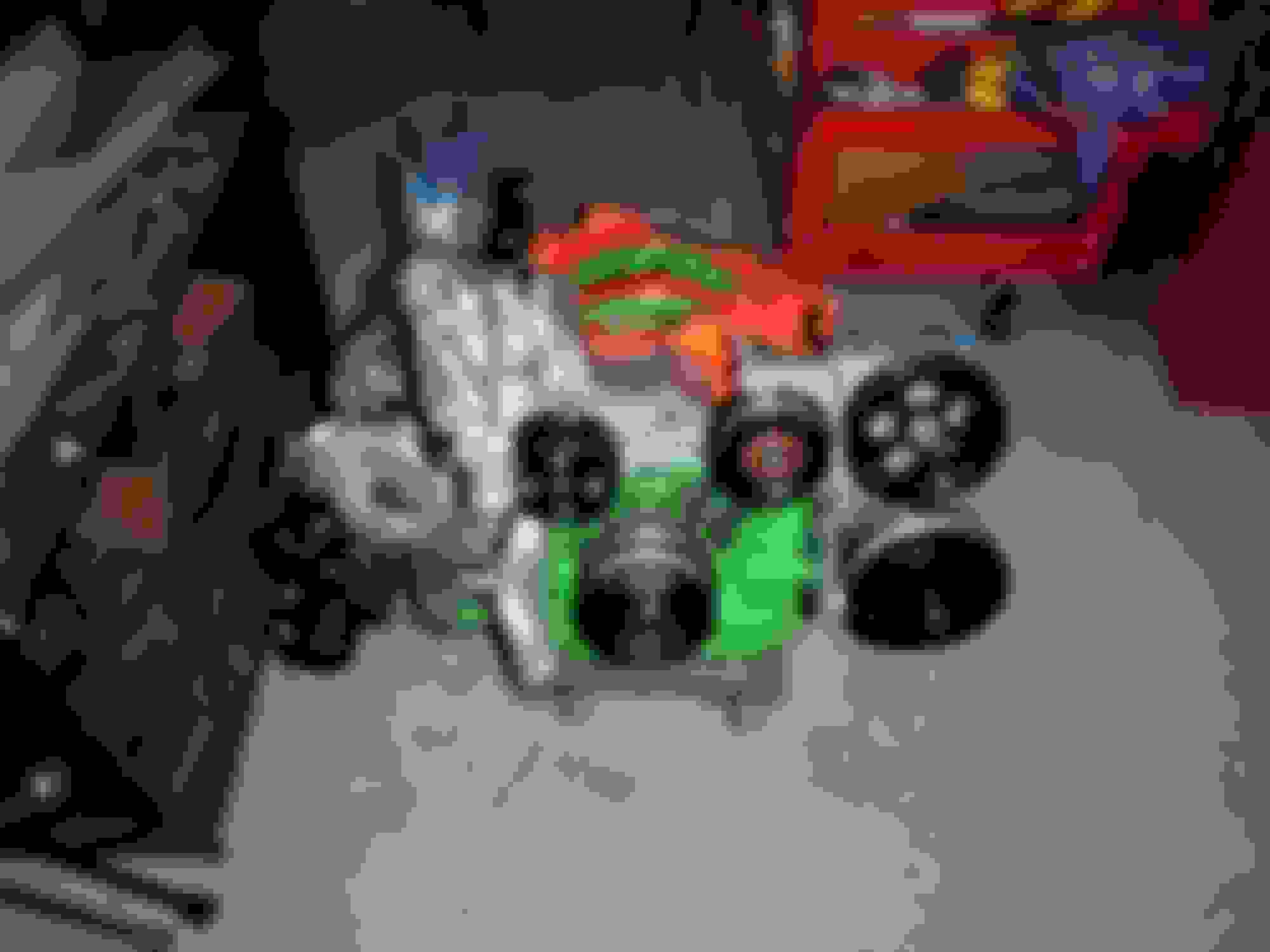
1. I made a new rolling stand for the engine.
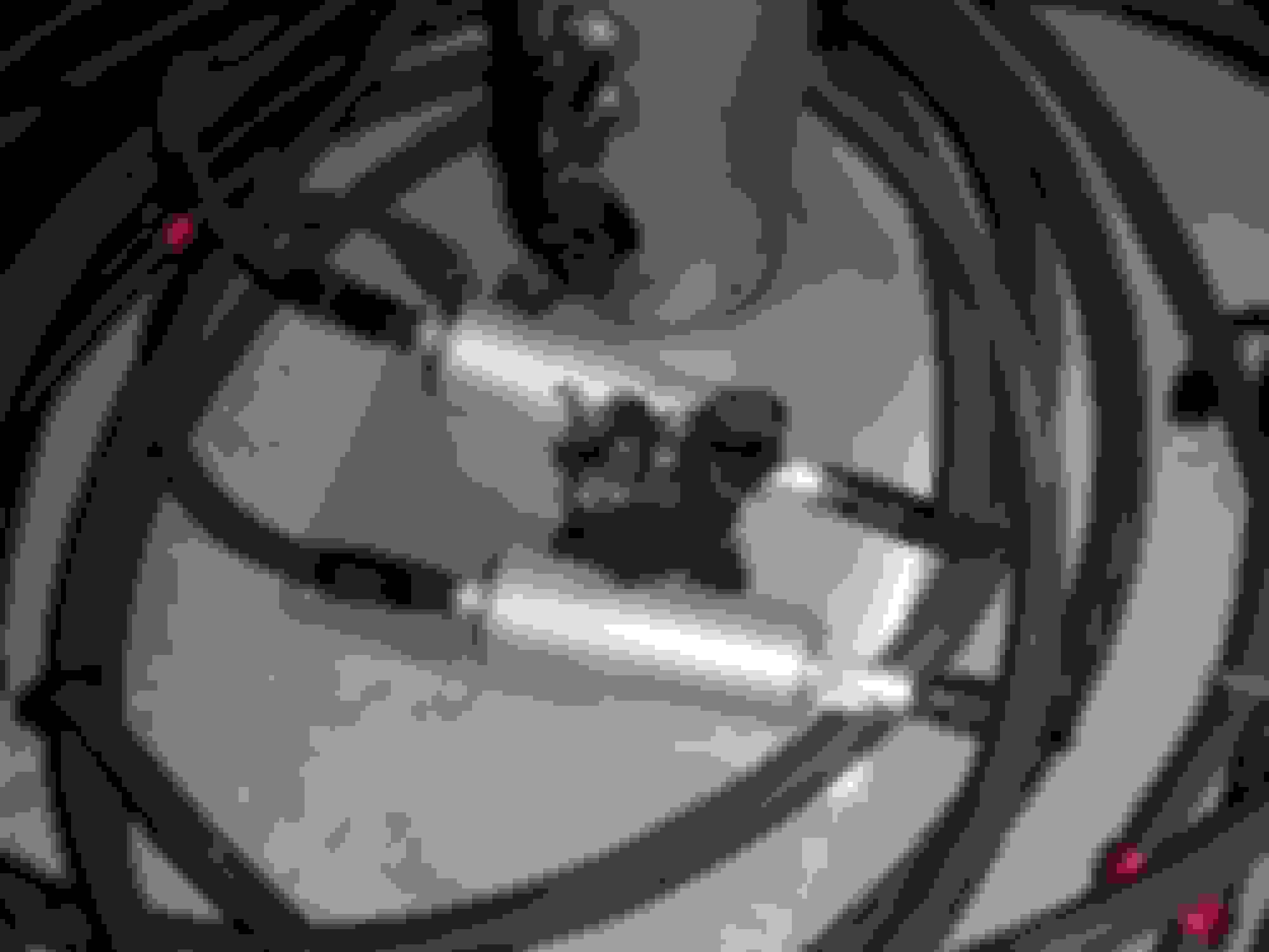
2. I installed the input and output seals on the transmission
3. I finally installed the BNR stage 1 replacement CHRA
GT28 Casting turbine wheel (better than hitachi aero)
Left hand shaft nut (no more disappearing nuts lol)
high performance 360 degree, dynamic thrust assembly(dual feed)
Dynamic, billet seal plate (less drag than stock carbon seal setup)
BNR’s drop in Billet compressor wheel upgrade (requires no modification to the compressor housing)
Dynamically balanced less than .5 gram/in2 as a rotating assembly
O ring grooved bearing housing (eliminate the silicone mess that’s normal)
1. New engine stand.
OK, so the reason I built the new engine stand is so I can work on the engine and be able to move it around easily. The smaller dolly it was on was giving me problems and I could not upgrade it with batter wheels due to the small foot print in relation to the engine. The new dolly set-up uses the same crappy wheels but now it has a larger foot print so I can install better wheels if I need to. I made a rear support for the engine mounts with metal brackets and some wood. I welded some braces between the brackets to make sure the wood would not crack under the weight of the engine. For the front I just made some stand offs out of some tubes and the go around the bolts in the front of the oil pan. The Rotary Performance rear engine lift mount worked great. I also have a oil pan brace which I didn't even know about until I did the project...so cool. I ended up swapping the turbos and it was much easier to work on the engine this time around and the dolly was easier to move around too. I noticed one engine mount was easier to move then the other and the rubber was starting crack. I ordered up some Banzai-Racing street urethane motor mounts along with the 95 glove compartment FC commander holder. Is it just me or do we just get hella messy and end up with tools everywhere during our mad scientist projects - hand to share that pic...lol
2. Transmission seals. Rear Seal. So I probably did it the wrong way but I fixed the nicks with a file. I used a small flat head screw driver to open up a gap on the rear main seal and I eventually got it out. I filed down the marks on the flange to get a smooth surface and then pressed the new rear transmission driveshaft seal back into place by hand as far as I could. There are small beads of grease inside the seal so be careful not to disturb that during the install. I did not have a socket large enough to tap the bearing in so I used a arousal glue can that had a nice deep base that would not flatten the outside of the rubber seal and it also covered about 30% of the flange. The cap was pretty strong so I tapped on it with a rubber mallet while rotating it around the metal flange on the rear seal. Its nice a flush now. Front Seal. It was a little difficult to get the front seal out but i eventually did using a pair of small pliers being very careful to not scratch the sealing surface - succeeded thankfully. I cleaned up the tube that the throw out bearing slides on and sanded it smooth. It was really gunked up. I put the front input shaft seal in, put some RTV in the bolt holes (just in case they leak) for the tube that goes over it and bolted it in place. I smeared my Valvoline all purpose grease on the throw out bearing shaft, on the inside of the throw out bearing and on the forks that go into the fork retainers on the throw out bearing and bolted the fork lever in place. I moved it a bunch of time and its silky smooth now.
I also bolted the connector bracket back in place.
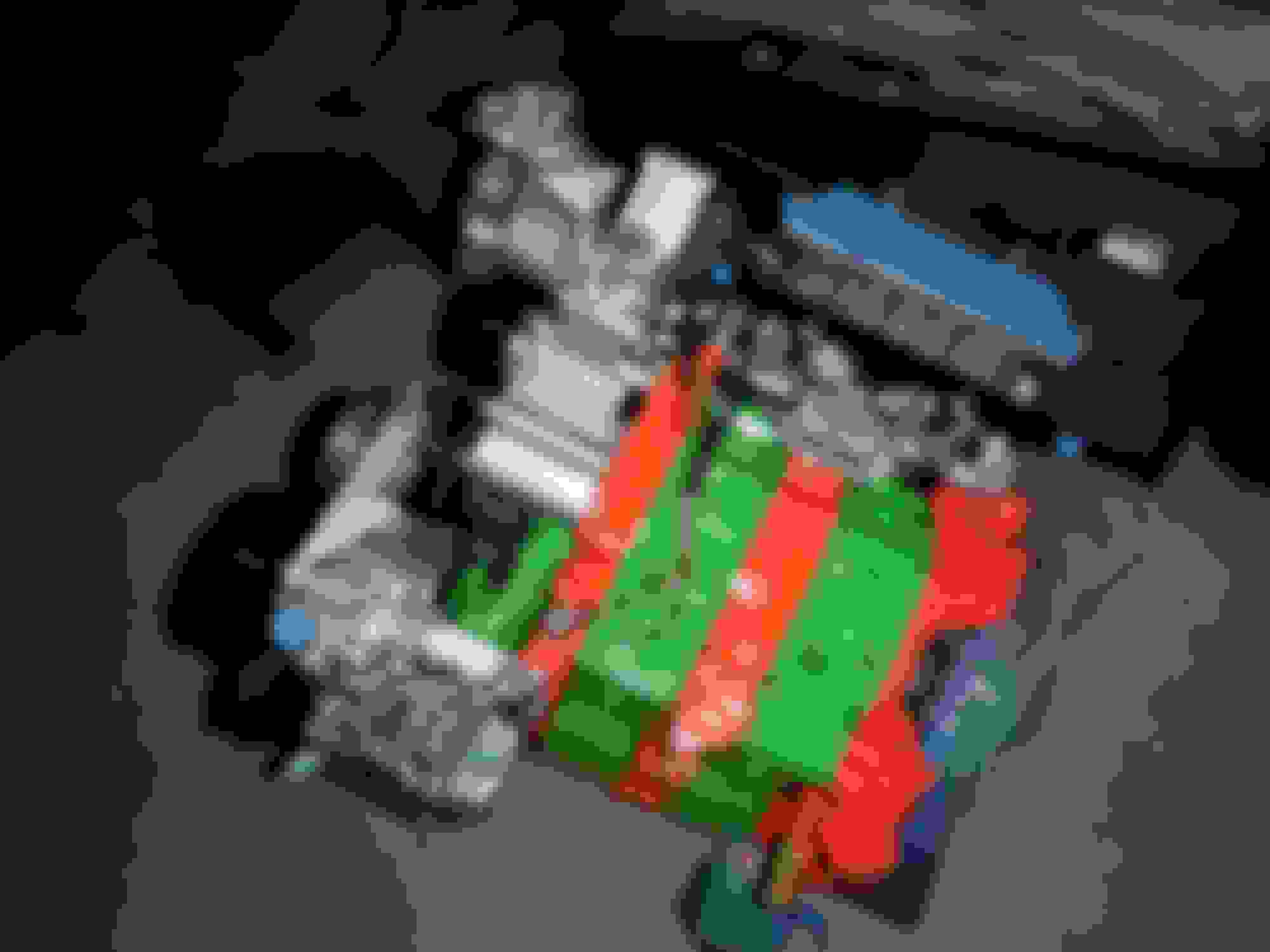
3. BNR stage 1 turbo CHRA.
During the disassembly for the turbo install I noticed the lower turbo coolant hose had a nick where it sits over the flared part of the tube and where the clamp is at is fine so I have no idea how it got there but I ordered a new hose to be safe.
I also had to break the RTV seal on the compressor housings. I used a rubber mallet and tapped the turbo outlet of the compressor housing and it broke free after a few hits on each side.
To align everything I put the new CHRA's in pace and bolted the exhaust up and mated both oil returns to the turbos and the block allowing them to rotate freely as the bolts were tightened. Once that was good then I tightened the exhaust turbine side of the CHRA's. Then I installed the compressor sides with the y-pipe and pushed the y-pipe towards the UIM until it touched. I also installed the wastegate actuators and made sure the arms were straight as possible. Then I tightened the compressor side down and the removed the y-pipe. I took the exhaust off with the turbos and tightened the remaining bolts securing the turbine and compressor sides. I reassembled everything with the new copper washers provided. I reused my oil return gaskets. Everything went back together smoothly and the STAGE 1's clear the 99 spec plastic insert just fine. Once I get the lower coolant turbo hose it'll be fully done.
Enjoy the pics.
engine stand
Last edited by rotaryextreme; 06-14-20 at 03:30 PM.
Nice! Never really saw the BNR stage 1's before, that looks good.
Any reason you didn't go with a Pineapple engine stand adapter and a regular engine stand? Though I do like making stuff yourself!
Engine looks SO good.
Dale
Thanks Dale
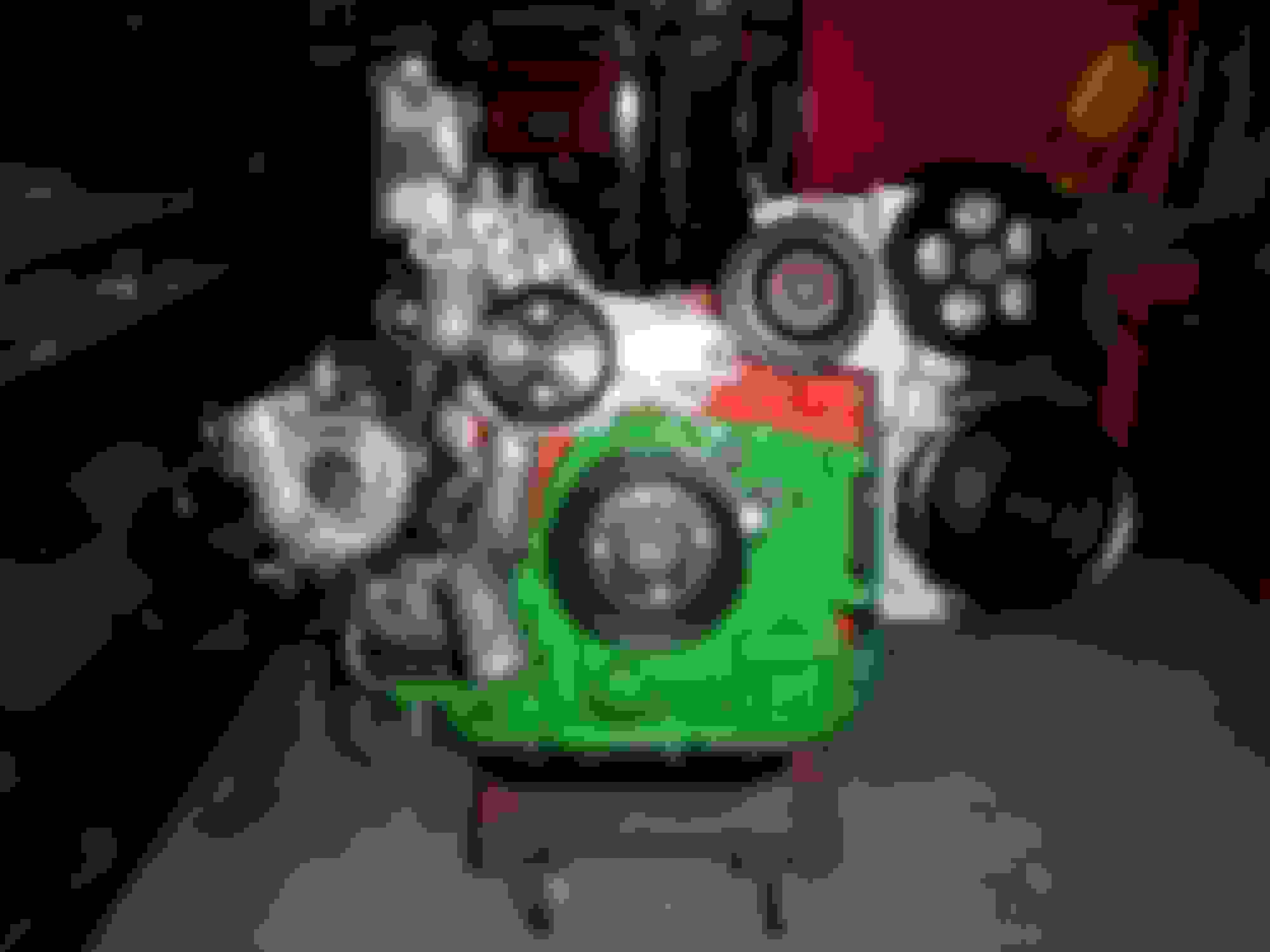
Hopefully the green and orange will stay on after start up. the silver glitter seem solid.
I wanted to mount the a/c and ps, also I dont know the effects of the engines weight long term being supported on a side load on the front iron plate. I hear stories of irons cracking while racing and I dont know what the initial cause of that weak point for it to crack. I know I could have it in pancake mode too but I really like being able to spin it around. I think the engine stand is best for building the engine - but for long term I dont think I want the weight or side load on the iron. Also the foot print of the engine stand is big and I could not pack everything into the garage when Im done for the day...lol
Eventually Im going to mate the transmission to the engine and put the down pipe on, install the engine harness and drop it in like that. Once the engine and tranys in place then I can finally paint the UIM.
soooo much to do. I realize now I was smoking a crack pipe the size of a blue whale thinking i could get everything done by November - now itll just get done when it gets done.
Just keep doing some here, some there, and eventually you'll have it all done.
I'm working with a guy here in town who has had a short block on an engine stand adapter/engine stand for 20 years (no joke) and has moved the engine across states multiple times (military move) and it's totally fine. I've also had engines on the stand while I'm breaking loose the front pulley bolt with zero problems. I always use 3 fasteners to connect the engine to the stand.
Yeah, you can't fit the AC pump/PS pump on the stand, I just have that ready and attach when it's on the chain ready to go back in the car.
Anyhow, keep up the good work, enjoying these pictures
Nice job but the worm gear hose clamps on the turbo coolant hose makes me cringe. That hose failed at the worm clamps from the affect of expansion and contract of heat cycles on the dissimilar materials. That specific hose is what led me to research hose clamps.
That transmission looks minty! I just finished rebuilding mine a little while back. Just a note on the output shaft seal ~ the little hole on the outer most ring is supposed to face down. This allows air to not be trapped when inserting the driveshaft. With it in that position you have it, it will hold moisture/water accumulation over time. Best bet now is to just put a dab of rtv on it rather than trying to reindex it.
~ GW
PS ~ I am still rocking the toe links and trailing arms I picked up from you years back. Holding up nicely.
Just keep doing some here, some there, and eventually you'll have it all done.
I'm working with a guy here in town who has had a short block on an engine stand adapter/engine stand for 20 years (no joke) and has moved the engine across states multiple times (military move) and it's totally fine. I've also had engines on the stand while I'm breaking loose the front pulley bolt with zero problems. I always use 3 fasteners to connect the engine to the stand.
Yeah, you can't fit the AC pump/PS pump on the stand, I just have that ready and attach when it's on the chain ready to go back in the car.
Anyhow, keep up the good work, enjoying these pictures
Dale
Thanks Dale!!, makes me feel safer about the engine, but yes 2 main reasons were I wanted to mount a/c and ps and eventually mount the transmission and install as one unit.
Originally Posted by gracer7-rx7
Nice job but the worm gear hose clamps on the turbo coolant hose makes me cringe. That hose failed at the worm clamps from the affect of expansion and contract of heat cycles on the dissimilar materials. That specific hose is what led me to research hose clamps.
I know, Im hearing alot about it and I did have other clamps but I could squeeze them open with my fingers, I am just tightening the worm clamps just until i feel it get snug. I must have ripped it pulling it off one of the 3 times Ive played with the turbos. Im just glad I saw it. (can you send me a link to some clamps you would recommend.
Originally Posted by gdub29e
That transmission looks minty! I just finished rebuilding mine a little while back. Just a note on the output shaft seal ~ the little hole on the outer most ring is supposed to face down. This allows air to not be trapped when inserting the driveshaft. With it in that position you have it, it will hold moisture/water accumulation over time. Best bet now is to just put a dab of rtv on it rather than trying to reindex it.
~ GW
PS ~ I am still rocking the toe links and trailing arms I picked up from you years back. Holding up nicely.
Cool right on on the Toe and Trail!!
Thank you so much for the note on the transmission seal !!!!. I really really dont want to pull it out and warp it so Ill put some rtv on the hole on top and drill a small hole on the bottom then maybe use a solder iron to make the hole a little bigger. I would be scared the drill bit will some how catch or tear the rubber.
Thank you all so much for the tips and teaching me the ins and outs of these things. Im just a shade tree mechanic at heart !!!
Don’t feel to bad, I installed mine with it facing up by accident. No way I was pulling that out again. I did just as you described, and used a soldering iron to melt a little hole at the bottom.
Don�t feel to bad, I installed mine with it facing up by accident. No way I was pulling that out again. I did just as you described, and used a soldering iron to melt a little hole at the bottom.
Done, so glad I used a soldering iron - Thanks again for the tip !!!!
Last edited by rotaryextreme; 06-16-20 at 09:00 PM.
I was thinking of hooking it up and running simplified rats nest with boost control version one. My Greddy profec B will control the wastegate but ill still use the stock solenoid for the turbo pre-control with pfc.
Another question is about the pill in the line for the pre control - or should I used a manual control to set the restriction to fine tune the transition.
what do you guys think about this ??
Last edited by rotaryextreme; 06-28-20 at 03:43 PM.
I've been running both PC and WG teed on my Apex AVC-R for 10-15 years now. Works flawlessly.
I don't really see a good reason to have a separate control for the PC. Also, the big thing here is having an ECU that will let you play with the transmission point. Lowering the transition point on the PowerFC makes a HUGE difference. I have zero boost drop. If I want 12psi, I have 12psi all the way through the power band, no dips. Same for 14psi. Also simplifies the plumbing.
Also, I typically pull out the stock hose barb on the turbos that's on the compressor outlet. It's just pressure fit/glued in. Remove in and run a 1/8" NPT tap and put a brass barb fitting in there. Have that feed the input of the boost controller then have the output of the BC teed into the wastegate and PC cans. Cap the nipple pointing to the right on each can and you're good. Eliminates a lot of plumbing.
Dale
Thanks Dale,
So the Transition point - Then its up to the charge relief? - Is that what the PFC will be controlling for the "transition point"
Ben
Last edited by rotaryextreme; 06-29-20 at 03:44 PM.
The thing that sets the transition is the turbo control door opening and the charge control valve opening. It's all staged to make it smoother but that's generally it. You also have charge relief which is shut when charge control opens.
Basically your proposed diagram there looks on point. There's also a nipple on the Y-pipe that points down, it goes to a larger (6mm) nipple on the lower intake manifold. You need to leave that in place, that helps fuel atomization. There's been some discussion lately of people that hooked that up wrong or blocked it off and it made a substantial difference in idle and low speed driving.
Dale
Dale,
-Just to confirm on whats left for the PFC to control is the transition for the turbo control in the main manifold bolted to the engine and the charge relief (2nd BOV in recirc) and Charge Control (butterfly) both are on the outlet of the second turbo which is the back half of the y-pipe. The BOV on the front part of the Y-pipe is for your standard vent to air BOV. I also wanted to note that the charge relief actually sits behind the butterfly on the second turbo outlet to vent the air when the butterfly closes.
-Boost controller now controls wastegate and turbo PRE-control.
Thanks for the explanation on that.
As far as the other 6mm hose I have the covered in my twin track kit I make for my customers.
I will be making this kit for myself except with black silicon and HKS intakes and hopefully black HKS bovs (yes I want to run one possibly in re-circ for the charge relief on the 2nd turbo outlet.
I will not be running a y-pipe-but I have tapped in the line your talking about - I have provided a link to how it looks on the car and another link showing the pieces of the kit.
**** Mods-I am not pitching a sale..Im just sharing what Im doing for myself. **** p.s. I am also not making anymore vm kits for a while.
Yep, charge relief (the blowoff valve in the back) and charge control - the butterfly valve in the Y-pipe that prevents the primary turbo's boost from going into the secondary turbo during pre-staging.
3 things to control with 4 solenoids. The turbo control uses vacuum and boost to move so it moves quickly, one solenoids for the vacuum side and one for the boost side.
Dale
Thanks Dale - I have updated my previous post with this info and also notes for myself.
Last edited by rotaryextreme; 07-01-20 at 02:38 PM.
This is not the video Im building the car for, but its another video I did for fun.
and
Final Vacuum drawing I hope, I only have 2 ports on the back - I have a newer designed UIM, also I do not have the nipple on the xcessive LIM so I hope itll run good without that fuel atomization line.
Last edited by rotaryextreme; 07-04-20 at 09:43 AM.


 06-11-20, 02:22 PM