When you click on links to various merchants on this site and make a purchase, this can result in this site earning a commission. Affiliate programs and affiliations include, but are not limited to, the eBay Partner Network.
So basically this is what I'll have.
No emissions
No oil control = premix
Boost controller replaces solenoids for wastegate and turbo pre-control
Oil filler neck has two ports.
1. pcv with 1 way to uim
2. from oil filler neck to pri turbo suction tube
And I added a new update because my turbos will have separate outlets so I will tee each together and the go to the pressure chamber which is what the y-pipe did.
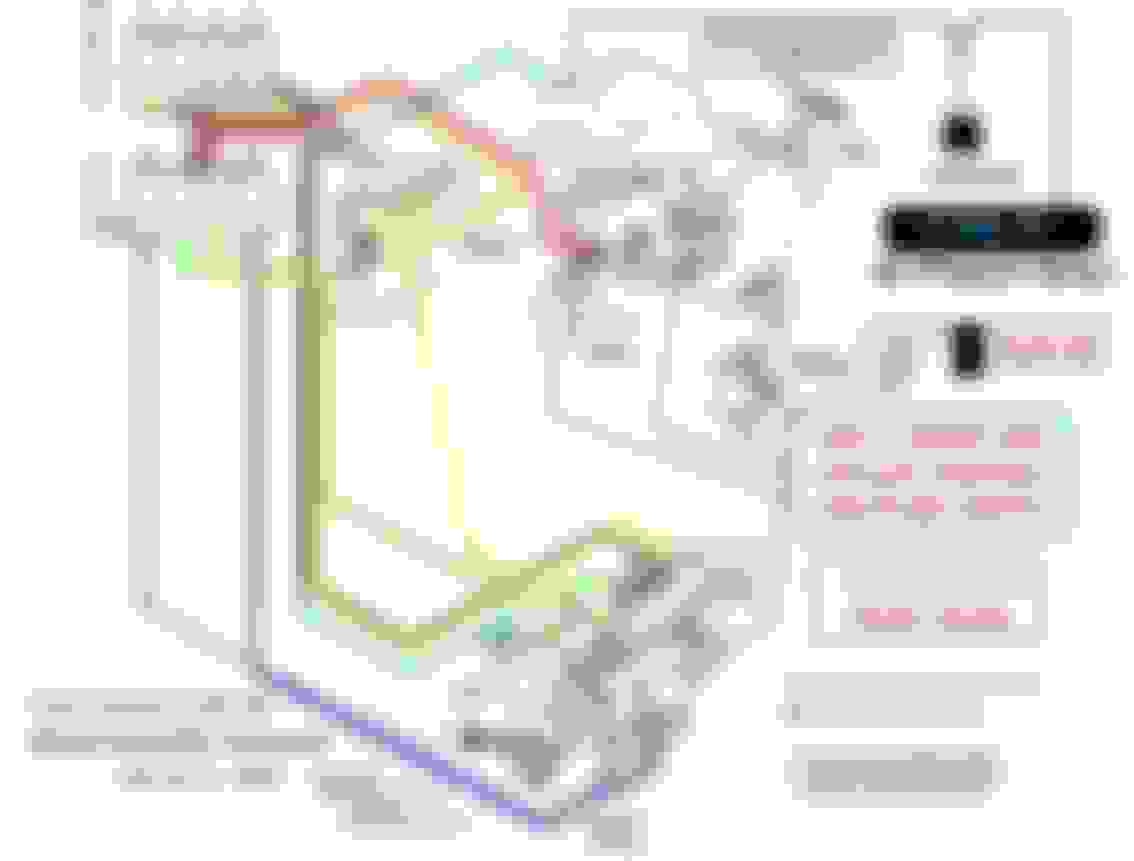
Im also adding some reference drawings I found helpful to me modify my harness for my use.
Block (1)
A1-03 � Starter Cut Relay
F1-01 � Hazard / Flasher Unit
X-09 � Connector Between Front & Air Bag
X-03 � Ignition Switch
X-04 � Combination Switch
J4-04 � Theft-Deterrent Control System - Option Switch
X-08 � Connector Between Front & Dash
X-10 � Connector Between Front & Rear
J4-01 - CPU #2
A1-04 - Starter Interlock Switch
JB-04 - Drivers Side Joint Box - Front Harness
JB-06 - Drivers Side Joint Box - Front Harness
X-06 � Connector Between Front & Instrument Panel
0-04 - LF ABS Wheel Speed Sensor
B1-09 � Igniter
B1-10 � AC Condenser
B1-05 - Fuel Pump Resistor
Q-04 � Cruise Control Actuator
C1-11 � Brake Fluid Level Sensor
Block (2)
X-02 � Relay Fuse Box
X-01 � Main Fuse Block
X-12 � Connector Between Front & Engine
E3-02 � LH Front Turn Signal
E1-03 � LH Retractable Headlight Actuator
F3-05 � LH Horn
E1-06 � LH Headlight
E1-11 � Foglight harness
E3-04 � LH Front Side Marker Light
D1-02 � Washer Motor
G-04 � A/C Refrigerant Pressure Switch
JC-01 - LH Joint Connector / Ground
Block (3)
B2-02 � Cooling Fan Relay #2
B2-01 � Cooling Fan Relay #1
E3-03 � RH Front Turn Signal
B2-03 � Cooling Fan Relay #3
E1-04 � RH Retractable Headlight Actuator
B2-04 � Cooling Fan Relay #4
J4-05 - Theft-Deterrent Control System - Hood Switch
B2-06 � Cooling Fan Motor #2
B2-05 � Cooling Fan Motor #1
F3-06 � RH Horn
JC-02 - RH Joint Connector / Ground
E1-07 � RH Headlight
E3-05 - RH Front Side Marker Light
Block (4)
B1-01 � ECU #1
X-05 � Connector Between Front & Emission
X-07 � Connector Between Front & Dash
X-13 � Connector Between Front & Floor
0-03 � ABS Hydraulic Unit
0-05 - RF ABS Wheel Speed Sensor
0-02 � ABS Hydraulic Unit
D1-01 � Wiper Motor
Last edited by rotaryextreme; 07-06-20 at 06:36 PM.
Reason: misspelled
1. Greddy Profec B throw back - sitting in a box for 20 years and new its finally going to get used.
I kind of did an un-boxing - It was packed really nice and came Japanese and English instructions plus a mail in guarantee !!!
It has a very good drawing on how to set it up, and over boost switches on the back - now I know why they say this BC is good for the 3rd gen.
There is alot of cool stuff that came with it and the 3 things I like most are the TRUST labeled vacuum lines, (ill use for the small lines for the FPR and BC, and the big lines for the BC solenoid and the pre turbo and wastegate actuators), the Greddy pick to switch the switches on the back of the BC and the 6mm nipple - which I took DaleClark's advice and pilled out the fitting on the pri turbo compressor and with a vacuum cleaner and a tap as was good - now I have a nipple there.
2. Solenoid rack removed - Im keeping the brackets to reuse the support for the UIM and PS pup reservoir (i think) also for the coolant and fuel hard lines. I will be relocating the IGN coils.
3. Engine Harness - everything is pulled back that Im not using. Things I need to fix on the harness; I nicked a wire while removing the harness wrap, found 2 main ground wires damaged, thermo fan switch connector fell of the wire, other exposed wires at some connectors and a bunch of tie-backs on wires I cut to get other wires Im not using out of the way. There is also a bracket towards the back and I forgot where it bolts to, can you guys help me?? Its circled in red on the last pic.
The "where does this bracket go" that's on the firewall side of the LIM. I think it goes over the studs where the ACV return pipe bolts to. It's pretty obvious when you lay it on the engine.
Ain't nothing like new in the box JDM electronics!
On the PCV system, Mazda got rid of the PCV valve in '95 going to the upper intake manifold. They just capped the UIM and the sideways-pointing nipple on the oil fill neck and just left the down-pointing nipple going to the nipple on the primary turbo inlet. I run a small catch can plumbed into both nipples, it's a Jaz catch can for karts and has a filter on the top to let it breathe. For street driving I've had zero problems with it.
For the FPR I would make sure it's going to the stock feed nipple for the vacuum source. There's a nipple near the back firewall side of the LIM pointing towards the firewall, that's the one you want. Mission critical vacuum/boost inputs I like to have a dedicated nipple and line with no tees in it - MAP and FPR are 2 of them for sure.
You linked to a thread that describes why running a single EBC for both PC and WG is a performance compromise and then decided to do it? Yeah, it technically works... but you can't keep the PC open after transition. It is slaved to whatever the WG is doing, which can cause unnecessary exhaust restriction. Hats off to the work you've done so far, but I would re-visit that aspect of it before stripping out your connectors. Good luck.
Sure. It works. So do MBC's. But I believe you compromise performance. What works better is the PFC and dual solenoids with separate control for PC and WG. Personally I have never needed to use anything but the stock solenoids from 10 psi to 15 psi.
What you lose by using a single EBC is independent control of the PC and WG.
Ideally under primary operation your WG is closed and your PC is bleeding off exhaust gas to control boost and pre-spooling the secondary with that gas. With a single EBC you are cracking your WG open too and then you aren't pre-spooling the primary as much.
Then under secondary operation you want your PC wide open for minimal restriction and are cracking the WG to regulate boost. A single EBC can't keep boost under control without closing both the WG and PC.
In theory everything you said is right. In practice it just works. I have rock solid boost control with a fat power band from 2000rpm to redline. Also I have no transition dip or spike, I was running 12psi for ages with 12psi solid all the way from low RPM to redline. I just set up my boost controller for 14psi, again same thing, solid boost to 14psi with no dip or spike.
I have 99 twins with a ported wastegate and an AVC-R boost controller, PFC running the sequential system. I have the sequential change RPM lowered a few hundred RPM to smooth the transition.
I've thought about putting the PC back in place and using it but everything works so damn well I haven't felt the need.
The "where does this bracket go" that's on the firewall side of the LIM. I think it goes over the studs where the ACV return pipe bolts to. It's pretty obvious when you lay it on the engine.
Ain't nothing like new in the box JDM electronics!
On the PCV system, Mazda got rid of the PCV valve in '95 going to the upper intake manifold. They just capped the UIM and the sideways-pointing nipple on the oil fill neck and just left the down-pointing nipple going to the nipple on the primary turbo inlet. I run a small catch can plumbed into both nipples, it's a Jaz catch can for karts and has a filter on the top to let it breathe. For street driving I've had zero problems with it.
For the FPR I would make sure it's going to the stock feed nipple for the vacuum source. There's a nipple near the back firewall side of the LIM pointing towards the firewall, that's the one you want. Mission critical vacuum/boost inputs I like to have a dedicated nipple and line with no tees in it - MAP and FPR are 2 of them for sure.
Dale
My vacuum drawing updated to reflect oil catch can.
I have the xcessive LIM, no attachment for the ACV so I'll make a custom bracket. For the FPR Im using the separate nipple on the UIM but I'm using Greddys drawing to tie in the AEM FPR I have and there is also a pressure port on the back of the gauge for this set-up.
Originally Posted by alexdimen
You linked to a thread that describes why running a single EBC for both PC and WG is a performance compromise and then decided to do it? Yeah, it technically works... but you can't keep the PC open after transition. It is slaved to whatever the WG is doing, which can cause unnecessary exhaust restriction. Hats off to the work you've done so far, but I would re-visit that aspect of it before stripping out your connectors. Good luck.
I really wanted to show all options that people can do because not everyone will do my set-up. I also wanted to verify if I can get the same results as DaleClark. Thank you for your support!
Originally Posted by DaleClark
I've run the WG and PC T'd together for ages on my boost controller and haven't had any lag, spiking, weirdness, etc. Works fine.
Dale
Thats what I want to verify. And yes I think your right about keeping the wastegate and pre-control connection in tact. I will route it all to the same place where the modified solenoid harness will plug in. Im trying to reduce the wires on top of the engine.
Originally Posted by alexdimen
Sure. It works. So do MBC's. But I believe you compromise performance. What works better is the PFC and dual solenoids with separate control for PC and WG. Personally I have never needed to use anything but the stock solenoids from 10 psi to 15 psi.
What you lose by using a single EBC is independent control of the PC and WG.
Ideally under primary operation your WG is closed and your PC is bleeding off exhaust gas to control boost and pre-spooling the secondary with that gas. With a single EBC you are cracking your WG open too and then you aren't pre-spooling the primary as much.
Then under secondary operation you want your PC wide open for minimal restriction and are cracking the WG to regulate boost. A single EBC can't keep boost under control without closing both the WG and PC.
I love this explanation, it helps me and other people to understand it more.
But I want to feel what I will be loosing - to document it if there is an issue for me even though its good for someone else.
Originally Posted by DaleClark
In theory everything you said is right. In practice it just works. I have rock solid boost control with a fat power band from 2000rpm to redline. Also I have no transition dip or spike, I was running 12psi for ages with 12psi solid all the way from low RPM to redline. I just set up my boost controller for 14psi, again same thing, solid boost to 14psi with no dip or spike.
I have 99 twins with a ported wastegate and an AVC-R boost controller, PFC running the sequential system. I have the sequential change RPM lowered a few hundred RPM to smooth the transition.
I've thought about putting the PC back in place and using it but everything works so damn well I haven't felt the need.
Dale
I will try this since its my same set-up - " I have 99 twins with a ported wastegate and an AVC-R boost controller, PFC running the sequential system. I have the sequential change RPM lowered a few hundred RPM to smooth the transition" but with the profec b
So as a team you guys alexdimen,DaleClark, rotaryextreme and anyone else who wants to chime in - lets see whats going on and how in theory it works even though it seems something might not seem quite right.
Ill start - Im still learning but this is what I understand and what Im guessing - please correct me where Im wrong.
With BC controlling WG and Pre-Control
1. step on gas pri turbo spools reaches boost setting and wg and pc open up for regulation
2. wg and pc open spools 2nd turbo
3. MAP sees boost during the whole time but controlled by the PFC it opens Turbo Control for more flow
4. MAP also sees this boost and also regulates 2nd turbo by Charge Control (2nd turbo outlet butterfly) and Charge Relief (2nd turbo BOV).
5. 2nd turbo has constant flow from turbo control and cracked pc but is regulated by PFC controlling Charge control and Charge relief.
Ill start - Im still learning but this is what I understand and what Im guessing - please correct me where Im wrong.
With BC controlling WG and Pre-Control
1. step on gas pri turbo spools reaches boost setting and wg and pc open up for regulation Sounds right
2. wg and pc open spools 2nd turbo Only the flow thru the PC door will spool 2ndary turbo
3. MAP sees boost during the whole time but controlled by the PFC it opens Turbo Control for more flow Turbo control is triggered by the HI/LO RPM setting in the PFC. I think you are saying the MAP pressure triggers it?
4. MAP also sees this boost and also regulates 2nd turbo by Charge Control (2nd turbo outlet butterfly) and Charge Relief (2nd turbo BOV).
5. 2nd turbo has constant flow from turbo control and cracked pc but is regulated by PFC controlling Charge control and Charge relief. Secondary boost with a single EBC would regulated by the WG and PC opening. CCV and CRV should be static after transition. CCV open, CRV closed.
Thanks alexdimen - I should have separated some things like 2. wg and pc open spools 2nd turbo...my mind thought what you corrected but i typed it like both do it...lol
So turbo control in the main manifold opens and also allows more flow to the 2nd turbo right?
I have a set of spare twins on the bench and Im just looking at how the big flapper door opens to allow more flow to the second turbo. I wonder if this is coming into to play sooner via the PFC setting and picking up some slack of the pre-control.
The big door in the exhaust manifold is the turbo control door. That's the primary thing that makes the sequential system work. It blocks all flow to the secondary turbo at low RPM to spool up the primary faster, then opens to run the secondary turbo at higher RPM.
The PFC controls the sequential system by RPM and TPS. You have a TPS% and for each fo the 3 TPS settings you have a Low and High. High is when it opens the system up, low is when it closes back down.
That's separate from the boost control, that's the WG and PC solenoids on the UIM.
The PC flapper in the turbos is just like a waste gate flapper. It's kind of a waste gate for the secondary turbo. About a 1" hole.
Thank you guys for elaborating on things to make it clearer for me and others.
I have a much better idea now how the system works and where it can be modified safely.
I see everything mechanically but I dont tune and have not studied the solenoids operation in depth.
About 20+ years ago I had a stock FD and loved it but never did any track time with it or any touge driving for that matter.
Anywho - Ill make sure if I run into any problems I can revert back to the WG and PC solenoids or whatever - yet to be determined.
So for me (who just made vm kits to work with the stock set-up) and super new guys Im adding this acronym list to keep words short and I would like to see if I or one of you guys would be willing to list in a numbered order what is happening through the rpm range in a nutshell and to help explain why the system still works with the BC controlling the WG and PC with the help of the PFC controlling the other stuff......
Acronyms
WG = wastegate
PC = Pre-Control
TC = Turbo Control
CCV = Charge Control Valve
CRV = Charge Relief Valve
TPS = Throttle Position Sensor
PFC = Apex Power FC
BC = Boost Controller
Acronyms
WG = wastegate
PC = Pre-Control
TC = Turbo Control
CCV = Charge Control Valve
CRV = Charge Relief Valve
TPS = Throttle Position Sensor
PFC = Apex Power FC
BC = Boost Controller
so for vacuum and boost pressure
- you can get away with the WG and PC on a BC as long as you have a PFC using the MAP as reference to control the TC, CCV and CRV.
I totally agree with alexdimen that its a bad idea to run the WG and PC off of a BC on a stock system due to the complexity of this system.
But like DaleClark said his system works because of the step around with the settings in the PFC
Well hopefully by the end of the year my car will be running and I can verify my set-up - then I can finally get onto the interior and exterior.
I think if you set up the boost controller as stated you'll be fine with it running both PC and WG. Just leave the plugs in the ECU harness, if you ever want to plumb them back in it's not a big deal. As long as the electrical connectors are there it's just running vacuum lines.
You can see the LOW/HIGH transition settings explained in that thread... One thing I'll note on that is the stock PFC low transition settings are idiotic. You have to get down below 3000 RPM to get back into single operation with those settings. You get stuck trying to accelerate out of a tight turn in 2nd gear at 3100 RPM with the twins both on and you'll think you're driving a NA miata in the wrong gear.
You can see the LOW/HIGH transition settings explained in that thread... One thing I'll note on that is the stock PFC low transition settings are idiotic. You have to get down below 3000 RPM to get back into single operation with those settings. You get stuck trying to accelerate out of a tight turn in 2nd gear at 3100 RPM with the twins both on and you'll think you're driving a NA miata in the wrong gear.
Luckily my E solenoid is in the modified solenoid set-up. But i wonder if it would be worth it to include this mod even though i have modified solenoids. I think my solenoids are designed to fix this issue as well since they are sharing ports between them.
I also updated my vacuum drawing again - I got it down to just needing 2 taps in the front of the UIM. The smaller vacuum line does fit over the bigger nipple on the back so I can use it for the pressure sensor. I also would like to use a T inside the cabin for the boost gauge and boost controller line. This allows the FPR to have its own source.
Last edited by rotaryextreme; 07-11-20 at 07:45 PM.
I updated it again to T in the 2nd iron oil nipple into the oil catch can going to the oil filler neck. Found it today while working on the brackets that will bolt on top of the engine.
This will be a 3 day update - consist of me just working and minding my own business when something ridiculous happens which was almost a catastrophe but ended up with a happy ending.
Day 42 - Making the harness
Day 43 - Bolting more things onto the engine
Day 44 - Bolt down the filler neck hole - but with happy ending.
Day 42
To get a general idea of routing the harness I first zip tied the 2 hole 90 degree bracket to the back of the engine near its original location which was near the LIM air pump pipe.
I separated the harness with what I was going to use and not use.
Since the custom solenoid rack also comes with a harness I was able to pull back the solenoid connections still in use and all that will be connected in the back of the engine - somewhere.
I took the tape off the connectors and wrote numbers on them and made a list of what the numbers stood for.
I plugged in all the connectors and then taped the wires in that orientation to form a harness. After the harness was laid out then I wrapped them with the wire loom.
The other part of the harness routing was figuring out a way I had to secure it.
Since I have to mount the Custom solenoid rack I figured out that I could make a custom bracket to do both secure the harness and hold the Solenoid Rack.
Luckily The solenoid rack lines up with the top post on the rotor housings. I drilled and tapped those for the custom mount.
When all was said and done it all worked out good. I just had to drill the holes bigger on the brackets on the solenoid rack, change the straight fitting to a 90 degree fitting on the solenoid rack and add some rubber clamps to hold the harness.
Here are the connectors I am using.
1. Top Crank (white)
2. Bottom Crank (grey)
3. O2 sensor
4. Knock Sensor
5. Water Temp ECU
6. Fan Thermo Switch (coolant)
7. Water Temp Dash
8. UIM IAT (Intake Air Sensor)
9. TPS (throttle position sensor)
10. Front Primary Injector
11. Rear Primary Injector
12. Front Secondary Injector
13. Rear Secondary Injector
14. Gas Purge Control
15. Turbo Control X - Solenoid X = Vacuum
16. Solenoid E - Brown - Turbo Control = Pressure
17. Solenoid F - White - Charge Control Valve
18. Solenoid H - Black - Charge Relief Valve
77. Coolant level
78. Coolant level disconnect
not used now but saved for later if needed
19. Turbo Pre - Control
20 Wastegate (white dot)
pulled back and will not use at all
Solenoid connectors A,B,C,D,G
21. IAC
22. AVC (3 connectors all labeled 22)
23. AWS
24. Air Pump
25. OMP - on premix
26. EGR
27. Fuel Temp
The connections I have routed OVER the engine are.
1. Top Crank (white)
2. Bottom Crank (grey)
4. Knock Sensor
5. Water Temp ECU
6. Fan Thermo Switch (coolant)
7. Water Temp Dash
8. UIM IAT (Intake Air Sensor)
9. TPS (throttle position sensor)
10. Front Primary Injector
11. Rear Primary Injector
12. Front Secondary Injector
13. Rear Secondary Injector
14. Gas Purge Control
77. Coolant level
78. Coolant level disconnect
The connections I have routed BEHIND the engine are.
3. O2 sensor
15. Turbo Control X - Solenoid X = Vacuum
16. Solenoid E - Brown - Turbo Control = Pressure
17. Solenoid F - White - Charge Control Valve
18. Solenoid H - Black - Charge Relief Valve
And also all non used connectors - I will clean this up later.
Day 43
After the harness was routed I need to get as much of the stuff bolted to the engine so I can see how to route the silicon hoses.
I cleaned all the threaded holes with a drill and wire brush so I would have good ground connections.
I separated the hard lines for the water, oil and gas from the rats nest. I painted the flat part of the brackets black but left the hole sections open for grounding.
There was on bracket I had to bend the bolts to the lower front part of the UIM near the TB cable. It has to be bent to account for the UIM moving forward a from the xcessive LIM.
I routed the primary rail feed to the hard line and gave it some play so it does not rub the flange with the transmission bolts to and also around the water hoes going to the TB.
I also installed the water hose from the back of the filler neck housing to the hard pipe that brings it to the other side of the engine.
***Side Note: I wanted 550 primaries AND coolant going to the TB for warm up and good idle purposes (as much as possible with this set-up)***
During the test fitting I discovered I had to pull back the TPS harness. This included removing the clamp, cutting open the harness and pulling back the wires and putting it all back together.
I also noticed there might be clearance issues with the oil temp and oil pressure sensors I'll be using on the Banzai Racing oil pedestal adapter. Probably solved by bending up the gas lines a bit.
Next was test fitting the xcessive oil filler neck - It fit fine with no clearance issues. (this is when the bolt fell into the filler neck)
Last for the day was the power steering brackets and reservoir. At first I thought you put both brackets on and then slip on the reservoir - no - you can't because there is a big tab that goes over the PS reservoir on the first bracket.
Here are the steps I performed it in.
1. Location all the bolts and then bolt both brackets in place to make sure you have the right hardware.
2. Take off the the back bracket and slip the PS reservoir on to it and set it aside.
3. Install the PS hard line 90 degree elbow. It only uses one o-ring on the inside - I replaced mine. It also secures with just the top bolt. No o-ring goes in the outside channel. I suspect Mazda uses this pump for other cars.
4. With no hardware and no hose - hold the PS reservoir in place so you can measure how much hose you will need - I needed a 5/8 hose by 2 1/4 inch long.
5. Take the PS reservoir off and install the hose on that side first and then slide it back onto the 90 degree PS hard line.
6. It will be sitting at an angel so loosely install the bottom bolt first and then rotate the top to install the top, then install the long back bolt.
Day 44
So.....
It happened to me what happened to this other guy - https://www.rx7club.com/3rd-generati...filler-579184/
DaleClark found me over there ..hi Dale
I was test fitting the xcessive oil filler neck when I noticed the back bolt was not going in right.
I took off the filler neck and tried to fit the bolt again and realized the threads were no good - ok no problem I'll tap it.
I went to pull the bolt back off and yes - it went down the center iron hole. I immediately got sick to my stomach and found that other thread and was a little relieved.
After work for 2 days I tried my hardest to get the bolt out.
First I tried fishing it out the oil filler neck port - no good.
I took out the oil level sensor - no good.
I took out the drain plug - no good. ( thank goodness I placed a pan under there - nasty black oil came out)
I shook her to hell on the stand and retried all holes but I was still not successful- thats what she said.
I even put the engine on the lift and shook the **** out of it and even tilted it 45 degrees each way - it was jammed - I rose the white flagged and told myself that the pan had to come off.
Over the next 3 days after work.
Day 1: pulled the pan off and verified the bolt was jammed on top of the oil level sensor side shield, pulled the oil filler neck off and stored everything for cleaning. I set the engine down on a big couch pillow on top of the dolly to protect the Banzai Racing oil pan brace studs.
Day 2: cleaned the pan, engine mounts, all hardware and under the engine. I used a razor blade to get the gasket off of the oil pick up tube and a wire wheel for the oil pan and under the engine. I made sure that the wire wheel rotated away from under the engine.
Day 3: I used one of the BNR turbo oil drain gaskets for the pick up tube but I had to cut the inner hole bigger. I bolted the oil pick up tube in place. I put the permetex black RTV on the oil pan side since it was easier the placing it on the bottom of the engine. I had a nice template to follow on the pan. I slid the pan up the studs and finger tightened 2 at opposite corners then I was able to take my hands off the pan and put the rest of the hardware in place. I barely started the bigger bolts with the engine mounts to keep the RTV from squeezing out those holes then I continued to tighten all the small bolts. Lastly I tightened all the big bolts securing the engine mounts. I put a new o-ring on the oil level sensor and re-installed it. I left the drain plug out so air can cure the RTV on the inside of the pan and I re-installed the bottom turbo control actuator - lastly I set the engine back down on the stand.


 07-05-20, 09:22 PM