
Peace of Mind: Single-stage WI installation

Like many others, I was moved to action after reading Howard Coleman's epic thread on auxiliary injection for detonation prevention in regards to the turbocharged rotary engine. While toying with the idea of an advanced system, I became somewhat less than employed. As a result, and after reading a great AI thread (and pretty much everything else) written by Richard Lamb (AQ), I decided that the best option at this performance level is a single-stage injection system. Ideally, this system will spray at a fixed flow rate through the duration of peak torque... and now that I've got most of the parts, it's time to get pumped! 
For a little background, below is a list of my modifications so that others can make comparisons for their own AI system. The engine was rebuilt with reliability in mind and is tuned as such using a standalone engine controller: 280whp @ 12psi. Hopefully AI can help this engine running strong and carefree for years to come, with system upgrades allowing for a more "proper" tune
Mods
Engine
Hurley 3mm ceramic apex race seals
Hurley corner race seals
JDM '99 spec turbos
Tri-Point 3" downpipe
Tri-Point high flow catalytic converter
HKS exhaust
Mazda Competition radiator
ACT Performance street disc
ACT Xtreme pressure plate
XACT ProLite flywheel
Miata thermostat
Tri-Point 8mm ignition wires
Modified airbox
Electronics
AEM EMS
AEM wideband UEGO controller
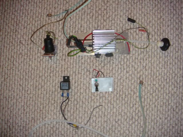
I purchased a used pump and misc. parts from another member here, and what I received amounts to essentially an Aquamist 1s system. I still need a tank, a checkvalve, and a nozzle. Take a look:
Now then, I need to calculate the correct size nozzle before the final order. I plan on injecting water at a rate of about 10% of the maximum fuel flow at peak torque. Peak torque occurs at 6000 RPM on my engine at 12psi, but it's within a few points of that from about 5000-7000 RPM. I have seen several different methods can be used to calculate fuel flow at a given hp, but the results sometimes differ slightly. I used the below:
BFSC(.64) x HP(320fw) = ~205 lbs/hr or ~2150 cc/min fuel flow
Can anyone please verify this calculation?
Next, there's two possible ways to trigger the system: Via boost pressure or RPM signal switch. I'm not precisely sure how to get an RPM signal on/off output from my ECU, but I could learn. Otherwise, I have a boost switch set at 10psi, which is convenient cause I have it but it may cause the system to activate at much lower RPMs.
For those of you more experienced in this arena than I, what would you do?
There is a third option... pre-turbo. I like this option because of the increased turbo efficiency and added AIT cooling in addition to the other benefits. However, these are somewhat uncharted waters, so I'm hesitant to go this route, but it's still on the table...
For a little background, below is a list of my modifications so that others can make comparisons for their own AI system. The engine was rebuilt with reliability in mind and is tuned as such using a standalone engine controller: 280whp @ 12psi. Hopefully AI can help this engine running strong and carefree for years to come, with system upgrades allowing for a more "proper" tune
Mods
Engine
Hurley 3mm ceramic apex race seals
Hurley corner race seals
JDM '99 spec turbos
Tri-Point 3" downpipe
Tri-Point high flow catalytic converter
HKS exhaust
Mazda Competition radiator
ACT Performance street disc
ACT Xtreme pressure plate
XACT ProLite flywheel
Miata thermostat
Tri-Point 8mm ignition wires
Modified airbox
Electronics
AEM EMS
AEM wideband UEGO controller
I purchased a used pump and misc. parts from another member here, and what I received amounts to essentially an Aquamist 1s system. I still need a tank, a checkvalve, and a nozzle. Take a look:
Now then, I need to calculate the correct size nozzle before the final order. I plan on injecting water at a rate of about 10% of the maximum fuel flow at peak torque. Peak torque occurs at 6000 RPM on my engine at 12psi, but it's within a few points of that from about 5000-7000 RPM. I have seen several different methods can be used to calculate fuel flow at a given hp, but the results sometimes differ slightly. I used the below:
BFSC(.64) x HP(320fw) = ~205 lbs/hr or ~2150 cc/min fuel flow
Can anyone please verify this calculation?
Next, there's two possible ways to trigger the system: Via boost pressure or RPM signal switch. I'm not precisely sure how to get an RPM signal on/off output from my ECU, but I could learn. Otherwise, I have a boost switch set at 10psi, which is convenient cause I have it but it may cause the system to activate at much lower RPMs.
For those of you more experienced in this arena than I, what would you do?
There is a third option... pre-turbo. I like this option because of the increased turbo efficiency and added AIT cooling in addition to the other benefits. However, these are somewhat uncharted waters, so I'm hesitant to go this route, but it's still on the table...
Let me see if I understand correctly... this system has a fixed flow. It's either on or off and the flow doesn't change based on pump voltage or other triggers?
If that is correct then the boost switch activated at 10 psi could come on at very low RPMs (sequential 99 twins?) Depending on how much water you inject this may or may not be a terrible thing, it will just be a bit water rich in the lower rpms.
I say hook it up with the boost switch and a nozzle that will flow 200cc. That should be enough considering your lower power configuration and also allow you the benefit of "steam cleaning" more often. If you run into issues you could then figure out your rpm switch, but I don't think 200cc would be enough water even at lower rpms to cause any hiccups.
As far as preturbo, that is what i run @ about 380 cc (for now) on a big single. You're setup is a bit trickier considering you have 2 turbos. I don't think spraying at only 1 turbo is wise, and spraying at 2 would either take 2 nozzles or some creativity. You should also make sure your nozzle pressure is high enough to atomize the water enough to prevent any turbo damage.


Joined: Oct 2001
Posts: 6,279
Likes: 728
From: Florence, Alabama
skip the pre turbo... while it works fine it is way too complicated for your concept... keeping it simple. (which is a good concept)
you can run alot of water through the FD BUT if you raise the water input you have to lean it out alot. of course if you do and you run out of water you then have your engine in jeopardy.
the 10% number sounds good and you are correct that you want max delivery around the peak torque area.
good luck,
howard
I say hook it up with the boost switch and a nozzle that will flow 200cc. That should be enough considering your lower power configuration and also allow you the benefit of "steam cleaning" more often. If you run into issues you could then figure out your rpm switch, but I don't think 200cc would be enough water even at lower rpms to cause any hiccups.
Howard, you also posted in another thread "water will change your charge air temps to the point your air temp correction table will be a factor." Would you please expand on this more?
You weren't kidding! I placed my order for a small tank to mount in the rear storage bin area. Thanks for the tip!
Trending Topics
Thanks, Richard! And thanks for your support over on your forums. You truly do offer unparalleled customer support.
Yesterday, it's alive! I tested the pump as it had been sitting in Fritz's garage for a few... The mag drive pump primed itself and started pumping water through a .7mm jet. It was like the fountains at Bellagio in the palm of my hand It seems this jet would work well too for my application, it will put out around 260cc/min at 8 bar with the alternator running. Minus 1 bar for the checkvalve and another for the pressure differential in the charge pipe, leaving 6 bar of pressure to atomize the water.
Also, I picked up a cable to connect my laptop to my AEM ecu so I can record and analyze engine parameters more closely. I'm going to go out and log some data to determine if the boost comes on at such a low RPM that 260cc of water would be too much. Depending on what this data looks like, I may just use the pressure switch or try and route a spare lead from the ecu to trigger the pump. Which brings me to my next question...
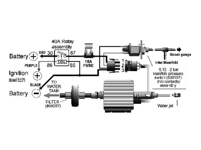
Richard or someone with more electrical experience, maybe you can shed some light on wiring this thing up. I intended to use the boost pressure switch as the activation point, and probably still will, but I'm starting to like the idea of using a lead from my AEM ecu switching the pump based on load and rpm. Below is the schematics for wiring up a standard 1s system as taken from your site:
http://www.aquamist.co.uk
Now, I'd like to break the on/off circuit for the pump (thus activating the pump) based on Xpsi and Yrpm, with the flow itself remaining constant. Below is a configuration for an available 1.5A switched ground...
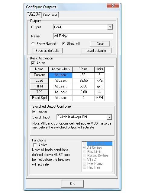
While most of you do not run the AEM system specifically, does it appear that I'm setting up this switch correctly? Should I use a different available output? AEM has been unresponsive so far.
Yesterday, it's alive! I tested the pump as it had been sitting in Fritz's garage for a few... The mag drive pump primed itself and started pumping water through a .7mm jet. It was like the fountains at Bellagio in the palm of my hand
It seems this jet would work well too for my application, it will put out around 260cc/min at 8 bar with the alternator running. Minus 1 bar for the checkvalve and another for the pressure differential in the charge pipe, leaving 6 bar of pressure to atomize the water.Also, I picked up a cable to connect my laptop to my AEM ecu so I can record and analyze engine parameters more closely. I'm going to go out and log some data to determine if the boost comes on at such a low RPM that 260cc of water would be too much. Depending on what this data looks like, I may just use the pressure switch or try and route a spare lead from the ecu to trigger the pump. Which brings me to my next question...
Richard or someone with more electrical experience, maybe you can shed some light on wiring this thing up. I intended to use the boost pressure switch as the activation point, and probably still will, but I'm starting to like the idea of using a lead from my AEM ecu switching the pump based on load and rpm. Below is the schematics for wiring up a standard 1s system as taken from your site:
http://www.aquamist.co.uk
Now, I'd like to break the on/off circuit for the pump (thus activating the pump) based on Xpsi and Yrpm, with the flow itself remaining constant. Below is a configuration for an available 1.5A switched ground...
While most of you do not run the AEM system specifically, does it appear that I'm setting up this switch correctly? Should I use a different available output? AEM has been unresponsive so far.

Senior Member
Joined: Sep 2006
Posts: 402
Likes: 0
From: uk
You need ot get a 5-pin relay.
Pin 85/86 to your ECU drive output. Pin 30 and 87a across the wires as the pressure switch. Now you can remove the pressure switch. ( your pressure switch is a "normally closed" type, goes open-circuit on boost)
Wire the rest of system according to the above diagram.
Pin 85/86 to your ECU drive output. Pin 30 and 87a across the wires as the pressure switch. Now you can remove the pressure switch. ( your pressure switch is a "normally closed" type, goes open-circuit on boost)
Wire the rest of system according to the above diagram.
Also, what do you mean by, "Pin 30 and 87a across the wires as the pressure switch." Would you please expand on that?
I was thinking maybe I could use a spare +12V switched output in lieu of the ignition switch. Could I use that 12V switched output into 86 for on/off, ground 85, power 30, 87 to pump harness and leave the pressure switch circuit open? Or is the switched ground method as described above still best?
Thank you in advance for taking the time to help me understand this!
Senior Member
Joined: Sep 2006
Posts: 402
Likes: 0
From: uk
Ok, I've got your AQ 40A relay in front of me, I'm having trouble grasping this wiring. What do you mean, do I wire one switch ground output from the ECU to both 85 and 86 or two separate outputs?
Also, what do you mean by, "Pin 30 and 87a across the wires as the pressure switch." Would you please expand on that?
I was thinking maybe I could use a spare +12V switched output in lieu of the ignition switch. Could I use that 12V switched output into 86 for on/off, ground 85, power 30, 87 to pump harness and leave the pressure switch circuit open? Or is the switched ground method as described above still best?
Thank you in advance for taking the time to help me understand this!
The following diagram should work well. You need to purchase a separate relay fo rthe ECU. The system relay should be wired as indicated.

Richard, brilliant! Thank you, this makes everything clear. Removing the pressure switch from the equation makes this concept even simpler!
Edit: Out of curiosity, could you do a diagram for a 5-pin relay? I am such a noob when it comes to wiring!
Edit: Out of curiosity, could you do a diagram for a 5-pin relay? I am such a noob when it comes to wiring!


I do all my wi systems pre turbo.
I have down a twin turbo car Pre turbo. It isnt complicated at all.
Use two solenoids, and two jets all controlled via one relay triggered by ecu.
Also its good thats your gona have wi at 12psi. But really. With WI, you want some more boost. Another 5-10psi on top of what you have now. Your going through of alot of effort to reduce knock levels at 12psi which would be close to 0 with a good tune.
Atomization is the biggest thing to me when using wi. The better it atomizes, the better it works.
I would offload what you have, get your self a 250psi pump and 250cc jet from coolingmist and one of their shut off solenoids.
Much better then you what you have and cheap. You wont need anything else if your ecu can trigger a relay.
Here are some pics of my setup. Very simple and easy to make work.(obviously with twins their is two solenoids and 2 jets).
And as you will see in my pics. My jet is directly pointed at comp wheel, and at a very short distant. 0 damage to comp wheel over around 9-10 months now.
The jet size in the front of my turbo for most of the time was 1150cc jet. HUGE.....
If you want more info let us know.
^This setup is awesome! You hoons in Aus really have a handle on this pre-turbo stuff. To be honest, the more I read about pre-turbo, the more I'm compelled to implement this powerful resource. Thank you for posting the above info. I would also direct anyone interested in more info to this large pre-turbo thread on the Aquamist forums, it's one of the best sources I've found.
However, several factors are keeping me from making this leap:
I want this system to be simple insurance against bad gas, hot weather, traffic, and/or any other pre-ignition or detonation causing issue.
Even with pre-turbo injection, I don't think my '99 spec twins can handle much more than 15psi with prolonged reliability in mind. So, 15psi is my target boost, no plans on going single in the near future because I like the wide powerband the twins provide. Plus, I don't have the fuel system or ignition for more than ~350fwhp.
I bought this used ERL/Aquamist magnetic drive pump, pressure switch, relay, nozzle, and hose for $65 (Thanks, Fritz!). Total cost will be <$100 it just doesn't get better than that! Massive boost and stone-cold temps is ultimately what I want... But simple, cheap insurance is what I need right now.
its at 30psi now. Will be putting another 10psi or so if it will let me soon.
I got told by alot of people it would not even rev. How wrong they were lol.
I do have an air filter for it yes.(its another attachment that i havnt put on yet).
I got told by alot of people it would not even rev. How wrong they were lol.
I do have an air filter for it yes.(its another attachment that i havnt put on yet).
Senior Member
Joined: Sep 2006
Posts: 402
Likes: 0
From: uk
I have updated the drawing to include the relay pinout.

Senior Member
Joined: Sep 2006
Posts: 402
Likes: 0
From: uk
... I was thinking maybe I could use a spare +12V switched output in lieu of the ignition switch. Could I use that 12V switched output into 86 for on/off, ground 85, power 30, 87 to pump harness and leave the pressure switch circuit open? Or is the switched ground method as described above still best?
Thank you in advance for taking the time to help me understand this!
The centre pin is the only recommended way to enable/disable(grounded) the pump correctly.
I cannot recommend using the main system relay to active the system, the internal circuitry require a few milliseconds to stabilise. Prolong usage of the main system main damage the internal circuitry of the pump.
The centre pin is the only recommended way to enable/disable(grounded) the pump correctly.
The centre pin is the only recommended way to enable/disable(grounded) the pump correctly.
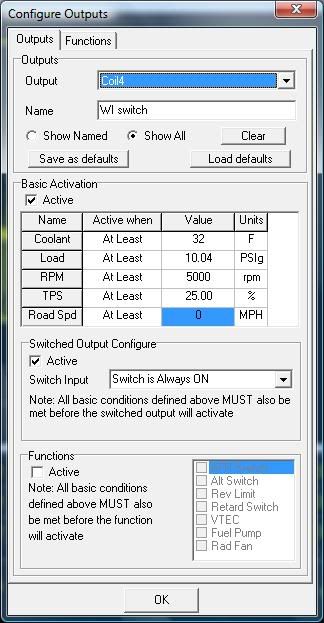
I'm posting as a resource to anyone else desiring to configure a similar switch on their own ecu. This is all very exciting to me

Thread
Thread Starter
Forum
Replies
Last Post
24seven_dada
3rd Generation Specific (1993-2002)
20
Nov 10, 2018 12:03 PM
Jeff20B
1st Generation Specific (1979-1985)
73
Sep 16, 2018 07:16 PM