When you click on links to various merchants on this site and make a purchase, this can result in this site earning a commission. Affiliate programs and affiliations include, but are not limited to, the eBay Partner Network.
Damage to an eyelet (barrel) is never a good thing. Typically, the eyelet is attached to the copper run underneath the solder mask (either the white or green mask). When the barrel is pulled from the board then the copper run is severed. It sounds like too much heat was applied to the solder joint and/or the leg of the capacitor was still connected to the eyelet when it was being removed. Take some photos, especially up-close and personal photos of the eyelet and socket. There may be a chance that it could be saved. Otherwise, you may have to epoxy the barrel in place then run a jumper from the capacitor leg to the trace that was broken. If this exceeds your scope of expertise then I would recommend finding a local electronics tech who specializes in micro-miniature component & board repair.
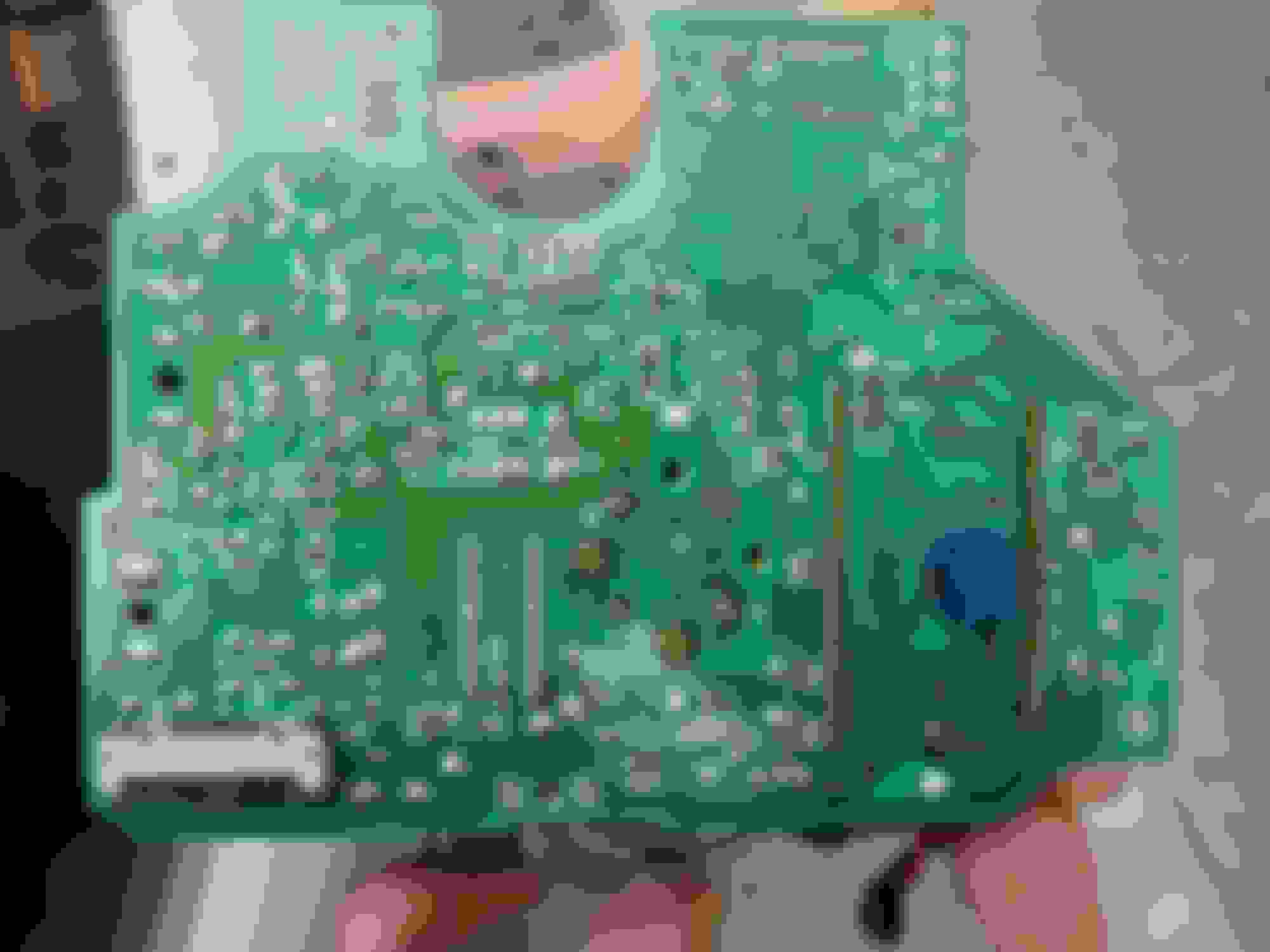
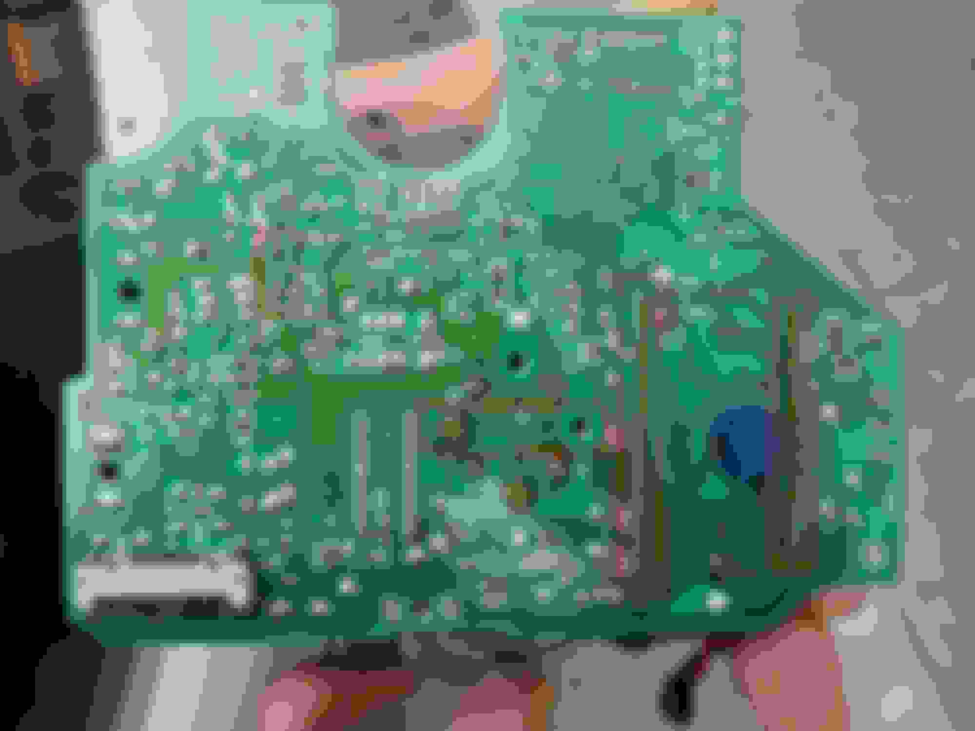
Here are pictures of the top and the bottom of the board. Unfortunately, the eyelet definitely came out with the old capacitor, I can see it completely attached to the previous capacitor legs. Let me know if you need any other photos and what you think I could do to fix it. Thanks!
Last edited by RapidCancel; Mar 22, 2019 at 12:15 AM.
Thanks for showing the photos of the cap and your board. You will need to remove the barrels from the capacitor. I will do my best to explain how to repair the board. I will caution you that there is a small chance of failure here.
Step 1: Remove the barrels from the capacitor legs. This could be achieved by using a solder iron at the top of the barrel and "pushing" it down the leg. Use flux to help the solder flow through the barrel.
Caution: Do not damage the barrels or make them get out-of-round.
Step 2: Test fit each barrel onto your board. Do they easily slip in and out without much effort?
Step 3: Clean the area with isopropyl alcohol then allow to dry.
Step 4: Apply a small amount of epoxy along the side walls of each hole on the board.
Note: Use a toothpick to apply. The goal is to have the epoxy create a mechanical bond to each barrel's side walls and the side walls of the board.
Step 5: Insert each barrel into the hole and ensure they are fully seated in the holes.
Note: The lip on each barrel is typically the top. Therefore, push the barrel in from the top of the board towards the bottom until it seats flush or just beyond the solder mask.
Step 6: Remove excess epoxy from the top and bottom of each barrel.
Note: The speedo board has 2 layers of traces, one on the top and the other on the bottom. It is VERY important to ensure no epoxy is on the top and bottom areas of each barrel. Excess build up of epoxy will prevent solder from making an electrical connection between the barrel and trace.
Step 7: Allow the epoxy to set and cure. I recommend leaving it sit for 24hrs. This step requires patience! So please, don't rush the curing time.
Step 8: (As required) If any residual epoxy is found on the top and bottom of the barrel then carefully scrape/sand/dremmel off the excess.
Caution: Do not damage the solder mask when sanding, filing, or scraping off excess epoxy. This will expose the copper trace below. If traces become exposed then it could be patched with clear acrylic nail polish.
Step 9: Insert replacement capacitor then apply flux to the top and bottom portions of the barrel.
Caution: Observe polarity of the capacitor, match neg (-) leg to neg (-) hole and pos (+) leg to pos (+) hole. Otherwise, the odometer will not work and cause you frustration!
Step 10: Kink 1 leg of the capacitor slightly so it would stay in place for vertical alignment.
Step 11: Apply solder to the bottom side of each joint.
Step 12: Verify that solder flowed through the hole (barrel) to the top. The solder should look like a small mountain peak.
Step 13: Trim leads on the bottom of the board down to the solder joint.
Step 14: Verify that an electrical bond is created with a multimeter along each solder trace. Follow the trace in the photo below when testing the positive leg. It is important to test "through" the leg. Place the multimeter at points above and below the Positive leg of C3. If you see continuity or measure a short then you are good! If you measure an open then that is bad. Repeat this step for the bottom side of the board.
Here are some photos that show your board versus a board that has the top solder mask partially removed. The red circle on each photo indicates the location of C3. The orange arrow indicates the Positive (+) side.
Red Circle shows location of capacitor C3. Orange arrow is the Positive side.
Red Circle (slightly harder to see) shows the location of capacitor C3. Orange arrow is the Positive side.
Note the orientation of the copper traces that is beneath the white solder mask. The barrel must make an electrical connection to both the top and bottom sides. Otherwise, the electricity stops at the broken edge of the trace.
I need to do this soon. My odometer intermittently works. It worked when I pulled it all apart and then just plugged in the bare gauge board. Then when i reassembled the whole gauge hood and put it all back together it doesn't work lol. It's going to be tricky to trouble shoot.
Did you ensure the ribbon cable from the speedo board was plugged into the instrument cluster?
If your odometer intermittently works then I would advise that you inspect the board for any capacitor damage. When acid from a leaked capacitor sits on a board for too long it does more damage to the board and other components around it. Remember, the gauge sits in a vertical position so the acid will run down the length of the board. Please read the earlier posts in this thread which address this concern.
Hi George, yes, I made sure the ribbon cable was plugged in properly. That was actually what I suspected was the initial cause. I think I may use some alcohol to clean the contacts though as I'm not confident they are seating and making proper contact. There is discoloration on the back of the board where the contacts for the ribbon cable are soldered but that's the only thing that appeared unusual. Because of this, I reassembled the cluster (without the hood) to test if it still didn't work. To my surprise, the odometer lit up perfectly. Thinking I was at end of job, I reassembled the entire thing and now it doesn't work again (speedo and all gauges work fine). I'll have to get a second look at the caps and see if there's anything I missed.
If the odometer comes and goes then it sounds like a cap or two may need to be replaced on the speedo. Please share a couple of photos of that discoloration on the back of the board. You could also post photos of any suspect capacitors.
Edit:. Sorry for breaking the rules. Apparently it's forbidden to let everyone know they have options for repairing their 25 year old parts even when those repairs require a level of sophistication and tools to do the job properly that aren't at the disposal of most home hobbyists but anyhow enjoy the pics I guess. Some tips from an expert tho:
Don't listen to anyone that says soldering temps are going to destroy your components on board
Dont listen to anyone that says you shouldn't replace capacitors with higher voltage rated replacements even if the capacitance is the same.
GLHF!
Last edited by zensation; Mar 31, 2019 at 03:19 PM.
This is an update to Post 115 which has a correction to the Speedometer Connector (CON1). Specifically, Pin 13 is now labeled as "Water Lvl Low Lamp". Use this photo of CON1 to reflect the proper list of pins and their location.
In case you are looking for a quick fix for a bouncing tachometer needle then you could check out this thread as an alternative or supplemental to the information posted here. Otherwise, feel free to discuss/post pics of problems with the tach and/or speedometer circuit boards here.
This thread shows recent members' success with re-flowing solder to all of IC1's solder joints. It is referenced here: The Dreaded Tachometer Issue
Thank you for the complements about the speedo threads! I'm glad it helps you identify and repair any suspect components. Your post was moved to this thread because it can be better discussed here. The other thread is a discussion on the parts list and part numbers for the Speedo board components. It helps others order replacement parts or research part numbers for the unidentified components.
To answer one of your questions: No one has tested the Zener diodes, to my knowledge.
Upon review of your circuit board pic, it revealed a several things. First, the solder joints on the positive side of ZD5 and ZD7 are new. There is too much solder on ZD5 that makes it look like a bridge across ZD7. Luckily, that positive side of ZD5 and ZD7 are connected to the circuit board's ground plane. So there is no harm there. Otherwise, the excessive solder would make a future removal of those components more difficult. Moreover, these look like the original zener diodes. Only the solder was refreshed. Therefore, the part number stencilled on the body appear to match the documented ones. Second, capacitor C3 was replaced. I suspect the solder joints along ZD5 and ZD7 were touched up during the replacement of C3. Third, the solder mask that surrounds the positive sides of ZD5 and ZD7 reveal the copper trace. This may have been caused by leaked acid from C3 and/or C2 (just above the super large ZR6). The black stains on the exposed copper is evidence of the acid eating it away. Fourth, something appears to be "wet" above/around the stencil marking on the board for ZD5. Could that be some sort of topical seal? Lastly, I noticed fresh solder on one solder joint to TR7. That component too may have been touched up when C3 was replaced.
If I would bet dimes to donuts, I would bet C3 vomited its acid and then it ran down the length of the circuit board for a very long time. Thus causing collateral damage to solder masks, joints, and other components.
Does your Speedo board currently work? Is your odometer working? If everything appears to work, I would recommend using a non-acetone based nail polish remover along the exposed area of the solder mask. You may want to wet the area under/around ZD3 to remove any residual acid (it will continue to feed unless neutralized). The nail polish remover should clean up the acid and may help clean up the black stains on the exposed copper trace. Afterwards, wipe down the same area with isopropyl alcohol. This will neutralize any residual acid and nail polish remover on the board. Finally, I would use a clear coat of nail polish over the exposed areas of the solder mask. This will seal the exposed copper trace from open air and reduce any further oxidation.
Some other points of interest: take a closer look at the cathode (negative) side of ZD3. The solder joint looks cracked/broken. This may have a negative impact on the board's operation if it is broken. Additionally, inspect the leads of C2 and IC2 for potential damage caused by acid leakage from capacitors. I also suggest to verify the legs of each component are still physically connected to the solder joints. This may seem like a no-brainer however, I had one experience where the acid from C3 ate through the leg of another component. That leg was still connected to the solder joint but it was broken where it met the body of the component. The acid just ate the leg off from the body!
I recently helped @rotarypower101 repair his speedometer board in this thread: Alarm Buzzer above 2000 RPM, possible Malfunctioning Over Revolution Warning Alarm? It was not related to a blank odometer but that thread dove into detail about the repair of several capacitors on the speedometer board. His symptoms were an alarm buzzer sounding above 2,000 RPM. Basically, the speedometer board thought the RPMs exceeded 7,000 RPM, which is when the over-rev alarm would normally sound. After he was done making the repairs, the speedo board came back to life. *Knocking on wood*, his initial testing provided positive results!
That thread features great dialog and excellent photos to catalog his journey to repair a broken speedo board. IMO, that thread is a great companion to this troubleshooting thread. It offers explanations that may not have been discussed in this or other threads. So take a moment to review it for some additional insight.
It may help someone.
Looking for problems on a speedometer i took this reference voltage from a working speedo.
The voltage has been taken with all the cluster connected and key in ON position. Also the tachometer were connected which is not in picture. Picture is only for illustration purpose. 1 V 12,41+
2 V 12,36+
3 V 12,38-
4 V 0,00 5 V 4,59+
6 V 12,37-
7 V 12,37-
8 V 0,15- (V11,74 if I trigger the buzzer disconnecting the coolant sensor)
9 V 11,90-
10 V 12,37- 11 V 11,58+
12 V 8,87+
13 V 10,56-
14 V 12,48- 15 V 12,14+
+ voltage are taken grounding the black tester lead and checking each pin of the speedo with the red tester lead
- voltage are taken connecting the red tester lead to the positive battery and the black tester lead on each pin.
Thank you for sharing those photos! I am also happy to see the alcohol cleaned up the leaked acid.
I would recommend replacing the 11 capacitors highlighted from Post 42. Capacitor C15 does not need to be replaced because it is a different type and lasts much longer.
The capacitors to replace are: C1, C2, C3, C4, C6, C9, C11, C12, C13, C16 (mini cap), and C17 (mini cap).
Please take a few more close-up photos of the areas around IC1, C1, ZD3/TR7, and C3? I want to check the solder joints and legs to all the components affected by the leaked acid. Examples of close-up photos can be referenced in Post #38 and Post 26 (in the same thread). I am worried that IC1 may have serious damage from the leaked acid so please, take several photos around that IC chip. I suspect the conformal coating may only be damaged. Clean IC1 again with isopropyl alcohol and a tooth brush to ensure alcohol is scrubbed in between IC1's legs.
One more note: Take a close-up of ZD3. What is the stamp marked on its body?
Last edited by Gen2n3; May 2, 2020 at 11:53 AM.
Reason: Note about ZD3.
Thank you for sharing those photos! I am also happy to see the alcohol cleaned up the leaked acid.
I would recommend replacing the 11 capacitors highlighted from Post 42. Capacitor C15 does not need to be replaced because it is a different type and lasts much longer.
The capacitors to replace are: C1, C2, C3, C4, C6, C9, C11, C12, C13, C16 (mini cap), and C17 (mini cap).
Please take a few more close-up photos of the areas around IC1, C1, ZD3/TR7, and C3? I want to check the solder joints and legs to all the components affected by the leaked acid. Examples of close-up photos can be referenced in Post #38 and Post 26 (in the same thread). I am worried that IC1 may have serious damage from the leaked acid so please, take several photos around that IC chip. I suspect the conformal coating may only be damaged. Clean IC1 again with isopropyl alcohol and a tooth brush to ensure alcohol is scrubbed in between IC1's legs.
One more note: Take a close-up of ZD3. What is the stamp marked on its body?
I really hope that this picture are what You expected.
i cleaned all with cotton toothbrush and some part hard whit a copper wire.
IC1 looks good to my eyes.
About ZD3 i replaced once so is not original anymore.
Thanks for the support
The photos help but please zoom in on the legs of some transistors and diodes. See the photos below.
Please do not use a wire brush (copper or otherwise) on the printed circuit board. A copper wire brush will remove the solder mask. That is the painted top and bottom layers. You do not want to reveal the copper traces underneath the mask. An old tooth brush or an acid brush with isopropyl alcohol will clean a circuit board.
Would you please clean the areas I highlighted in red circles of this photo? There are some spots that look fuzzy and other spots may have old acid on it.
Clean these areas again with isopropyl alcohol and a soft tooth brush.
I would also recommend re-soldering ZD3. From the photos, the solder looks broken and sunken. The solder should form a small mountain peak. If the mountain peak looks like Mt. Etna then there is too much solder! LOL
Please take more photos of these transistors and diode arrays highlighted in the photo. Use the zoom function to get close. I want to make sure these legs are not damaged by leaked acid from the capacitors.
Perfecto! Thank you for the zoomed-in photos. They show all legs on the transistors and diode arrays (IC2, TR5, TR6, TR7, DA1, DA2) are not broken. Sometimes, the acid will eat away a leg where it meets the shell of the transistor. The other locations look clean too!
I have 2 more recommendations from this new set of pictures. First, use the tooth brush and isopropyl alcohol to clean the legs and bodies of the components (IC2, TR5, TR6, TR7, DA1, DA2). Your new close-up photos show small amounts of acid residue between the legs and bodies of these components. This is a safety step to ensure all acid is neutralized and removed. You do not need to post more photos when done. Just make sure each component is very clean. You should not see any dark spots. Second, clean the legs and area of C16 and C17. The negative (cathode) side of C17 looks like it has acid on the solder joint.
If you have problems cleaning some spots on the board with a tooth brush then you can use an acid brush (see photo). The longer hairs of the acid brush can get into the hard to reach areas that a tooth brush cannot get.
Example of acid brush.
I look forward to hearing about your repair to the speedometer circuit board.
Thank You very much George,
I will keep You updated .
I had to make a lot of force in order to remove the black build of acid on the board, i will try whit your brush
No problem. You do not need to use a lot of force to clean the components. It does not have to pass a "white glove inspection." Make sure the alcohol gets in between the spaces those spaces. When you feel it is clean then it should be ok.
I Used a lot of alcohol (specific for electronics component) but was really encrusted. So I switch from cotton fioc to paper towel but I had to push a bit hard whit a tweezers.
I'm ordering all component I hope to get it by the end of the week
1. Replace the solder on ZD3. I mentioned this before but looking at the backside confirms that it should be replaced. One leg does not look good.
2. The screws to mount the speedometer face should oppose each other. Specifically, they should be mounted in pattern shown by the red box.
3. You can clean the dried flux on the LCD pins with isopropyl alcohol and a tooth brush. It will make the solder joints look shiny, just like the others.


 any suggestion is really appreciated.