When you click on links to various merchants on this site and make a purchase, this can result in this site earning a commission. Affiliate programs and affiliations include, but are not limited to, the eBay Partner Network.
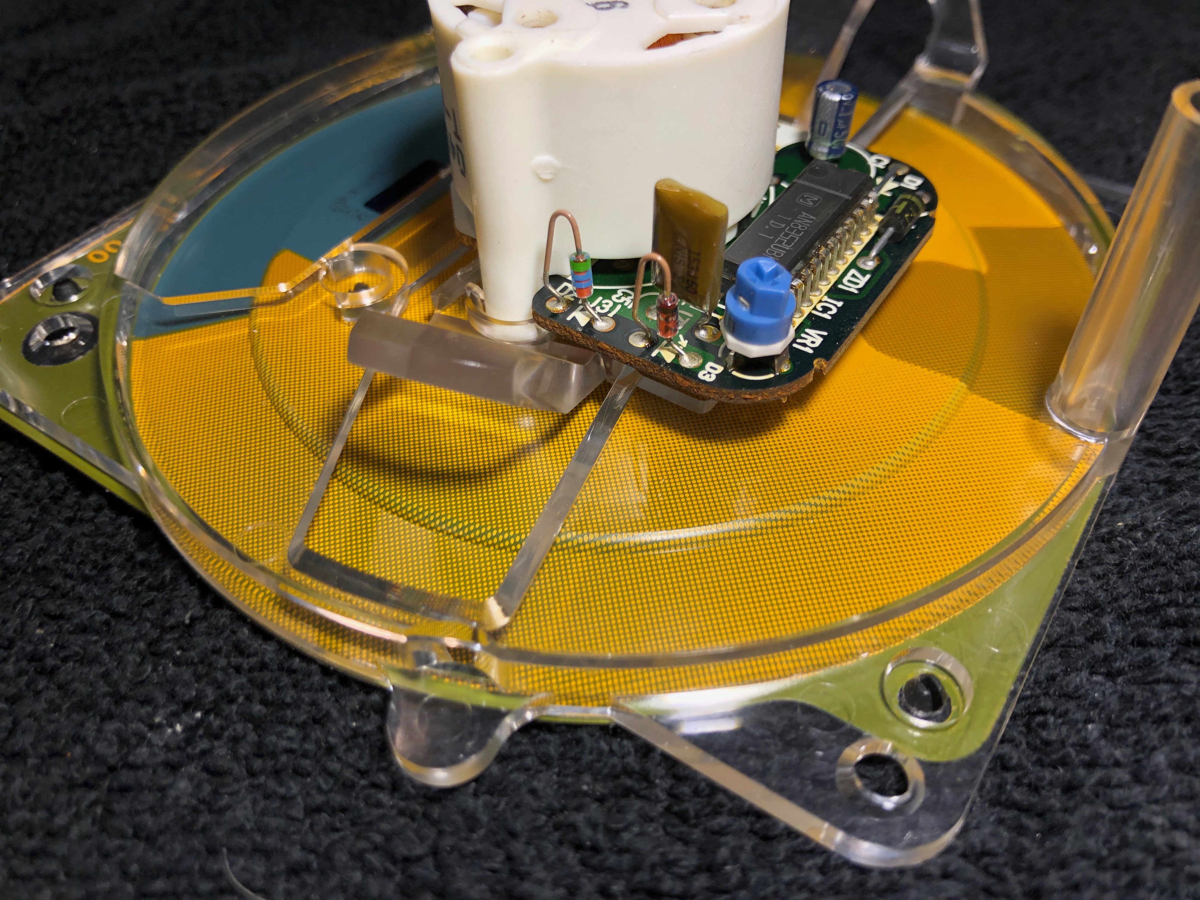
Thanks for digging into the instrument cluster and taking some preliminary photos of the speedo.
Please desolder the speedo face because we need to take a deep dive into this board! There are several problems that we need to address.
I'll try to briefly explain with these edited photos:
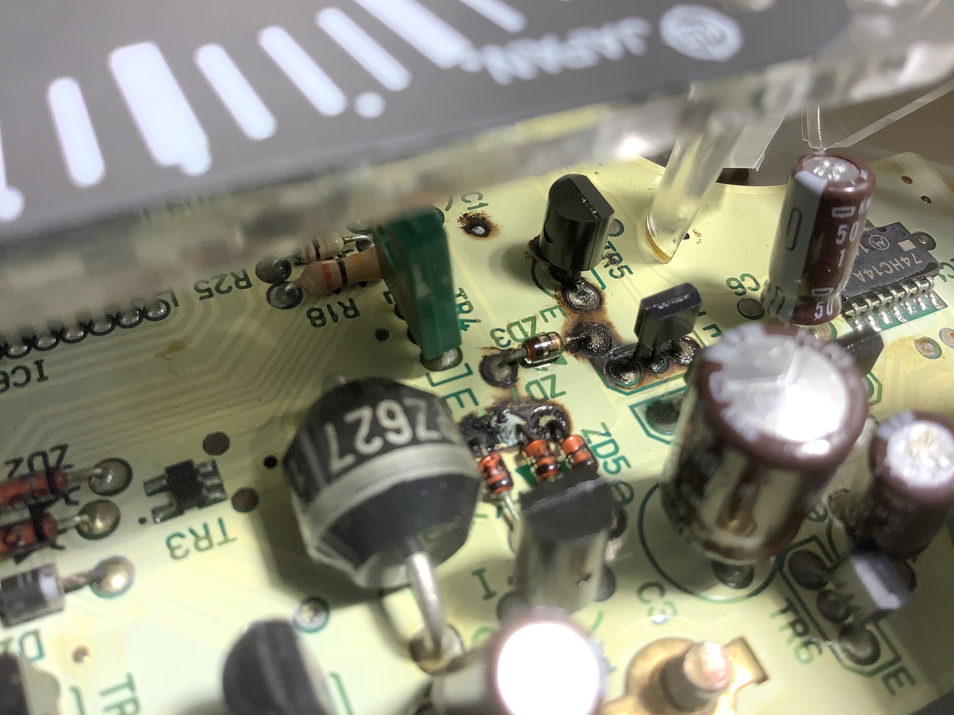
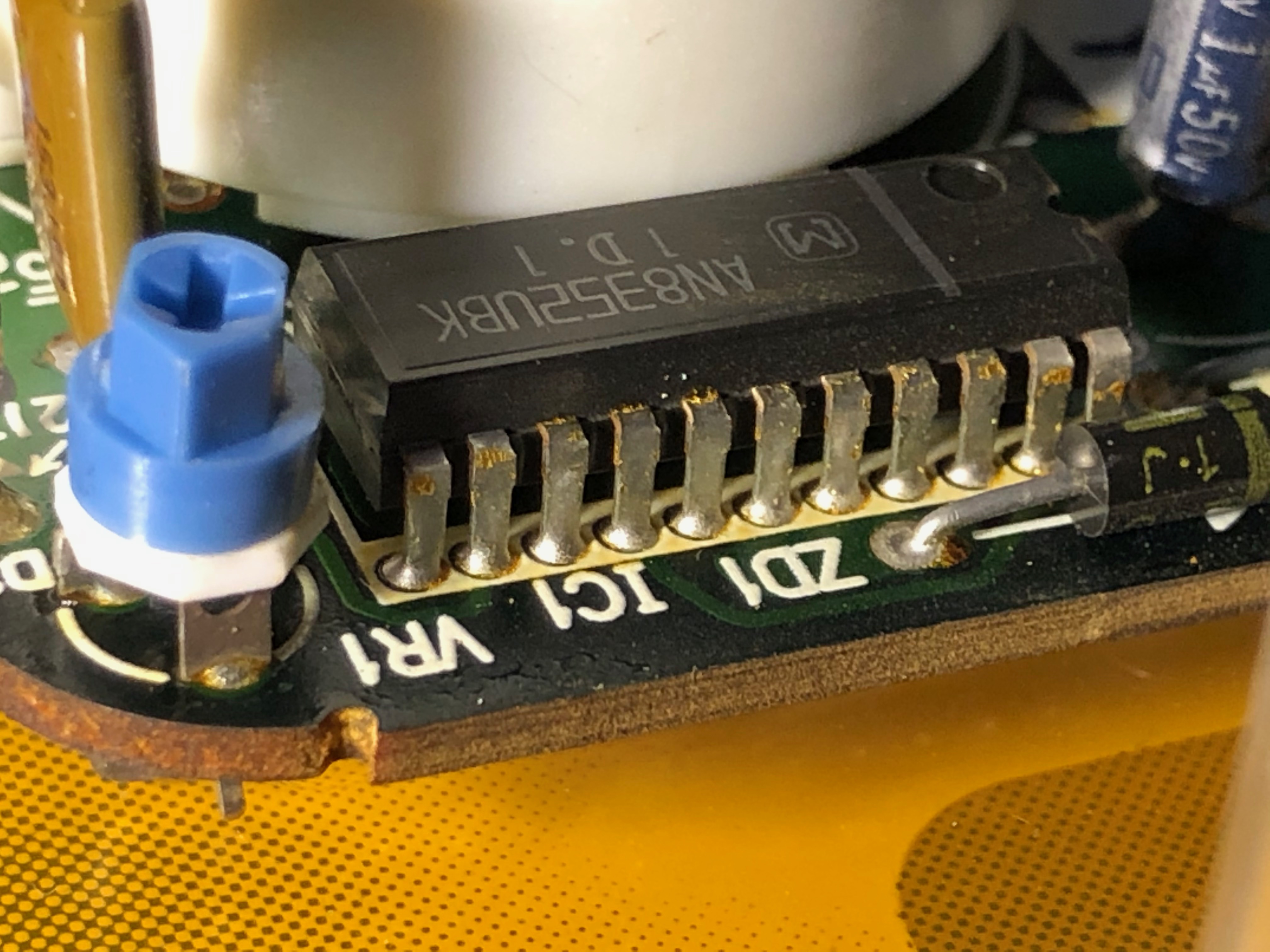
These red boxes are very BAD! Bad as in they look fried. I suspect the board may be physically charred in certain spots.
In the above photo, the components in these red boxes are either damaged from leaked electrolyte or suffered a large voltage spike and are dead. The cause could be many things - a current spike from somewhere else or a current spike that resulted from leaked electrolyte across these eyelets. The latter would be a short circuit condition. This may be the reason why your initial measurements passed but subsequent measurements fail. The circuit board looks like it took a catastrophic failure in between the measurements. It is doubtful that this damage was caused by taking measurements (if you had that question in mind).
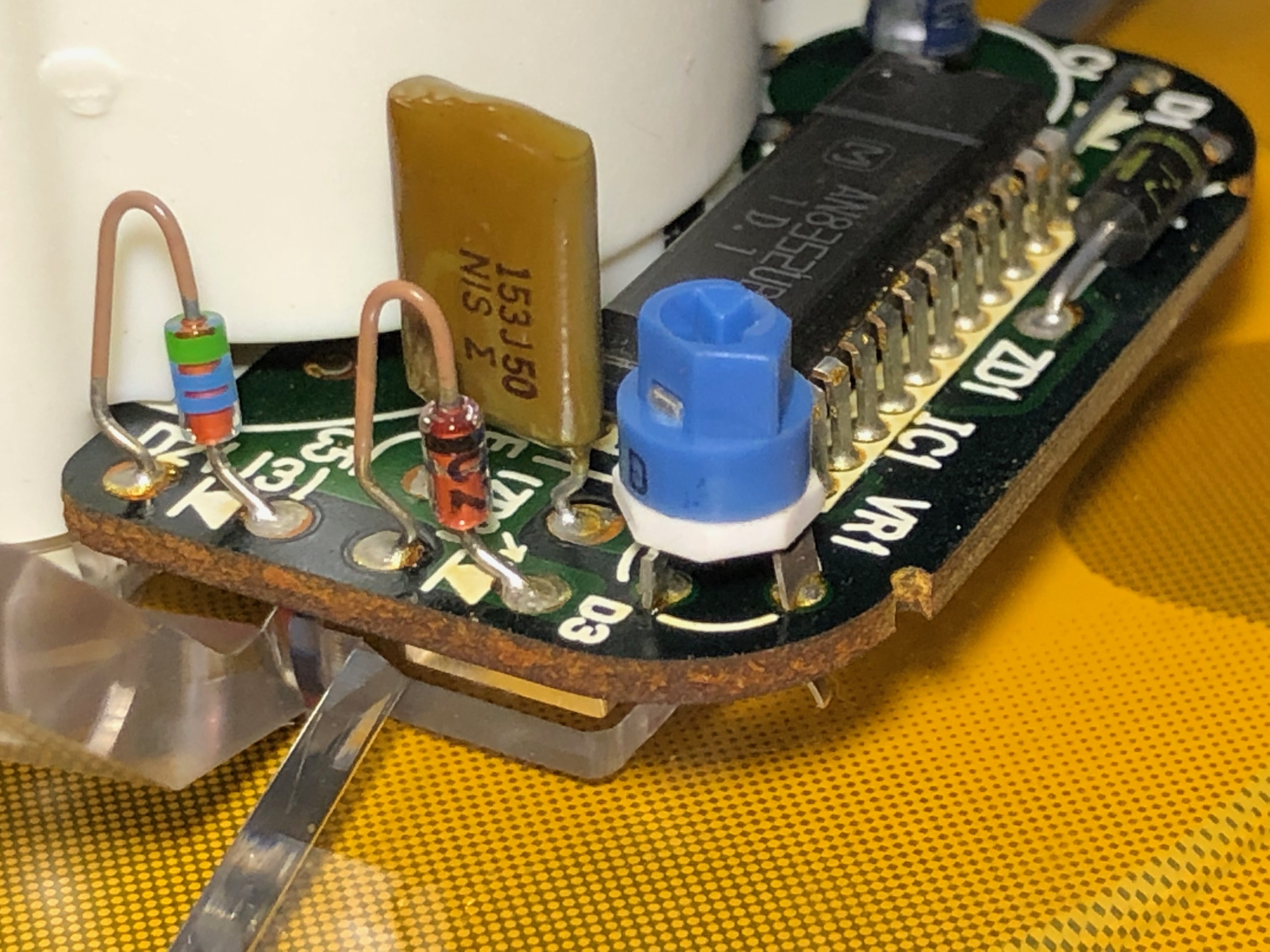
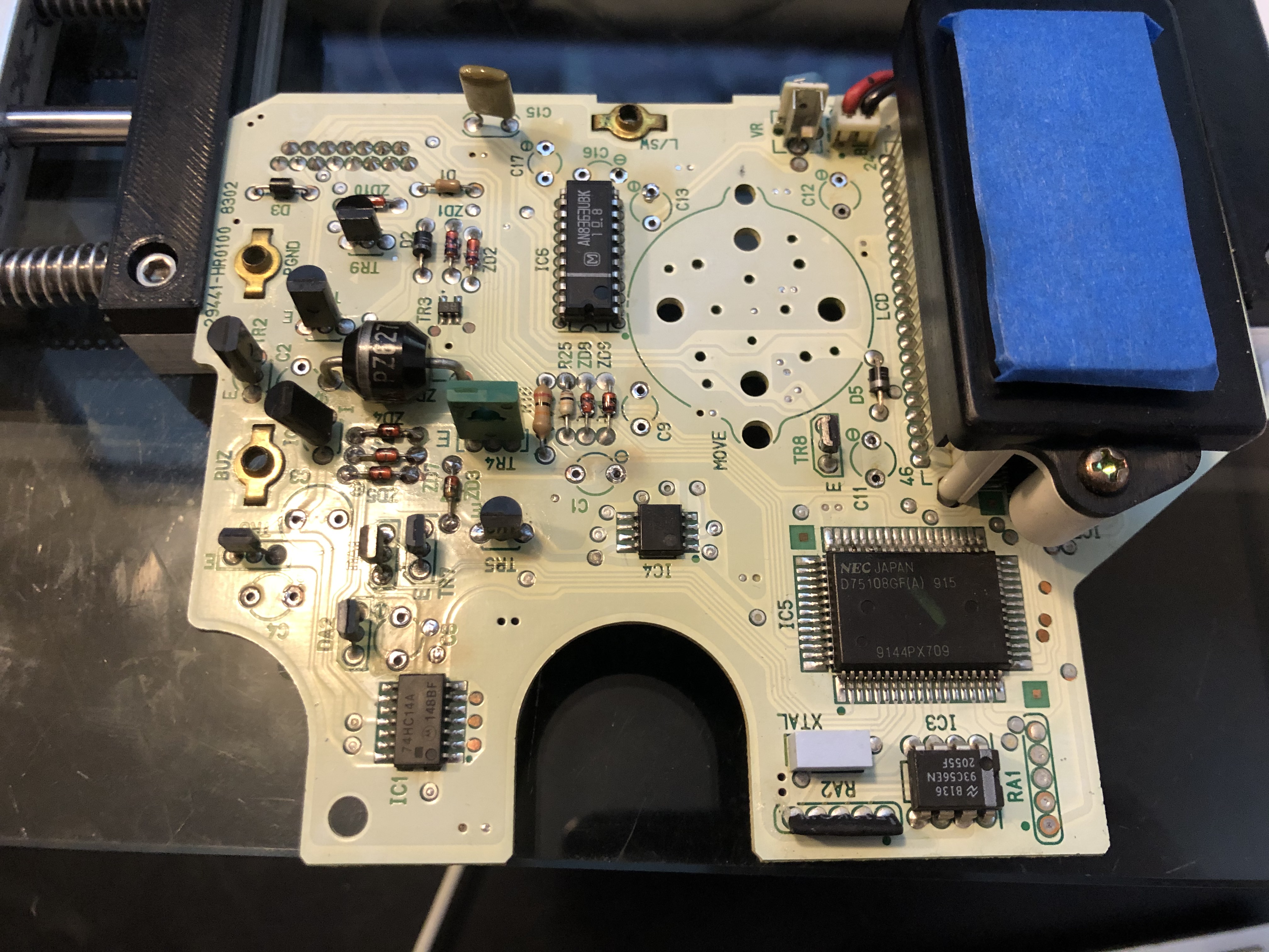
I ask that you desolder the speedo face and before doing anything else, take photos of these specific areas from various angles. Get in close and use the highest quality setting on your camera. Do not resize them. These photos will serve as the "before" set. Next, take several q-tips and isopropyl alcohol to clean around these components. Do your best to remove as much mung as possible without damaging the components. From this angle, be VERY careful around the legs of TR5. One of these legs appears to be broken or partially severed. Additionally, the red box to the left of TR5 has an exposed section of the PCB. That is normal but what isn't normal is the scorch marks that surround it.
After these areas are cleaned to the best of your ability, take a second set of photos. Let's call this the "cleaned" set. Once done, please post the "before" and "cleaned" sets. We must determine whether or not the board could be saved. Burned components are easier to replace but a damaged PCB is a headache! Based on these initial photos, the board may need professional help! To prepare you for a possible solution, you may just need to replace the speedo board because of its extensive damage. However, let's not throw the baby out with the bath water just yet. We still need to verify the extent of the damage. Afterwards, we can make the call - fix it or replace it. These boards are getting harder to find and they are expensive.
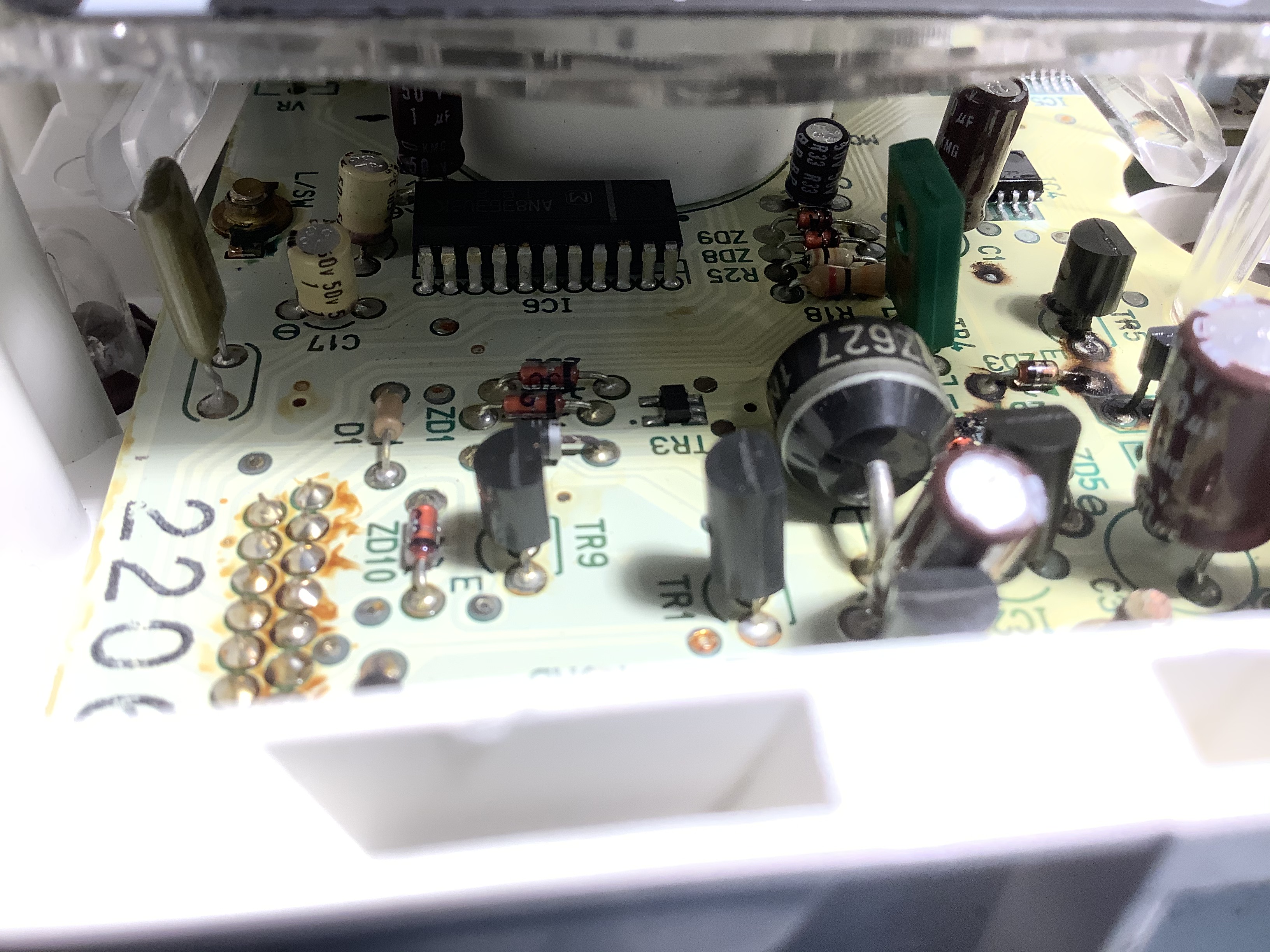
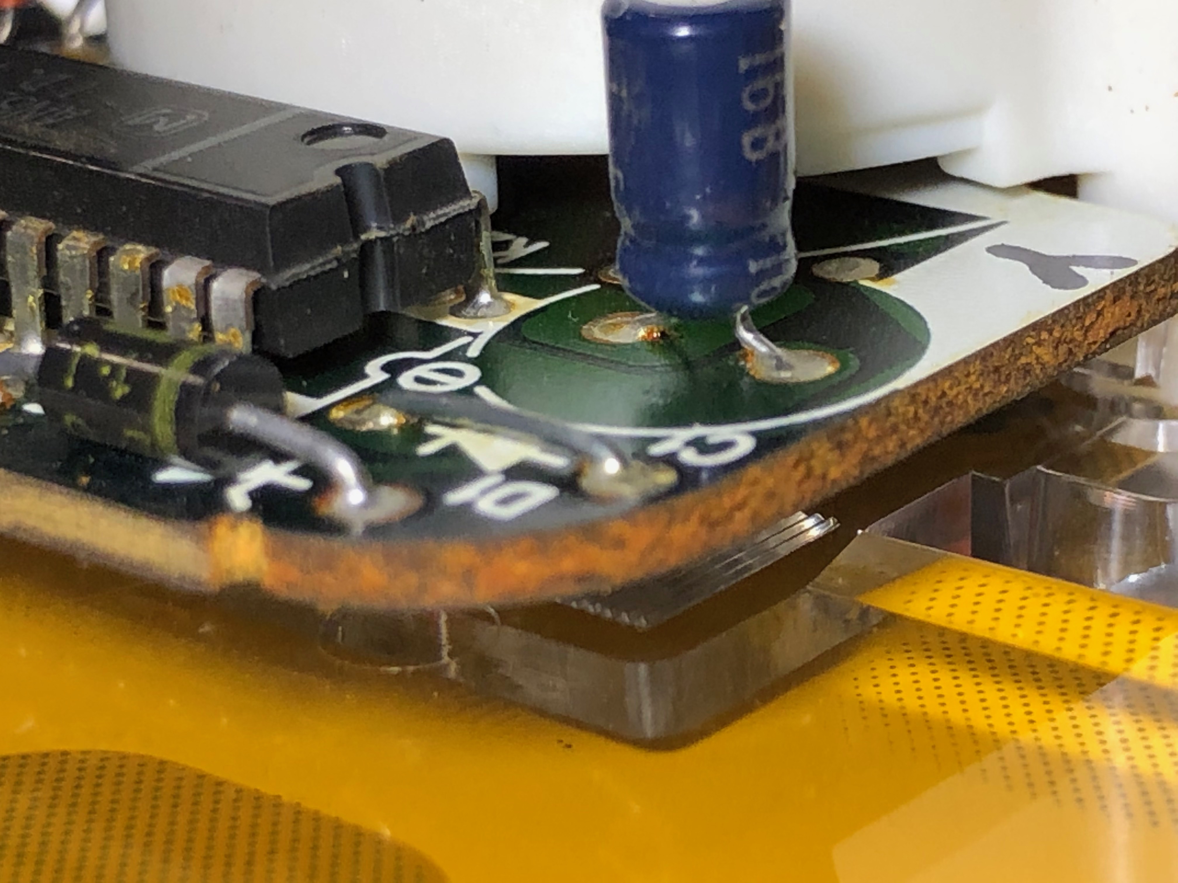
The capacitor, C16 inside the red box (left) does not look good. Note the brown ring at its base and the swelled top.
In the 2nd photo, C16 looks like it failed. The brown ring at its base and swelled top are signs of a bad cap. I would recommend replacing it along with C17 (directly in front of it) if we go in the direction of repairing the speedo board. Use the same approach of taking photos with these locations as well. Take a look at R25 - it appears to have one eyelet that is blackened/charred. Use the same cleaning method described above. You should get better photos of this area once the speedo face is removed.
These 3 capacitors are the ones that fail the most. They are C3, C4, and C6. They appear to have swelled tops.
In the 3rd photo, capacitors C3, C4, and C6 are the most susceptible to failure. Typically C3 spews out electrolyte and it runs down the board. Because the board sits in a vertical position, this acid just runs down the length of the board and eats everything in its path. This leaked electrolyte could be the cause of the short circuit and all of that charring.
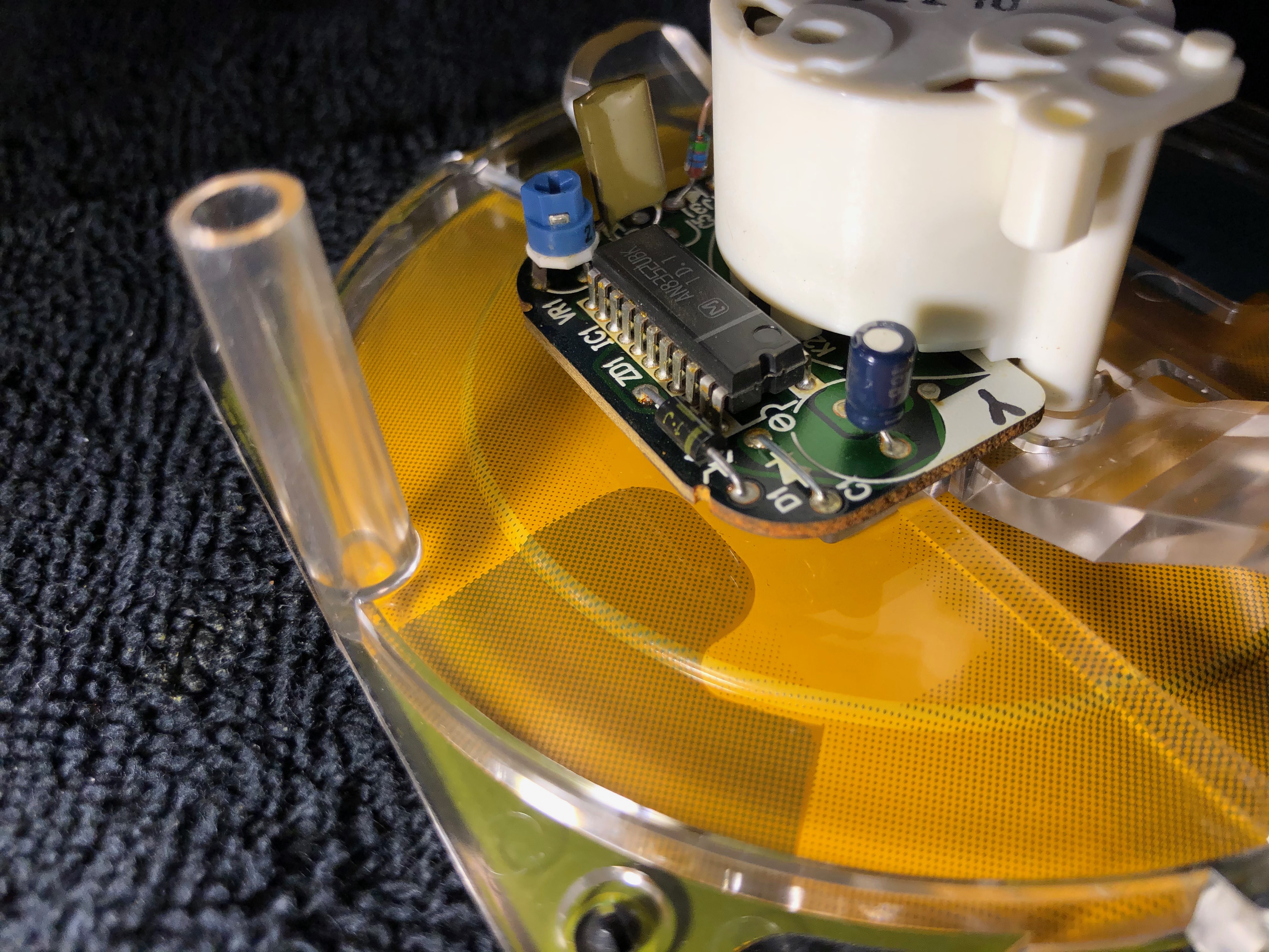
What does your tachometer look like? Take a photo of its circuit board. But please, only show the top side (component side) of the board. Do not remove the tach face & needle.
Regarding the PFC, I am not an expert in its use, theory of operation, or installation. Our forum has a dedicated section for it, look in the Engine Management section for the PFC. Other gurus like @DaleClark would be more qualified to answer how to properly ground your PFC. I also know the PFC forum has a FAQ. It should cover proper grounding of the PFC.
Oh, in case you ask, we will save the "after" photos when the board is repaired (or maybe replaced).
P.S. If you cannot locate a USDM speedo then consider getting a JDM speedo. DaleClark has a JDM to USDM speedo conversion thread that has helped many other members. If you do need a new speedo then give a call to Ray Crowe first. He should be able to source one for you.
It would be unfortunate to repair everything, only to have what ever caused this to repeat this failure!
Based on the look of it, what ever happened fried these components with heat, I think�
Is that a common thing on a low voltage DC PCB to short from small traces of capacitor electrolyte? I don�t see a lot of evidence of damage from corrosion.
C3 is noticeably bulging, and is in a very good position to leak over the most damaged area.
Have you seen anything remotely similar to this before from a leaky cap? A short rather than corrosion?
I am certainly NO expert on the topic, but I don�t see much corrosion or high levels of effected areas from electrolyte if I were to describe it currently. Admittedly from very limited angles.
Several of the diodes seem to have a dark �black scorched� residue away from the epicenter of all the skid marks. D2, D3, seem to have obvious surface scorch material on the leads, even D4 completely on the other side of the board behind the digital odometer has a similar darkened char reside on the leads.
Simply as an observation that feels noteworthy.
I can say fairly confidently, given the proper advice I can fix nearly anything on a PCB! Seen and fixed much worse and spend a good deal of time working on components like this �
The technical expertise and background is my known Weak area�I know enough to be dangerous, with guidance I feel very confident I can build and fix nearly anything in front of me.
Saying that, I can accept when an object is too far gone, and will defer to advice and experience on that topic.
C16 C17 I noticed the same thing, I assume this is electrolyte creeping up the shrink? I noticed this on that extra board I have also.
1 more thing: please continue with the plan to clean those char spots.
If you take a look at my troubleshooting thread, there are examples of burn & char marks. There should be other photos that document electrolyte leakage. It will look similar to charing because there is an exothermic reaction between the acid, solder mask, wire leads & traces.
Copy all. Tach looks good but will double check on my computer. Using the GT app to read & reply.
Take some pics of the backside of the board, with attention to these key areas. Then post. What are the other marks you mentioned on the backside?
What is the GT app? Searched and didn't get anything on "GT app forum" I assume it is some forum portal specific to mobile apps?
Working on the Speedo board now, just removed the actuator.
The other marks are just general comments about noticeable areas that seem different from others, and seem to be obvious and noticeable details seemingly worthy of mentioning as POI.
The good news: That was electrolyte that you cleaned from the board and the other components do not appear to be damaged. The even better news: the PCB is not damaged! Even more better news: the board can be repaired!
Thanks for those up close photos. I would prefer to have the photos posted in the thread. So that I may directly comment on them and so other members could evaluate them in the future. Links to 3rd party photo hosting sites are great for the short term but do not last past a few years. When photos are posted on the RX7Club, they are not going anywhere and members could see them without having to use a separate site or have to stop reading the current thread (bouncing back and forth).
Based upon the photos you posted, I would recommend a full capacitor replacement. Just the solid state components. Use my thread for parts here: Speedometer Parts Thread. Post 76 in that thread has the updated list of components with part numbers.
The reason for the full capacitor replacement: Install fresh capacitors that replace the one that failed (especially C3) and the others that will fail shortly after. This is "cheap" insurance that the board will not fail for the remainder of its life.
Could you post some close up photos of just C3? It is a perfect example of capacitor swelling from the top and bottom. Those photos will help others identify a bad cap.
I had no idea it could look like a proper scorched PCB, I was completely convinced that was a thermal meltdown, and it is right in front of my eyes, the little lifted bubbled surfaces following plausible trace paths between what appears to be associated components, the remote test point all by itself over there blackened and bubbled…
Some Notes while cleaning:
ZD3 looks discolored compared to my spare board or to the other zeners near it.
ZD4 ZD5 ZD7 had a deep thick coating that required what seemed like excessive mechanical abrasion to remove.
Concerned about the top pad on ZD4, if I were to guess, the plating on top of the PCB is gone, and all that remains it the through hole material.
Does electrolyte attack/target copper specifically more virulently than other typical metallic materials used in electronics?
Two components really look like they took a beating - DA1 and TR7. That is because they were the 1st components in the wake of flowing electrolyte. Aren't you glad that you cleaned up the board with alcohol? I have seen that before, where leaked acid appears to look like charring and scorch marks.
I saw the eyelets on the Zener diode pack, ZD4, ZD5, and ZD7. They look fine. The anode (positive side) of ZD5 and ZD7 are tied to the ground plane (on the back side of the board). If you are worried about the solder joint on ZD4 then measure resistance between the positive leg of ZD4 on the top side and the bottom pad of R6 (SMD component) on the bottom side of the PCB. This will test the wire trace between the top side of the board to the bottom side of the boar without damaging the eyelet. If it measures a short (should be 0.2 ohms) then the wire trace is good. If it measures an open then the trace is broken. BTW, the anode (positive leg) of ZD4 is the side that is opposite of the black line on the diode. The black line on a diode always points to the negative material, sometimes called the cathode.
If you are worried about an exposed eyelet around ZD4 then you could dab it with a clear coat of nail polish. That will act as a topical touch-up sealant. The one thing you must remember about doing that: you must remove the clear coat with nail polish remover before you do any solder work to ZD4. Otherwise, I wouldn't worry too much about it.
I see the discoloration you mentioned on ZD3. It should be fine. Testing a Zener diode is tricky. It normally involves desoldering it then inserting the Zener into a test circuit. I don't recommend doing that. Just leave it in place. You can use a crude test and compare it to my measurement as follows:
1. Use the diode function on your DMM.
2. Place the red lead on the anode (positive side) of ZD3 and the black lead on the cathode (negative side) of ZD3.
3. The DMM should measure about 813 ohms. This is known as a "forward bias" of the diode.
4. Swap the lead so that the red lead is on the cathode (negative side) of ZD3 and the black lead is on the anode (positive side) of ZD3.
5. The DMM should measure infinity, or "1 " or "O/L". This is known as a "reverse bias" of the diode.
Note: You may hear one beep when the diode is forward biased. That is normal, dependent upon the multimeter. Additionally, a Zener diode operates in a different way from a normal diode. Basically, it's a one-way valve with unique operating zones.
I'd also like you to apply a second (or third, etc) coat of isopropyl alcohol to those affected areas again. This time, use an acid brush or a soft-wide bristle model paint brush. Pay attention to the legs and underside of those components. This will further neutralize any remaining electrolyte. Pay particular attention to DA1 and TR7 but don't apply a lot of pressure. You want to use a dabbing motion to allow the bristles to do the work. Then let it air dry.
To answer your question, the electrolyte will eat thru just about everything in its path when left alone. I cannot quantify how fast it eats through copper or other metals because I don't know the pH level of the acid. However, I saw the result of this acid eat away the leg of one transistor because it was allowed to sit for an undisclosed amount of time (let's say 1yr+). It ate the leg at a very unusual spot - the bottom edge of the transistor. I speculated the acid pooled at that "low" point because of gravity and the "wicking" property of the metal leg. It was barely visible and I spotted it well after I made several repair attempts on that board.
Thanks for the photos of C3. It doesn't look that bad, minus the slight bulge in the top lid.
Here are some photos from your cleaned photo album that have some of my observations:
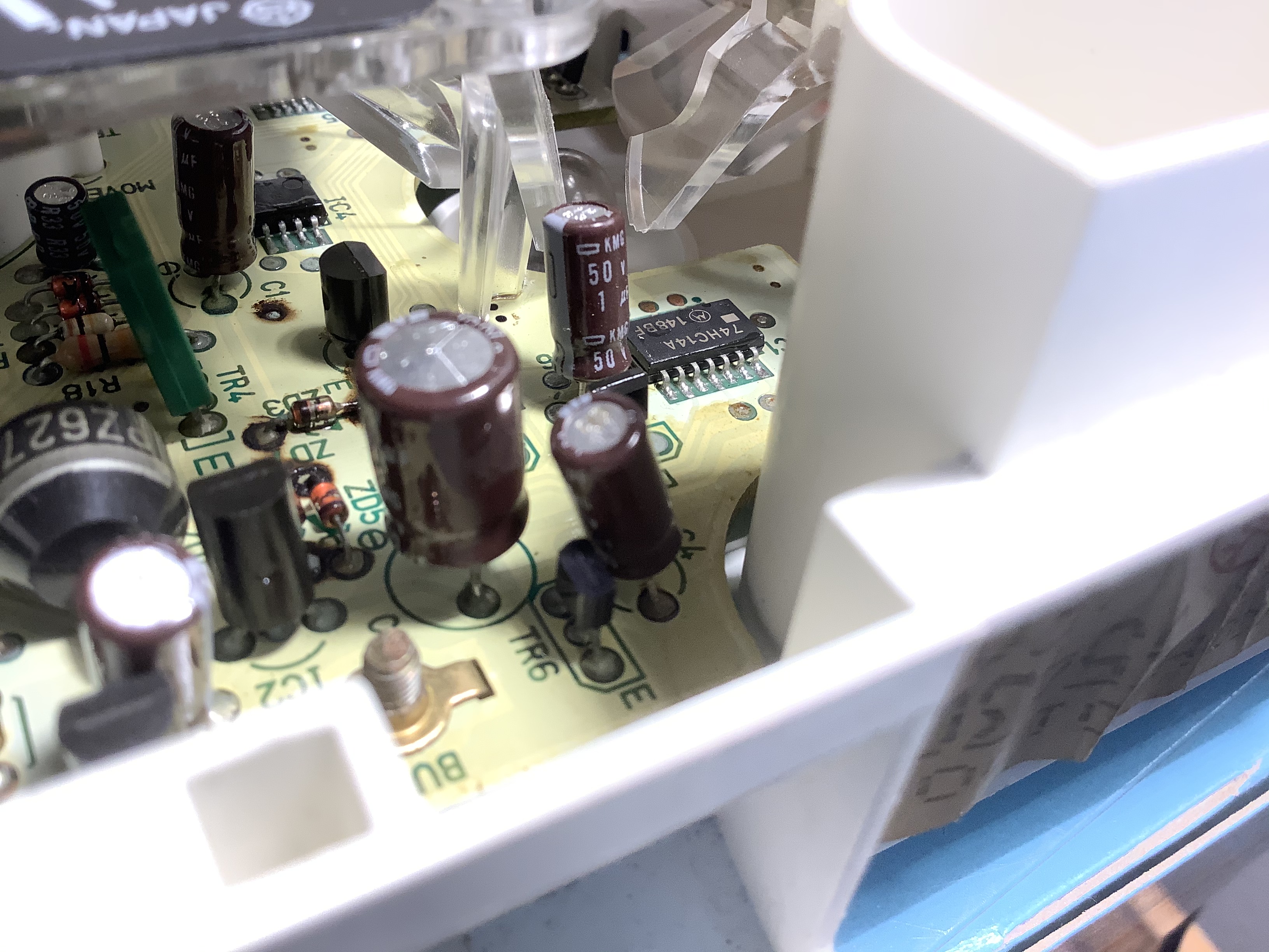
What capacitor is on the left? Is that C6? That one looks like it "gave up the ghost". Notice the swelling/deformation along the base. Note the removal of plating on the legs of DA1.
Again, the capacitor on the left looks like C6. DA1 and TR7 is front and center. Use an acid brush with isopropyl alcohol along the legs and bottom edge of these components. I see a green tinge on the bottom of TR7 and DA1.
This looks like a good example of a failed capacitor. It should be C6. Note the abnormal blister along its bottom edge.
Again, this should be C6 that appears to have a blister around the narrow ring. You can also see the acid ate away the plating on 3 legs (might be DA1).
A different shot of C6. IC1 is in the foreground. Note the warping of the bottom section of C6.
Two components really look like they took a beating - DA1 and TR7. That is because they were the 1st components in the wake of flowing electrolyte. Aren't you glad that you cleaned up the board with alcohol? I have seen that before, where leaked acid appears to look like charring and scorch marks.
YES, when I first saw that I was certain it was a overloaded circuit.
Perhaps from a failed component that would be beyond my ability to track down. I doubt there is high current in that area, but I have seen that, and it was remarkably similar in likeness.
I saw the eyelets on the Zener diode pack, ZD4, ZD5, and ZD7. They look fine. The anode (positive side) of ZD5 and ZD7 are tied to the ground plane (on the back side of the board). If you are worried about the solder joint on ZD4 then measure resistance between the positive leg of ZD4 on the top side and the bottom pad of R6 (SMD component) on the bottom side of the PCB. This will test the wire trace between the top side of the board to the bottom side of the boar without damaging the eyelet. If it measures a short (should be 0.2 ohms) then the wire trace is good. If it measures an open then the trace is broken. BTW, the anode (positive leg) of ZD4 is the side that is opposite of the black line on the diode. The black line on a diode always points to the negative material, sometimes called the cathode.
Measures 0.2 ohm, so all good it appears.
If you are worried about an exposed eyelet around ZD4 then you could dab it with a clear coat of nail polish. That will act as a topical touch-up sealant. The one thing you must remember about doing that: you must remove the clear coat with nail polish remover before you do any solder work to ZD4. Otherwise, I wouldn't worry too much about it.
Only a concern if there was a trace leading to it that was unseen. I doubt this is a multilayer board with near 80s era consumer level tech... but it was worth noting.
I see the discoloration you mentioned on ZD3. It should be fine. Testing a Zener diode is tricky. It normally involves desoldering it then inserting the Zener into a test circuit. I don't recommend doing that. Just leave it in place. You can use a crude test and compare it to my measurement as follows:
1. Use the diode function on your DMM.
2. Place the red lead on the anode (positive side) of ZD3 and the black lead on the cathode (negative side) of ZD3.
3. The DMM should measure about 813 ohms. This is known as a "forward bias" of the diode.
4. Swap the lead so that the red lead is on the cathode (negative side) of ZD3 and the black lead is on the anode (positive side) of ZD3.
5. The DMM should measure infinity, or "1 " or "O/L". This is known as a "reverse bias" of the diode.
Using a Fluke 17B+:
If I measure "ohms of resistance" on ZD3 I get 13.42 kilo ohms my malfunctioning board and 13.32 kilo ohms on my spare board in both directions.
On ZD3 when I use my "diode mode" black lead to negative cathode and red lead to positive anode I get 0.714v
red lead to negative cathode and black lead to positive anode I get 1.185v
And a very similar result with my extra board.
Am I perhaps misunderstanding anything here? With the voltage /ohm as well as the resistance discrepancy that is seemingly closely repeated on both boards?
Note: You may hear one beep when the diode is forward biased. That is normal, dependent upon the multimeter. Additionally, a Zener diode operates in a different way from a normal diode. Basically, it's a one-way valve with unique operating zones.
I'd also like you to apply a second (or third, etc) coat of isopropyl alcohol to those affected areas again. This time, use an acid brush or a soft-wide bristle model paint brush. Pay attention to the legs and underside of those components. This will further neutralize any remaining electrolyte. Pay particular attention to DA1 and TR7 but don't apply a lot of pressure. You want to use a dabbing motion to allow the bristles to do the work. Then let it air dry.
Will do!
To answer your question, the electrolyte will eat thru just about everything in its path when left alone. I cannot quantify how fast it eats through copper or other metals because I don't know the pH level of the acid. However, I saw the result of this acid eat away the leg of one transistor because it was allowed to sit for an undisclosed amount of time (let's say 1yr+). It ate the leg at a very unusual spot - the bottom edge of the transistor. I speculated the acid pooled at that "low" point because of gravity and the "wicking" property of the metal leg. It was barely visible and I spotted it well after I made several repair attempts on that board.
Thanks for the photos of C3. It doesn't look that bad, minus the slight bulge in the top lid.
Thank you for taking time to help a random stranger!
Here are some photos from your cleaned photo album that have some of my observations:
What capacitor is on the left? Is that C6? That one looks like it "gave up the ghost". Notice the swelling/deformation along the base. Note the removal of plating on the legs of DA1.
C4 I believe, to the middle left is DA1 to the rear middle left TR7 to the right DA2, and on the far right C6 I believe
Again, the capacitor on the left looks like C6. DA1 and TR7 is front and center. Use an acid brush with isopropyl alcohol along the legs and bottom edge of these components. I see a green tinge on the bottom of TR7 and DA1.
I will take another stab at it, I actually cleaned that one again after being able to see it in the photos. (I have one of those little USB/WiFI microscopes, I find it useless... you don't happen to use one you can recommend? )
This looks like a good example of a failed capacitor. It should be C6. Note the abnormal blister along its bottom edge.
She's ripe!
Again, this should be C6 that appears to have a blister around the narrow ring. You can also see the acid ate away the plating on 3 legs (might be DA1).
I have both my malfunctioning board and extra board I can stack and see the side by side difference, to my untrained eye the "don't look that bad by themselves" but having a direct comparison makes it apparent for the ones that are not so pronounced.
A different shot of C6. IC1 is in the foreground. Note the warping of the bottom section of C6.
She has a little foopa going on there...
I assume the game plan is to simply replace all caps, and hope for the best? Are there other places in this car susceptible to this issue to worry abut also? Similar to CPU2? Any other body modules that are critical to look into?
I am asking for advice on capacitor brands and lines to purchase on a ask electronics reddit post, would you have any advice? I don't foresee this type of failure if repaired being the ultimate demise of this car, but I have absolutely no intentions of parting with it, and I have at least ~30 years it took for this to cause a issue with it left...
If there are trustable brands, I would love to try and do the best I can, unless its just all a crap shoot?
Its a shame you can't just throw tantalums at it, I don't suppose they make a through hole package in the required voltage and farad capacities that would be suitable? Or not cause some unforeseen issue as a substitute?
Furthermore I don't suppose they typically design for this phenomena? placing caps at the bottom of a vertical board rather than the top? Perhaps isolating caps and employing an air gap on vertical boards?
Has capacitor technology improved at all for electrolytics where this is less of a problem? Or is 30 years just asking too much of a device of that design?
Last edited by rotarypower101; Feb 18, 2020 at 12:47 AM.
Good to hear that the solder joint to ZD4 is good. Based upon your measurements of ZD3, it sounds like it checks out fine. Dependent upon the multimeter, the diode function would either display voltage or resistance. The important thing to note is when a diode is forward biased the value should be small. When the diode is reversed biased, the value should be considerably larger. I have a cheap-o Harbor Freight DMM that displays resistance for the diode function. A proper DMM, like your Fluke 17B+, would display the bias voltage.
Upon further inspection of those photos, the damaged capacitor is C6. See how close that cap is to IC1? The black component behind that capacitor is DA2. It could only be C6. Ha! Foopa (fupa, actually).
Regarding the capacitor replacement, the list of part numbers on my parts thread will provide many more years of use. They are either made by Panasonic or Nichicon and are excellent replacements. The speedo board requires the use of electrolytic caps because the circuits they connect require a specific polarity.
As you said, the game plan is to replace the capacitors. That should bring your speedo board back to life. There is a chance that you may have to re-examine the board further. We can only do so much from a visual inspection.
Remember, auto manufacturers need to make a profit from every vehicle sale. They design a product based upon many compromises. It has to last for a specific time and they use parts from the lowest bidder. I don't believe the Mazda engineers thought about product longevity, such as capacitor lifecycles. Basically, I wouldn't burn up too many brain cells over it.
Be advised, we may have to do more troubleshooting because all we did was perform a visual inspection. If everything goes well then we will celebrate!
Cannibalizing consumable items from one board to the next is a bad idea. Please do not replace bad caps with more bad caps (or potentially bad caps). I would suggest getting a few spare caps in case you booger something up.
You seem rather confident behind a soldering iron. If you would like a refresher or learn about some tips & tricks then check out my General Soldering Tips & Tricks thread. Or you could offer some advice of your own! I have not worked with SMD components before - not with the proper tools at least. So maybe you could add value to that thread?
Is this a recommended replacement as well? Due to age or preventative maintenance?
Or simply for completeness of the parts list and documentation?
Other than the electrolytic capacitors are there some other components that would be �wise� to order, hedging bets they may be needed as a common or typical failure?
In response to any soldering, I would like to help where I am able.
But I am not a formally trained operator by any measure�
Simply been using one since I was able to run a screw driver and tear anything apart out of curiosity and mod�
So while I feel supremely confident and have very wide breadth of experience in any consumer grade device, I don�t have any authority to assert what is �correct� or �right�. But I would certainly supply any advice upon request based on my experiences specifically.
Soldering is a strange thing, I feel from my perspective people are afraid of it, or screwing something up more than lack the capacity to do it well.
I have a ME background, so maybe its a small bit of understanding small details like insulating oxides, heat transfer, and other small details that gets me past the basic hurdles even in the worst scenarios� but I have been doing it since I was a little kid with poor tools, its almost fun with good tools.
C15 doesn't need to be replaced unless there is evidence that would support its replacement - such as burned up wire traces. I didn't notice anything unusual about it on your board.
You may have read earlier in that parts thread that C15 has a code stamped on it. It took me a while to decode it. I wasn't 100% sure that it was properly decoded because there are many standards to capacitor codes and my research was purely hypothetical. After a while, I used an LCR meter that has the ability to test inductors (L), capacitors (C), and resistors (R), hence LCR. The meter confirmed my hypothesis with a small margin of error. Now, the original format of that capacitor is no longer made, so I chose the closest type of capacitor based upon its datasheet specifications.
I also want to address something that concerns me. I found your reddit post asking others the same question you asked me about the quality of components. It happens to be a copy & paste of those components listed on the Speedo Components list thread.
My concerns are:
A. The exact question you posed to that forum was answered in our forum. It was specifically answered by the originator of that thread.
B. Give credit where credit is due. You could have cited one or 2 components and provide those reddit users with a background.
C. Replacement part numbers, both manufacturer and warehouse specific numbers, were provided to make it easy for others to purchase or do their own research.
D. Do you know how much time and energy was spent researching those components?
E. Why seek outside confirmation? Especially when you can hear it from the horse's mouth (who also did the research).
F. Have you read that parts list thread? It is more than just a "use this part number" thread. It documents the journey such as C15's measurements and invites other members to contribute to the parts list.
By posting to reddit, you are asking a different group of people to do the research for you. Is that really necessary? Are we conducting a double-blind study or something? In all, do you not trust the information and research presented? Would you feel more comfortable with another member helping you repair your speedo board?
That was not the intention at all.
I can edit and cite where that list comes from if that is at all a issue, or completely remove it if requested. I was not thinking that far ahead, just a random quick thought I could ask and maybe learn about the topic of capacitor brands. Of which I know nearly nothing other than to match ratings.
I posted that list from a cut and pasted list I was using as an organizational tool while putting together an order.
My intuition was the response to that type of post would be �Depends on the specific type of components needed in question� so it made sense at the time to include it.
I was not asking for any substitutes, simply hoping I could learn if there were brands more likely to offer reliability as a generality for electrolytic capacitors.
That was the intention anyway�
Maybe I misinterpret that threads wealth of information from inexperience, but I didn�t see anything that helped me understand if there were more reliable brands to consider.
If it helps, I apologize if I presented it poorly, and am more than happy to correct or remove anything you feel is incorrect to post. Just searching for information that is ambiguous at best to me.
Thank you for the explanation. The need to edit posts outside of this forum is not necessary. In the future, please cite where your information originates so others (either here or elsewhere) could better understand your question (and perspective). I don't mind an argument to use Brand X over Brand Y. Please, do some independent research then present an argument for discussion.
My background is in electronics. I am a retired Navy Aviation Electronics Technician with 26 years of experience. I troubleshot and repaired many circuits from various devices, such as radio, radar, navigation, aerial photographic equipment, and weapons systems in Navy aircraft - mostly F-14 Tomcats and F/A-18 Hornets. I am very familiar with burned up circuit boards, solid state components, and their repair/replacement. I share this experience with our members when it comes to electrical/electronic repair. When identifying suitable replacement parts for the speedometer, I and a few other members spent several hours researching datasheets and specifications for several components. We looked at component polarity (for the caps, specifically) temperature ranges, tolerance levels, part availability, and even the physical dimensions for replacements. I measured some components with a caliper just to be certain the replacements would fit and orient themselves on the board.
Therefore, recommending Brand X over Brand Y for component replacements would be a complex answer. One manufacturer would have the right criteria while another would not. Generally speaking, the Nichicon or Panasonic electrolytic capacitors typically met the criteria for use in the speedo board. Does this satisfies your curiosity? I applaud your enthusiasm for knowledge. May we continue with your board repair?
How did you fare when ordering replacement parts for the speedo?
Therefore, recommending Brand X over Brand Y for component replacements would be a complex answer. One manufacturer would have the right criteria while another would not. Generally speaking, the Nichicon or Panasonic electrolytic capacitors typically met the criteria for use in the speedo board. Does this satisfies your curiosity? I applaud your enthusiasm for knowledge. May we continue with your board repair?
That helps bring into focus that the selection has been curated much more carefully than I had perceived, thank you for taking the effort to detail that.
How did you fare when ordering replacement parts for the speedo?
Well, I think..., received my components late yesterday evening, and so its time to move forward!
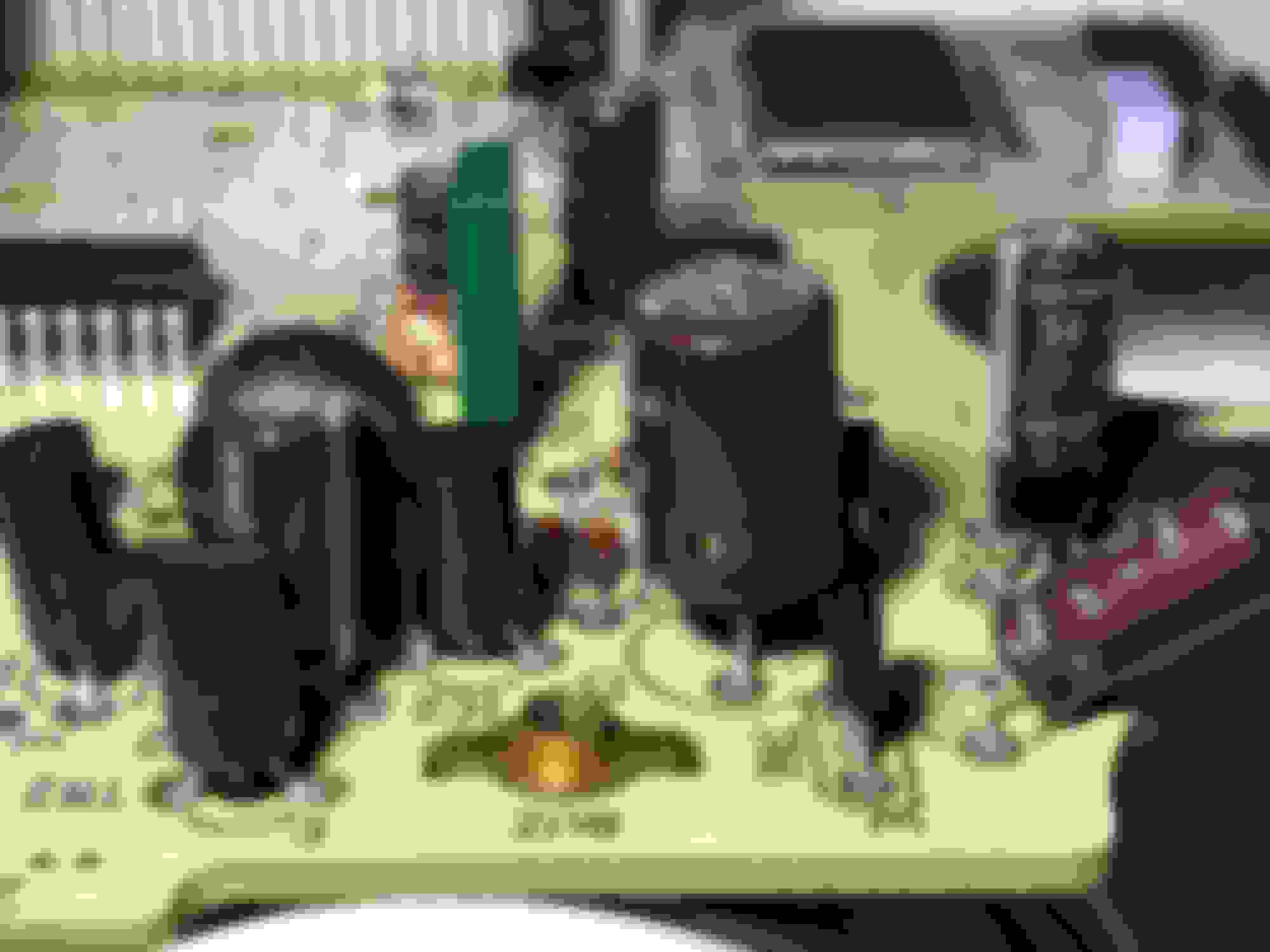
I have just removed all electrolytic capacitors, tried to clean and prep the top surface pads with fresh solder as the capacitors top pads even after removal nearly all had fairly obvious signs of what I assume is/was a resilient oxidation on the top surface of the solder that did not easy remove , and tried to clean up some of the trouble spots as well...
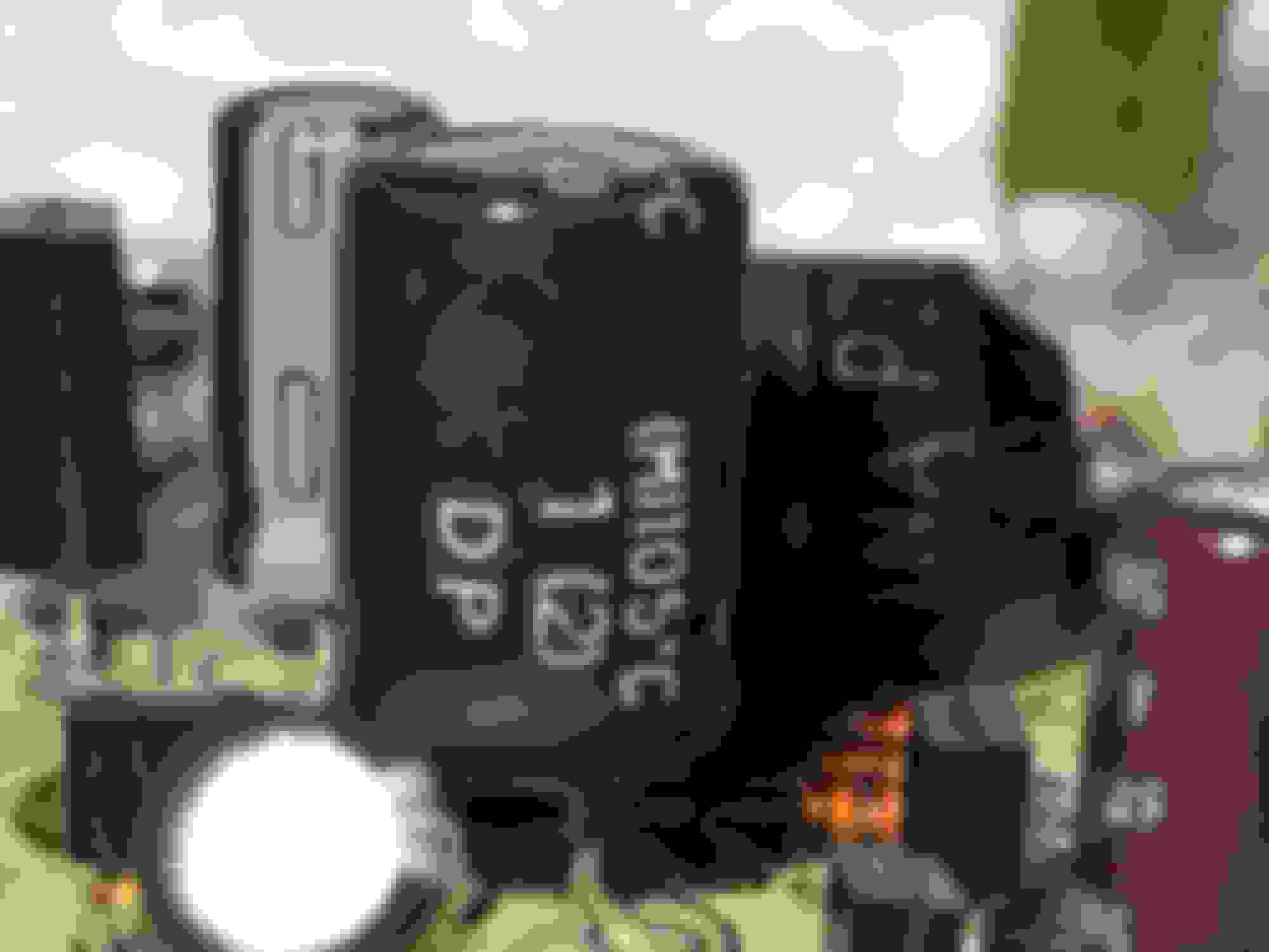
Each site seems to be clearly marked for polarity, save for one, C9
On C9, BP refers to the component being “Bi Polar”?
Polarity does not matter on C9?
Despite the component as received with Long leg (positive) is agnostic on site C9?
Are there any accommodations I should make before placing components into their new homes?
May I get any instruction you feel is helpful when placing these components, in terms of positioning, height above PCB or any other typical considerations that would be good to adhere to? Perhaps any not obvious pitfalls with placing capacitors to avoid?
Last edited by rotarypower101; Feb 27, 2020 at 09:09 PM.
For other Novices that may find this in the future, it took about 20 minutes to remove caps, with...multiple background distractions.
These are only my personal observations, they may not be strictly recommended…
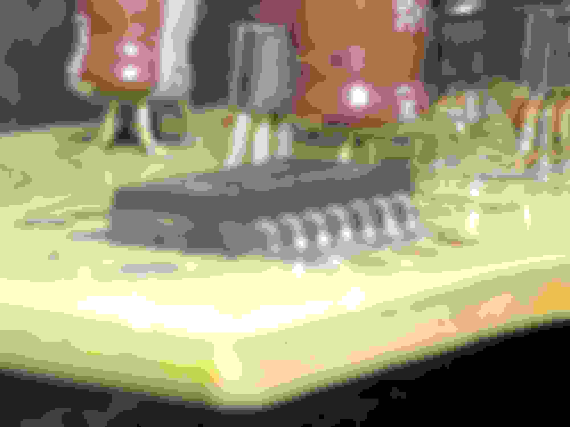
C9 is probably the hardest to remove for the combination of small component, and a broad wide possibly a “ground plane” as it draws in the heat. It may be advantageous to simply cut the legs long and work with the legs individually rather than the whole component if you are having difficulty. I did manage to get it out in 1 piece, but it was a consideration I had.
C16,C17 are only moderately difficult because of small size, use light prying pressure if required. But be Careful not to add pressure if not completely molten, Do Not lift a pad or trace! I don’t believe it will be required to nip legs on these IMO.
Generally speaking they all "walked out" for me by applying alternating heat to the pads.
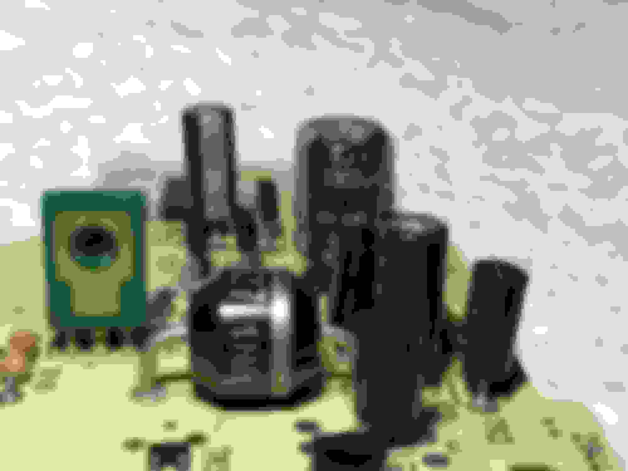
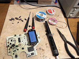
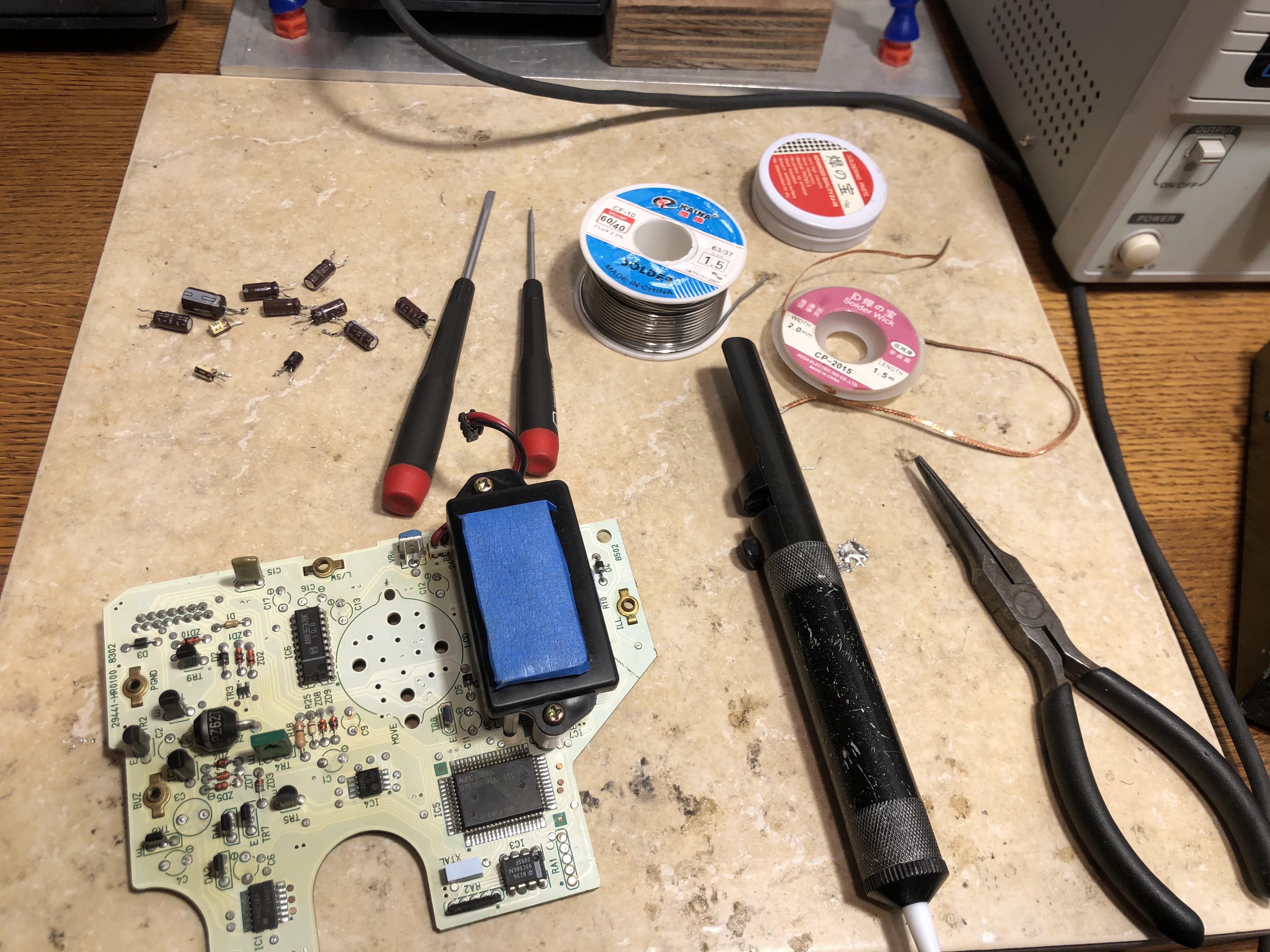
I used the tools pictured.
Solder wick, flux, solder, a solder sucker, side cutters, xacto, small flat head screwdrivers and a pair of needle nose pliers to grasp legs rather than the components when removing. (specifically because the legs of the caps appear to be “crimped” to create mechanical friction inside the through holes)
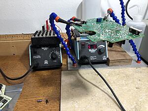
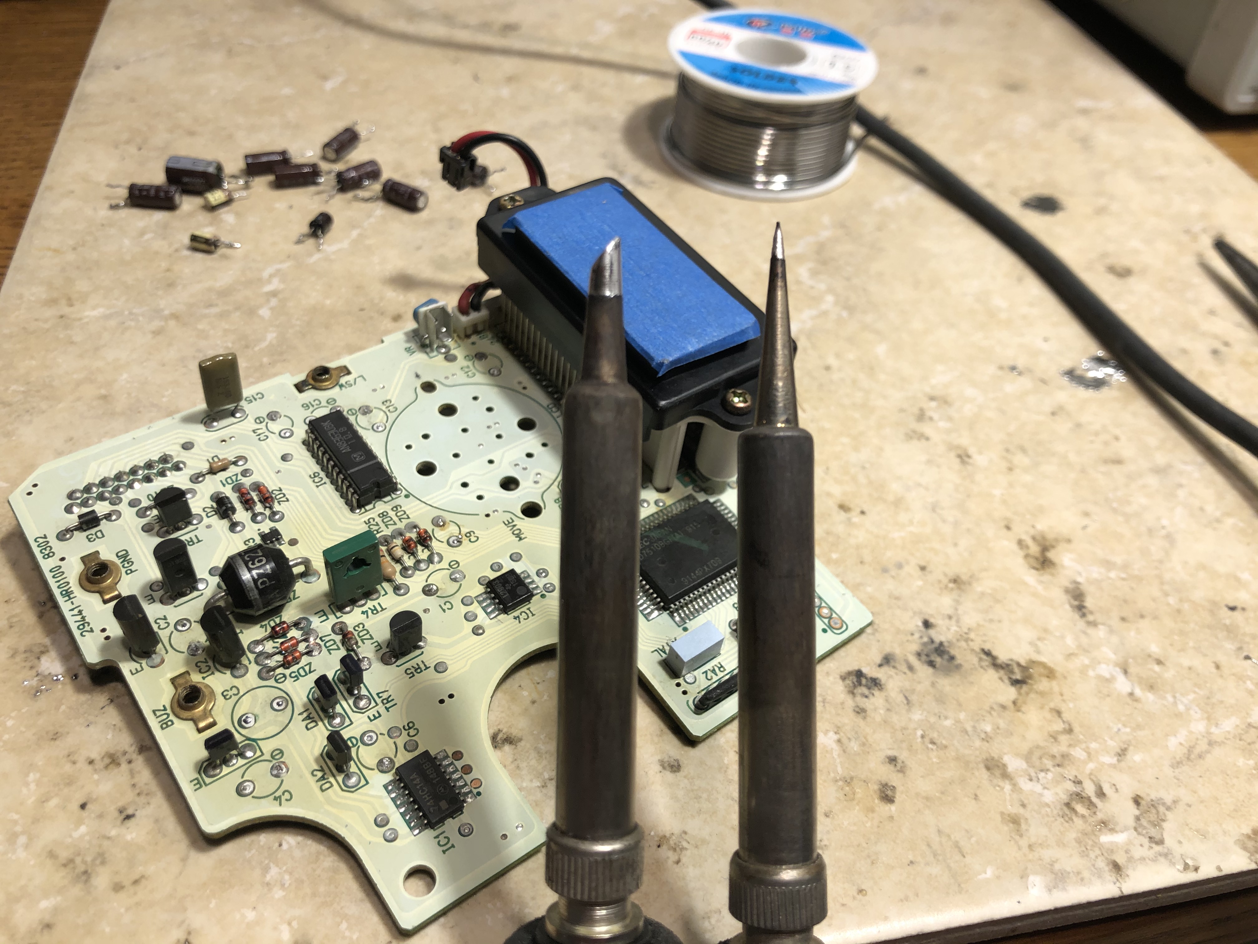
The solder iron I used Both a thick wedge and a fine tip on Both a Weller WES51 and a WESD51, again maybe not strictly recommended, but I found success at:
~500� for all but the broad traces, which I boosted to ~600� and kept the application as brief as was possible.
I also uses a DIY helping hand and PCB clamp to grasp the board
The Novice advice I would give is, don’t be afraid of it! But be careful, you can cause yourself a lot of grief if you are impatient…
If anyone that desires or wants advice from a non professional perspective, please feel free to PM me or post here.
Last edited by rotarypower101; Feb 27, 2020 at 09:51 PM.
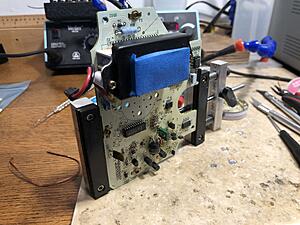
That was a good idea to place painter's tape over the LCD display. Just make sure the adhesive isn't too tacky. It may remove the paint on the black housing. I typically stick the tape along my pant leg twice then apply it to an object. That usually reduces the adhesive property of the tape enough to still stick but not enough to cause problems if left alone for a while.
Yes, you are correct. C9 is a bipolar cap so it doesn't matter how it is oriented in the circuit. As for the height of the replacement parts, I don't have a hard and fast measurement. I normally reference adjacent components and roughly eyeball it from the removed component.
I offer this helpful hint when installing replacement components: Bend one leg of the component after it is placed in the eyelets. It doesn't have to be a 45* or 90* kink. Just put enough of a bend on the leg so it will remain in place. Then solder the opposite leg. Once the opposite leg is soldered, then straighten out the bend and solder the remaining one. This should keep the component from moving wildly. After both legs are soldered in place, cut the tails off at the peak of the solder joint.
Also remember to use flux and apply solder from the backside of the board. The flux will allow the solder to quickly flow through the eyelet and ensure a good electrical and mechanical bond. A good solder joint should look like a mountain peak on both sides of the eyelet. This circuit board really requires solder to be on both sides of the eyelet because some components need contact across the entire eyelet (some eyelets have solder runs on both sides of the board). Lastly, do not bend the components after they are soldered onto the board. They need to stand straight up and the bend puts undue stress on the component. For example, IC2 looks like it has a serious bend to it. If you try to bend it back then it may cause a break at the base of the device (not at the base of the solder joint).
One final thought on soldering the legs into position: Use the double-bend approach to passing each leg through the eyelet. This will ensure that the solder fills the eyelet and surrounds the leg evenly.