When you click on links to various merchants on this site and make a purchase, this can result in this site earning a commission. Affiliate programs and affiliations include, but are not limited to, the eBay Partner Network.
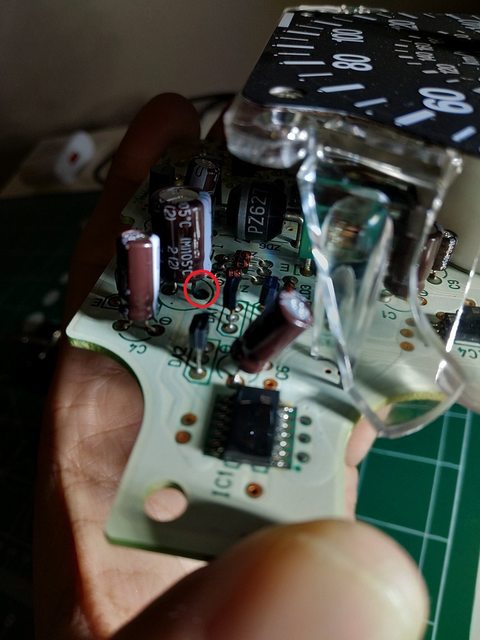
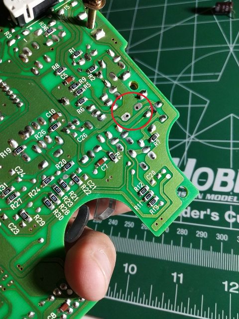
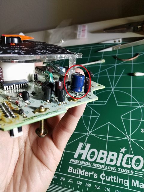
This top-down angle gives a good overview of the speedo board. From this angle, C3 is damaged and needs replacement. However, more components may have hidden damage at this angle. Please post more photos from different angles of the other capacitors. Refer to the other photos in this thread as a guide. Would you please post a photo of the backside of your board? I want to verify the 4 eyelets are ok from de-soldering the speedo face.
Copy, odo is only affected by the bad component(s).
The photos are too dark and casts shadows to make out any details. Get some close-in photos of the capacitors and use a flashlight to help eliminate shadows. For example, focus on a small area like C1 & C9. Then move to C3, C4, & C6, etc... Do your best to capture the full height of the capacitors - from the solder joint to its top. Look for anything that appears stained, charred, discolored, or crud. There are other examples in this thread for you to get an idea of what to capture.
Run isopropyl alcohol+cotton swab over the 4 eyelets. They could be damaged but I'm not sure. How did you remove the solder from these joints? What soldering equipment did you use? How much experience do you have with electronics soldering? I have a link in Post #47 that discusses general soldering tips and tricks. Please read it and ask questions before attempting to repair this board. It will not make you an expert overnight but it would reduce the possibility of user-induced damage during the repair.
That is good news to hear and see! I am glad to lend a hand. However, it would have been better to see and document the steps in between. I'm sure you wanted to "finish the race" but please tell us more about your journey! Your circumstances may help others in the future; much like others (like me) helped you. For example, do you have any photos of the newly installed C3 capacitor? How did the solder look between the back and front sides of the board? Also be mindful that replacing C3 may fix the problem initially but over time, the odo may blank out again. That would mean other capacitors (and/or the same one) would have to be replaced. How did the solder look after installing the speedo face? I expressed concern about the 4 eyelets in Post #129. What about documenting your experience with soldering or remarking about the equipment used?
Sorry for the delayed reply. I am glad to see that the flex print schematic helped your problem. This jumper you installed is a temp fix; please do not make it a permanent fix. You must also be very cautious to isolate the wire between the 2 screws to avoid short circuits. If you saw +12V at Connector C1-01 Pin 4E and low voltage at the Tach Pin then that indicates a problem with the Speedo Board and/or the flex print.
As you were diagnosing this problem, did you remove the Speedo board and inspect it? Did you see anything unusual? Remember, the Tach gets its signals from the Speedo board. Did you visually inspect the flex print for any breaks in the run between the Speedo connector (Con1) and the 3 screws? The bend at the Speedo connector would be the weakest point. You could also have some damaged/leaked capacitors on the Speedo board that may require replacement.
What ECU do you use that causes the Tach to "wake up" and sound the over-rev buzzer?
Cheers,
George
George, apologies for the even more delayed response; answers (as best i can) to your questions below:
1. I did remove the speedo board and made a few repairs however i thought i had repaired anything that seemed less than acceptable.
2. I dont remember seeing anything that looked like it would be causing issues.
3. I use a Link G4 ECU.
I have also noticed that since my "fix" the dash power (and i believe ECU also) remains on even after i turn the key off. I will be removing the dash again when i get the time, hopefully this weekend to inspect further.
No worries on the delayed response. Thanks for answering those questions I had. After reading your newest post, I have a few more questions to ask:
1. Do you remember what was repaired on the speedo board?
2. Did you take any pics of the board - before and/or after?
3. How is the Link G4 ECU connected to your car; where does it get power?
4. Does it (ECU) send a tach signal out and where does it go?
5. Does the ECU have some sort of Vehicle Speedometer Sensor signal?
6. Does the "fix" you mention refer to the +12V jumper wire to the tach screw?
I suggest removing that jumper wire before troubleshooting any electrical problem in your cluster. This would allow you to measure the inputs/outputs from the ECU and to other components, like the speedo.
Wasn't sure which Odometer thread to post to, so I figure I'd post into this one. Big thanks to all threads around to helping fix this.
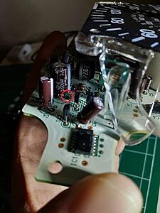
I didn't want to remove the speedo unless a component was broken and I had to lift it out of the way to repair, so I took a flashlight and went over every piece for a while to see which ones were leaking. I could only see C3 leaking, and it didn't even leave any spots on the board, I could only tell from the leg being rusted up and not shiny anymore, it's a little hard to spot in the pic.
Went and desoldered it and removed it from the board and installed a new one from digikey.
Woo! Working odometer again! Thanks for all the info from these 3 threads!
Last edited by RapidCancel; Feb 11, 2019 at 11:05 PM.
You are welcome that these threads helped you troubleshoot and repair your blank odometer! I'm not sure if my browser is acting up, but could you verify 3 of the 4 photos you posted? I see an error message for them that say, "The image you are requesting does not exist or is no longer available."
If the odometer blanks out again then you may need to replace a few other capacitors. It may be harder to identify which ones need replacement. C3 is typically the one that members could easily identify as bad. How do your solder joints look on C3?
Gen2n3 - Not sure what happened there, but I've reattached all the pictures for you, so hopefully that works.
I actually went and bought quite a multiples of a few other capacitors with my order since I was already buying C3, in case they went out in the future. The new solder joints look pretty good, I haven't put the cluster back in yet. I was planning on taking everything apart and cleaning it up a bit before putting it back in, so I'll take it out and snap a picture for you tomorrow.
Thank you for reloading the photos. I've noticed lately that some photos would hang during the upload process. Sometimes I have to reload it multiple times just for it to post properly.
It sounds like you have things under control with capacitor replacement. Are you skilled at soldering? If you'd like, you may post close up photos of the solder joints and I could offer some advice. Briefly, the solder joints should look like mountain peaks on front and back sides of the capacitor. The solder should be shiny; if it looks grey or solder did not properly flow through the joint then it could be a cold solder joint.
I just have a small question, what can be done if the LCD display of the Odometer itself is bad? is there a replacement that can be sourced and re-soldered in? or will I have to procure a new cluster?
Gen2n3 - I do have some experience with soldering, mostly when I used to play with some RC cars and soldering some keyboards together, and then minor things like wiring stereos up. My solder joints do look like mountain peaks and they looked good to me, I'm generally pretty picky so I like to take my time to get things right. Thanks for the tips.
To answer your question, the LCD display could be replaced. It would require desoldering all 46 (23 per side) contact points then installing a replacement. As far as I know, there are no known replacement LCD displays therefore one would have to cannibalize a display from another speedo. Naturally, a new speedo board would solve the problem if one is willing to spend the money.
To answer your question, the LCD display could be replaced. It would require desoldering all 46 (23 per side) contact points then installing a replacement. As far as I know, there are no known replacement LCD displays therefore one would have to cannibalize a display from another speedo. Naturally, a new speedo board would solve the problem if one is willing to spend the money.
Do you suspect your LCD display is bad?
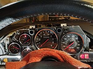
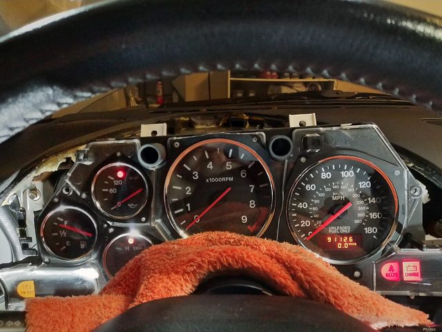
They say a picture says a thousand words... =)
I'm pretty sure this display is shot, but I also suspect that there may be underlying issues too that might show up after it's been replaced.
The display doesn't look good but the unusual characters may indicate a problem with the speedo board itself. I would recommend that you remove the instrument cluster, remove and inspect the speedo for leaked capacitors or other damaged components. Please share your findings when you decide to open up your instrument cluster.
I had a similar thing happen to my odometer several years ago. Only a few of the LCD's lines worked and the numbers were unreadable. It was not the display but the odometer portion of the circuit board had a bad cap, just like all the other bad caps on these boards. I believe if you fix the caps, the display will probably be good. IMO, I would try that first.
Mike
Sorry to hear that your odo fix was temporary. What capacitors did you get in addition to C3? When you remove the board please share some photos of it. You may need to inspect the legs of the components around C3 where the electrolyte leaked. That acid may have eaten away at some of the solder unless it was neutralized. Please, keep us posted.
Sorry to hear that your odo fix was temporary. What capacitors did you get in addition to C3? When you remove the board please share some photos of it. You may need to inspect the legs of the components around C3 where the electrolyte leaked. That acid may have eaten away at some of the solder unless it was neutralized. Please, keep us posted.
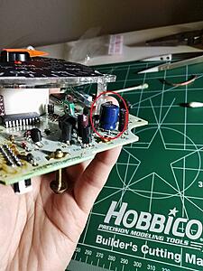
I looked through the board and I bought every capacitor that was starting to tilt, I had about 3 or 4 of them that were already tilting, so I figured they would have to be replaced eventually. Honestly, I should have just replaced them then, but I really just wanted the odometer up and running again and those would have required me to desolder the speedometer gauges, which I didn't do to replace C3. Is there an easy way to see if the acid had eaten the solder? Does the solder actually get removed? When I first pulled it to look at it, the acid hadn't gotten to any other components.
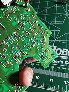
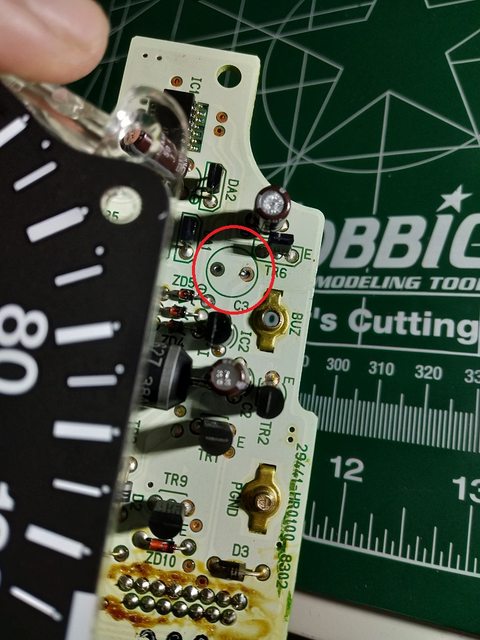
Welp, seems like I fucked up. Had no problems the first time I replaced C3, but I went to replace it again and it looks like the plated through hole copper (eyelet) came out with it. Any suggestions on what I can do? Can I still just solder the new capacitor on there without the plated through hole copper? I should just be able to solder on both sides of the legs for the capacitor right?
Last edited by RapidCancel; Mar 21, 2019 at 11:34 PM.
Damage to an eyelet (barrel) is never a good thing. Typically, the eyelet is attached to the copper run underneath the solder mask (either the white or green mask). When the barrel is pulled from the board then the copper run is severed. It sounds like too much heat was applied to the solder joint and/or the leg of the capacitor was still connected to the eyelet when it was being removed. Take some photos, especially up-close and personal photos of the eyelet and socket. There may be a chance that it could be saved. Otherwise, you may have to epoxy the barrel in place then run a jumper from the capacitor leg to the trace that was broken. If this exceeds your scope of expertise then I would recommend finding a local electronics tech who specializes in micro-miniature component & board repair.