When you click on links to various merchants on this site and make a purchase, this can result in this site earning a commission. Affiliate programs and affiliations include, but are not limited to, the eBay Partner Network.
Mike, copy all. I don't know the phone that you use but if your cell phone charger has a detachable cord then you could detach it from the wall wart. Plug the cable into your USB port (if it has a USB Type A plug) then the other end into your phone. Your computer should then recognize a phone is attached. You would then navigate to the photo directory, usually named "DCIM". Do you have someone at home who is more tech savvy?
On the original problem that occurred for years
one thing to clarify the tach does not bounce around.when its acting up.
If say I was cruising at 2500rpms, it will jump up to 3500rpmz and stay there for sometimes up to several minutes. ( and will stay incorrect getting farther off at higher rpms)
Sometimes it may only read incorrectly for several second, othertimes quite a while...
Hope to do some troubleshooting and testing this weekend
Have you found anything with your instrument cluster problem? Did any of my recommendations help?
I ended up sending the cluster back to Geoff, and he ran it on his bench for a while and it started acting up, and he said he was pretty confident he found the problem. He wont specify what part it was though. But said he put the bad part on a seperate cluster and it caused it to behave the same way.
I've got the cluster back and will see if it holds true or not this weekend.
Hi George, Sorry for the delayed response. I have taken some pictures along the way. The Odometer failed end of last summer so I garaged the car and took care of other burning issues in my life. Time has rolled on and now I need to smog the car in August. I know they want to check mileage when that wonderful process occurs. So I'm under that gun to get this resolved. I have started the desoldering aspect and expect to complete all the work myself. I used to be pretty good with an iron back in my war days. But the eyes are getting old and the hands are no longer 20 something steady. so it will be a fun challenge. I live in fly over part of CA so not a lot of rotary activity around here. Currently I have three irons of various wattages. Had to toss my 40 watt unit recently as it was falling apart. all others are lesser wattages.
Hi George, I'm retired tech. I just miss my command line interface approach. Apple is a closed environment. I need to fake out my PC to have Apple think its one of them. This is actually familiar to me as I was a DEC tech which was another closed environment. My phone is iPhone 7 running iOS 13.5.1, my PC is a laptop Dell running Win 8.1, I have refused to upgrade the OS, as I see no pressing reason to keep on that merry go round . Had the disk drive swapped out for a RAM disk last year. Seems to run fine. I prefer a laptop as I travel a bit.
Just need to get the Apple environment faked out on the PC side as I understand it that means getting some feature in Apple Tunes loaded into my Windows environment so Iphone thinks its communicating with another Apple. Then of course there is the file structure that probably needs to be replicated. On my Iphone my picture library is broken into 4 subdirectories. It would be sweet if Apple takes care of this during the gross "copy all" but knowing my luck with computers and life in general, I may have to manually construct that too ahead of the bulk transfer. So pictures will come but not immediately.
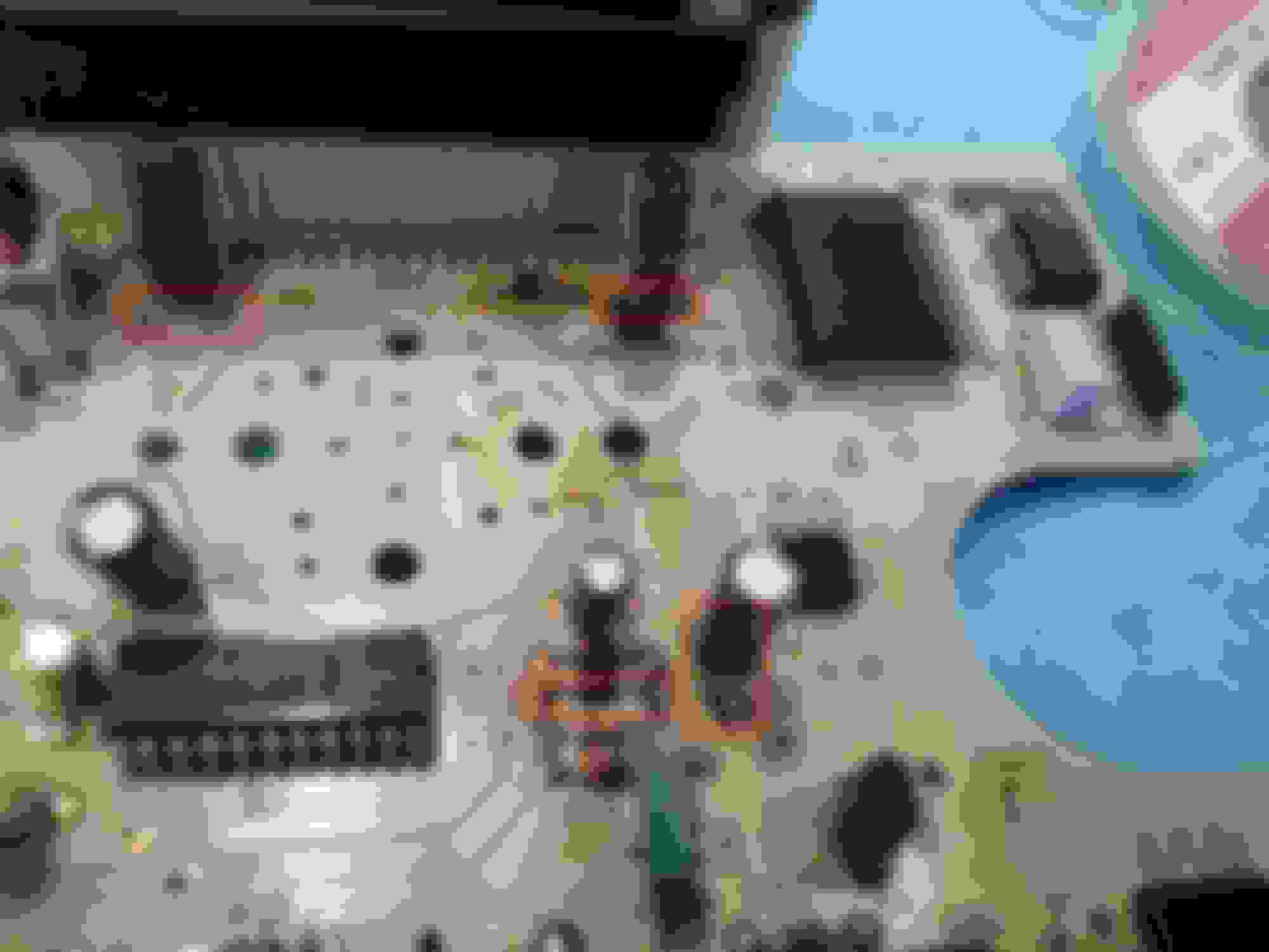
My board had very little damage beyond C3. TR7 base solder weld was darkened. DA1 above TR7 was also darkened but both cleaned up nicely with IsoPropyl. Same with the three Zeners next door. I did a general clean up all over the board getting most of the yellowish like "smoke staining" off the board. The back side showed hardly any discoloration except the bottom of TR4 (the green transistor unit with the hole in its body.
Some background, I left the USAF and civil service in 1974 but stayed in USAF Reserves, Spent the next 5 years at National Semiconductor, then 8 years at Intel, then 2 years at LSI Logic followed by a short reprise back at National, then the next 15 years running my own mainframe computer management contracting business specializing in the semiconductor world. Linear Tech, Integrated Device Tech, Sierra Semiconductor, Siemans, Altera Semiconductor, Xicor Corp. Chartered Semiconductor (Singapore) where some of my contracts. Saw a lot of chips manufactured. Was involved from mask making, fab, assembly, test, boxstock and marketing, walked a lot of factory floors and computer rooms in that hayday.
Nice to see Nationals, presence at IC3 the E2PROM in a DIP plastic package no less. where our mileage is carefully saved, I hope.
.
Wow! That's quite a career path! I wish I could help with the iPhone photo extraction process but I do not partake in Apple products. As you pointed out - they are a closed environment.
If the board sat for about 1 yr then there should be all sorts of gooey gunk running down the length of the board. Be sure to inspect the leads of each component for proper contact. I've seen some broken legs at the body because of the leaked acid. Yes, IC3 is where the mileage is stored. What does the solder joints look like on TR4? It sounds like you did a good job neutralizing any acid and dried flux from the board.
Don't be surprised that the other capacitors failed, like C4 and C6. You may also be better replacing all electrolytic caps to ensure the speedo board is within limits. I'm standing by for those photos!
My last tour in the Navy was in Lemoore, CA. It's tucked away between Fresno and Visalia. It was interesting. I was an Avionics Technician, retired in 2016. What do you know about transistors and transistor theory? Mind if I pick your brain offline?
I too was an Avionics tech - C5A and C141 at Travis AFB in the early 1970s. I did 2 years active then 20 years Reserve. My Reserve military career ended in Nov of 1992. I never left Travis. I quit working in 2004. Now just a pensioner.
Brain picking is fine anyplace anytime. But I would advise you to keep your expectations pretty low. My knowledge base originated in the dark ages of electronics I still have my father's slide rule, and some of my early calculators - an HP 21 and two Novus 4515 and 4615 all based on RPN. Dad designed vacuum tubes during WWII then migrated to Stanford where he built radio telescopes and later worked the power electronics for SLAC. He tried to teach me about transistors back in the late 1950s or early 1960s. I studied some in college too, late 1960s.
"What does the solder joints look like on TR4?" TR4 lost some solder on the Emitter leg. All three legs look and feel solidly attached. I'll probably attempt to resolder all three legs starting with the emitter leg. C4 and C6 cleaned up but probably also should be resoldered. Some solder to TR7 collector pin as well.
Not much fluid damage that I can see especially after cleaning. But the vertical flow pattern was obvious. and I will concentrate my resoldering efforts in that general area. If it doesn't test well, then my guess would be to replace C4 cuz it nearest pin showed acid black on it before cleaning. The can looks solid and both legs seem well attached though. The Zener diode Z05 also lost most of its solder on both legs. Yet still seems well attached. So later this week I should have my first part to install.
I would advise not to replace the Zener diodes. They are fairly stout solid state components. I would strongly recommend to clean the areas with isopropyl alcohol. That will neutralize any acid that still remains from the capacitor leaks. I can see plenty of leakage too. Based upon the photos submitted, I recommend replacing certain capacitors, some of them may be replaced for a 2nd (or 3rd) time. I also see a lot of broken/cold solder joints, especially around ZD5, ZD4, and ZD7. The acid was the major culprit to those solder joints.
Here are my recommendations based upon the photos (see red highlighs):
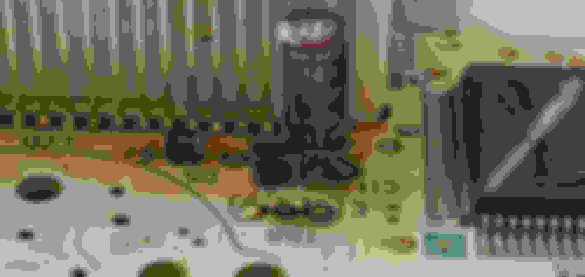
TR6 has a bad solder joint. Suspect all 3 joints are bad - recommend replace solder. There is a 2nd bad solder joint at ZD8 anode - recommend replace solder. Solder joint for C3 looks too excessive. Need a better angle. I would suggest replacing this capacitor again. It also needs just a bit more clearance off of the board. Clean area around C3 & DA1 with alcohol. Replace C6, it also has a bad solder joint. This capacitor appears to have a bulged top, which is a bad sign.
Recommend replace C11 and C12. These caps also appear to have bulged tops. This is a better view of ZD8. Note the missing solder on the anode (left) side. Solder needs to fill the cup from the backside of the board to the top. C1 has excessive solder. Clean the board around C1 too. There appears to be charring around that one leg, which could mean the eyelet is damaged. Use a DMM to read the trace from C1 anode (C1 +) to ZD3 cathode (ZD3 -). It should read 0 ohms.
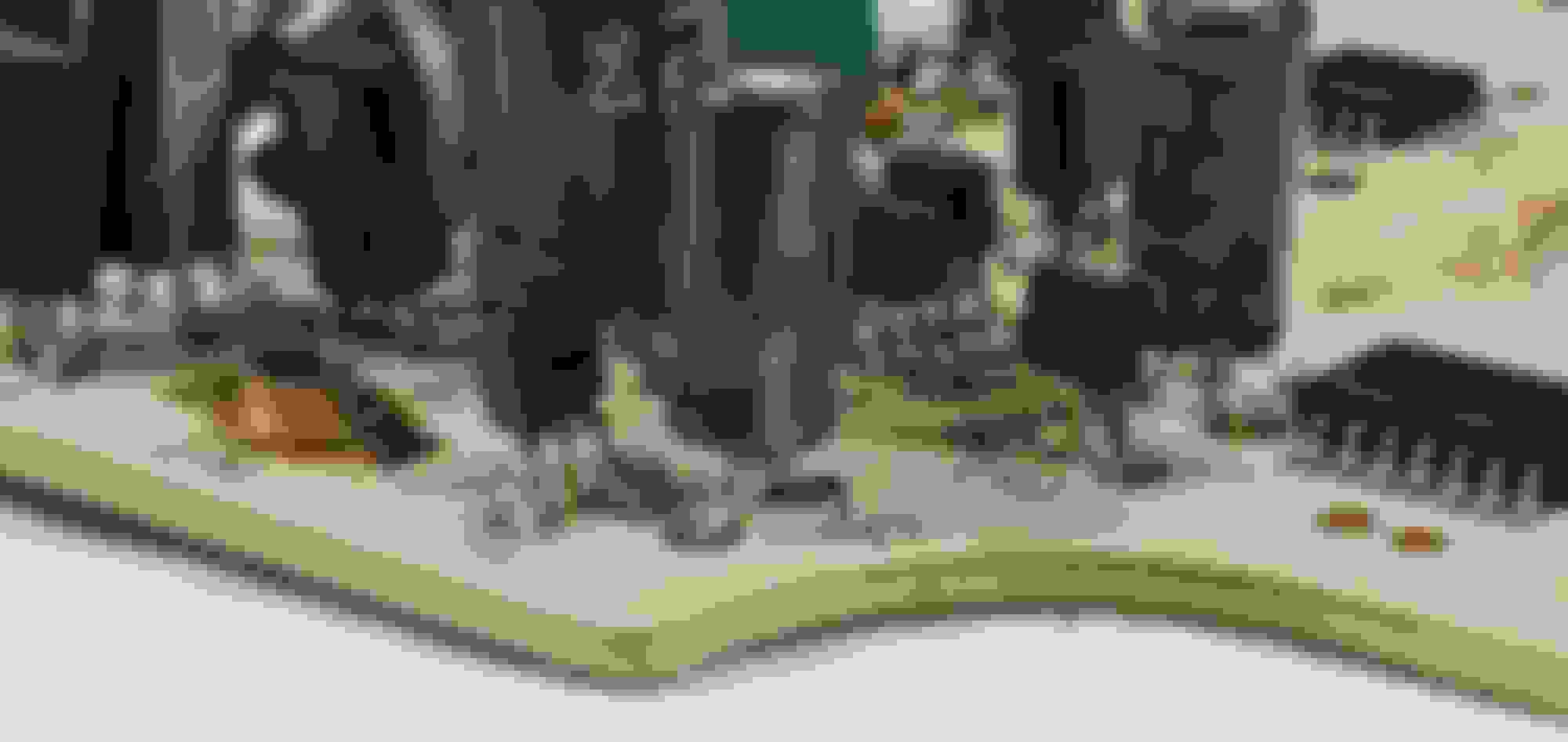
This is a better angle to show C6 has a bad solder joint. It also has a bulged top. C4 appears to be bad as well. Replace these bad capacitors.
Clean up the areas around C3, TR7, DA1, and ZD4, ZD7, and ZD4 with isopropyl alcohol. Recommend replacing solder on ZD4, ZD5, and ZD7. Replace solder on the ground plane first then replace the solder on the opposite ends of these diodes. This is a different angle that shows C4 and C6 with bad solder joints. Just replace these 2 capacitors.
I highly encourage you to check out another thread that I have which discusses some soldering tips & tricks. It should make soldering and de-soldering an easier task for a DIY project. Just remember, it will not make you an expert!
Does that help?
Gen2n3
Could you take a look at this pics and advise which components I should replace? I already removed the one in the blue circle which I know is bad, but not sure about the others.
@Milwgearhead, I moved your post to this thread to better discuss your repair options. What problems are you experiencing? Is it the blank odo or did you experience other issues with your speedo board? BTW, a loss of cruise control (seeking speed) is a symptom of a blank odometer.
You said that ZD3 (the blue circle area) was removed because you knew it was bad. Was it? Did the legs of ZD3 break? That charring that you see is actually leaked acid that oxidized. Clean the areas of the board with isopropyl alcohol first then post new photos. I'd bet dimes to donuts that C3 is the primary culprit of spewing its acid down the board. If that is the case, I would recommend replacing all electrolytic capacitors as an added layer of protection from future failures. I would at least replace the following: C1, C2, C3, C4, C6, C9, C11, C12, C13, C16, and C17.
Additionally, clean the legs of IC1 and IC4 then post pics of them (get up close shots). I'd like to check them for damage. Check out the other photos in this thread to give you an idea of what angles to take and help you spot potential problems. Pietrino had some great photos so you may use his pics as a rough guide.
Thanks George, my odometer went blank about 10 years ago, and more recently the speedo and tach needles began bouncing around erratically so I decided that maybe I should begin looking into this. I removed the ZD3 because it was completely black, and from what I read on other posts is to look for blackened components and replace those. The pictures I posted were taken after I cleaned the charred areas with QD electronic cleaner and a q-tip, let me know if you need them any cleaner. Here's the new pics, I hope they are clear and the correct angles.
@Milwgearhead, I moved your post to this thread to better discuss your repair options. What problems are you experiencing? Is it the blank odo or did you experience other issues with your speedo board? BTW, a loss of cruise control (seeking speed) is a symptom of a blank odometer.
You said that ZD3 (the blue circle area) was removed because you knew it was bad. Was it? Did the legs of ZD3 break? That charring that you see is actually leaked acid that oxidized. Clean the areas of the board with isopropyl alcohol first then post new photos. I'd bet dimes to donuts that C3 is the primary culprit of spewing its acid down the board. If that is the case, I would recommend replacing all electrolytic capacitors as an added layer of protection from future failures. I would at least replace the following: C1, C2, C3, C4, C6, C9, C11, C12, C13, C16, and C17.
Additionally, clean the legs of IC1 and IC4 then post pics of them (get up close shots). I'd like to check them for damage. Check out the other photos in this thread to give you an idea of what angles to take and help you spot potential problems. Pietrino had some great photos so you may use his pics as a rough guide.
Also, do you know the part number for the ZD3? I can't seem to find that one.
Thanks for posting the photos. Wow, your odo was blank for 10 years? I'm surprised there isn't more damage to your board! Despite using the electrical QD cleaner, I strongly encourage you to clean the board with isopropyl alcohol and an old tooth brush and/or cotton swabs. That will actually clean off and neutralize the acids slowly chewing away on your board. The brownish goo that is visible around the LCD screen is old flux. It is mostly harmless but it can be removed with some light elbow grease and isopropyl alcohol. The blackened goop and green discolorations are a combination of acid eroding material and copper corrosion. Again, the alcohol will clean and neutralize that stuff. Do not be surprised when you clean the board and see the solder mask (white top coat) peel away. If that happens then you can seal the damage with clear coat nail polish. But only use the clear coat at the final stage of board repair. That is, if you decide to repair the board yourself.
Unfortunately, I have bad news about ZD3. No part number exists for it.That is why I asked about its removal. I recommend removal of any Zener diode only when it has been physically damaged. Like it absorbing too much current and explodes or a leg was severed. Zeners are fairly robust so the blackened/charred deposits you spoke of may not have damaged that diode. Do you still have it? BTW, Zener diodes require a unique test method to determine its forward and reverse bias voltages. You simply cannot use a DMM to test it.
IC1 does not look bad, so that is a plus. Please clean the legs of DA1, DA2, and the surrounding TRs (include IC2, please) with a cotton swab/acid brush and isopropyl alcohol. Then take a few more pictures of the legs on these components. I'd like to see if the legs are damaged by the acid. Pay special attention to the area where the leg meets the body of the device. I have an example of acid that chewed away a transistor leg. It was only visible when viewing at a very low and close angle. For example, take a hard look at TR5. There is blackened goop at the body/leg union in that photo. Additionally, be careful not to wiggle those components because that may cause a weakened leg to break! I also believe Pietrino had a few photos that showed acid that ate at one of those legs. IC4 may have a problem with cold/broken solder joints. In the last photo, I see the 3rd leg (2nd from the right) is a dull grey and lacks solder when compared to the other joints. I recommend re-flowing the solder along that side. Be careful though! IC4 is a surface mounted device (SMD) and a traditional soldering iron will easily damage the pads on the board and legs on the chip. That solder issue could also cause problems to your tach and speedo. Previous research indicates IC4 is a double comparator circuit that processes tach and speedo signals. Either that could cause your bouncing tach & speedo or the more probable cause could be a poor ground.
Have you seen my Speedo parts thread? It is found here: https://www.rx7club.com/3rd-generati...-only-1112010/ It lists all of the parts that make up the speedo board and provides part numbers for most of the components. Diodes and Zener diodes are an exception.
Your bouncing tach could also be the result of cold solder joints on the IC1 chip on the tach itself. In order to see both sides of the IC1 chip on the tach, you will need to remove its face.
Yeah, the odo has been blank for a very long time. At the time I didn't care because never intended to sell the car, and I only drove it a couple hundred miles a year. But now I want the car perfect again. I do have the ZD3, but one leg is broken. The ZD3 sounds like it's going to be a big problem, without it I'm dead in the water. Any ideas where I can find one? I was using the QD cleaner because finding 99% isopropyl alcohol locally is impossible with every using it for sanitizing. I'll just order it online. I also was very nervous about damaging the board with aggressive cleaning and over saturating with chemicals. Are they more durable than I think?
I did see you speedo thread, that's where I found all the numbers for the capacitors.
Thanks for the addtional info. When I get the Iso in I'll clean the areas you spoke of and post new pics.
Copy all. Thanks for the thread compliments! You can use anything above 70% iso alcohol without any issues. You can also use denatured alcohol. Denatured will evaporate much more quickly.
Regarding the Zener diode, we are venturing into uncharted territory. And sorry to say - yes, you are dead in the water without ZD3. I have only speculated possible replacements of such unobtainable diodes. Take a look at this link Flex Print Components Post #7. It is for a proposed replacement for Zener Diode D8 on the instrument cluster flex print. The post has a specification sheet with a highlighted part number. If you choose to use that part then please remember that is for a different circuit and it may not work or cause damage to another section of the board. I would not be surprised that the board would require many repairs to get it working properly. Sadly, time was not kind to this board. All the research thus far has been exclusively academic and based on external observations. On the positive side, I have seen boards in far worse shape.
The alternative would be to buy a new speedo board. That's like throwing the baby out with the bath water. You will never know what fixed your speedo board but you also have the benefit of the board working without failure. Given the extent of damage to your board, that could be a viable option. Your current speedo board may not work after replacing all electrolytic capacitors, replacing ZD3, and reflowing the solder on IC4. There could be other gremlins lurking about that I haven't spotted yet. You could give Ray Crowe a call for speedo availability. Even a JDM speedo will work (one or two resistors would have to be moved though). DaleClark has an excellent KPH to MPH speedo conversion thread that you could reference.
That gives me a few options to find a new one, those leads will help. On the otherhand, I really have nothing to lose by trying to use the D8 . . .I guess it can't get anymore broken.
Thanks for the help and I'll let you know what happens.
Hello... I just got my FD not long ago and sorry if this is not the right place to ask... but is there any way I can replace the LCD odometer display? Mine seems abit cracking or maybe due to caps going bad and leaked? Does anyway know where I can get the screen itself? I tried quoting stock part, stopped production. Knight sports also stopped...
I see that you are a new member, welcome to the forum!
The LCD display is a robust device when compared to other components on the board. There are no new LCD screen replacements for the speedometer. If the screen appears to be cracked then chances are the polarized film is crazed. Take a look at this post in a similar speedometer repair thread here: Post #285. Read the thread from Post 285 until Post 293.
I strongly recommend inspecting the capacitors on your speedo when it is out of the instrument cluster. Check for leaking capacitors and/or replace them now before it becomes a problem later. Capacitors C2, C3, C4, and C6 are the most prone to fail.
Yeah.. I have seen that post a from a while ago.. and was hoping someone would have found out which LCD it is and can be replaced. I guess I just have to do the polarizer film repair. I also noted the cap failing bits and maybe will do it all together. I have the 1996 type 4 JDM which is the lowest produced variants... nothing is ever in stock or already stopped production.
I have had the car for 6 months maybe need to do more reading on this site.
So I've been trying to troubleshoot the speedometer on my FD. Odometer and trip odometer work perfect and show correct mileage but as soon as accessory power is turned on the speedometer will sit at 55mph. when power is removed it will go back to 0. Power FC shows correct speed. Replaced all caps on the board as well as reflowed all solder joints. I'm guessing it is an issue with IC6 as it looks like it is the driver for the stepper motor. Speedo does work fine with another cluster. Any help would be awesome.