When you click on links to various merchants on this site and make a purchase, this can result in this site earning a commission. Affiliate programs and affiliations include, but are not limited to, the eBay Partner Network.
Would you mind if I looked at your USDM speedo? I would like to study it, repair it if possible, and potentially return it to service. If interested, PM me!
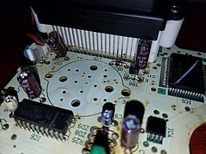
Get a q-tip and rubbing alcohol to clean up those solder joints. It was a little hard to see what was bad from my phone. If possible, could you edit the pics with red circles to highlight some of the potential problems? Take more pics as needed too.
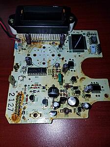
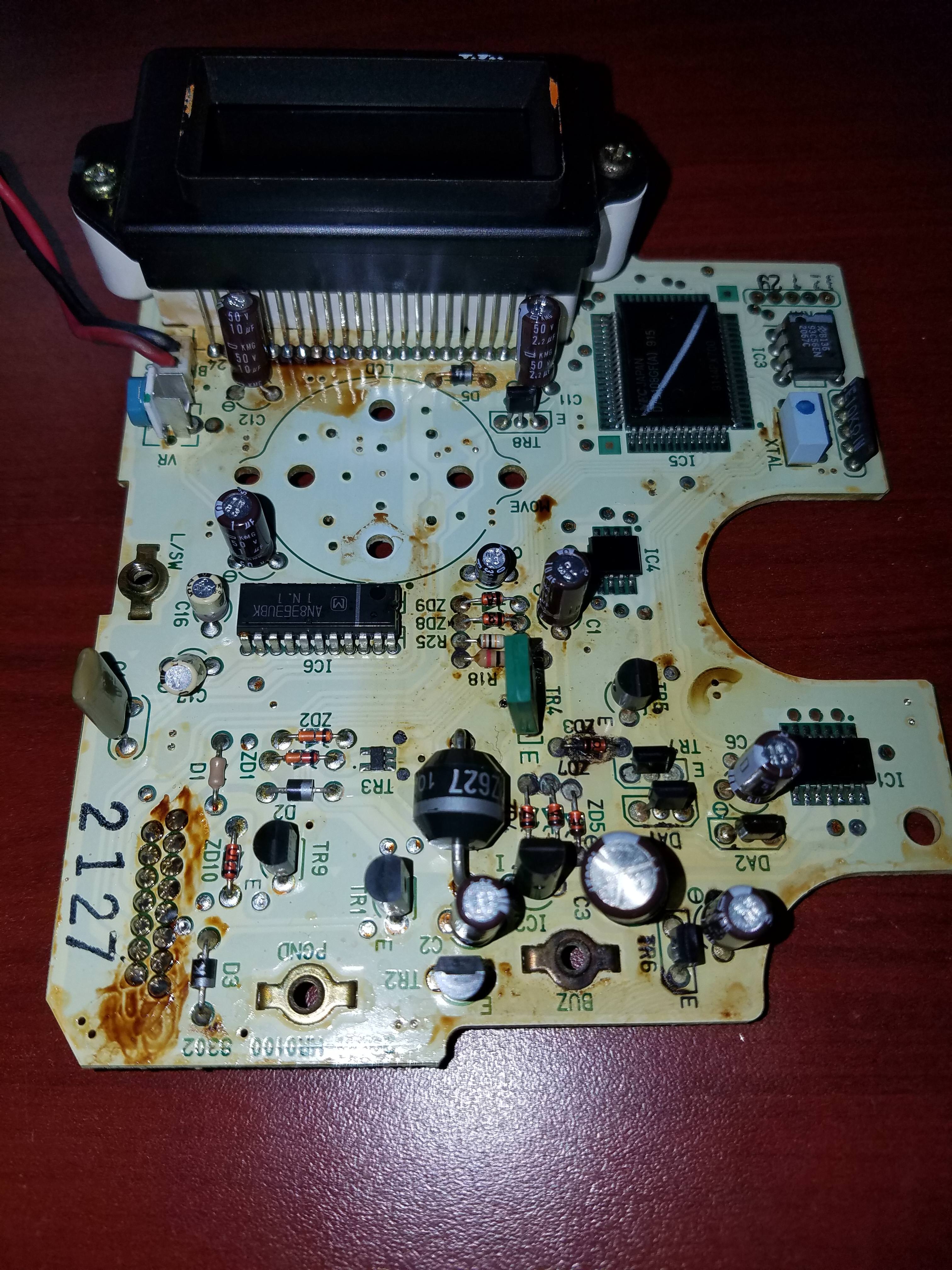
From what i could see, the electrolyte leaked from C3 and caused some dark spots along the other components.
I will have more time tomorrow afternoon to review your pics on a computer screen.
Get a q-tip and rubbing alcohol to clean up those solder joints. It was a little hard to see what was bad from my phone. If possible, could you edit the pics with red circles to highlight some of the potential problems? Take more pics as needed too.
From what i could see, the electrolyte leaked from C3 and caused some dark spots along the other components.
I will have more time tomorrow afternoon to review your pics on a computer screen.
Thank you for the initial post!
Cheers,
George
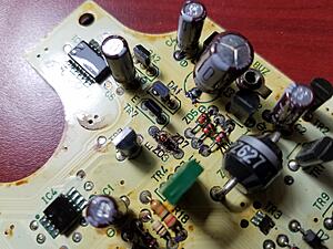
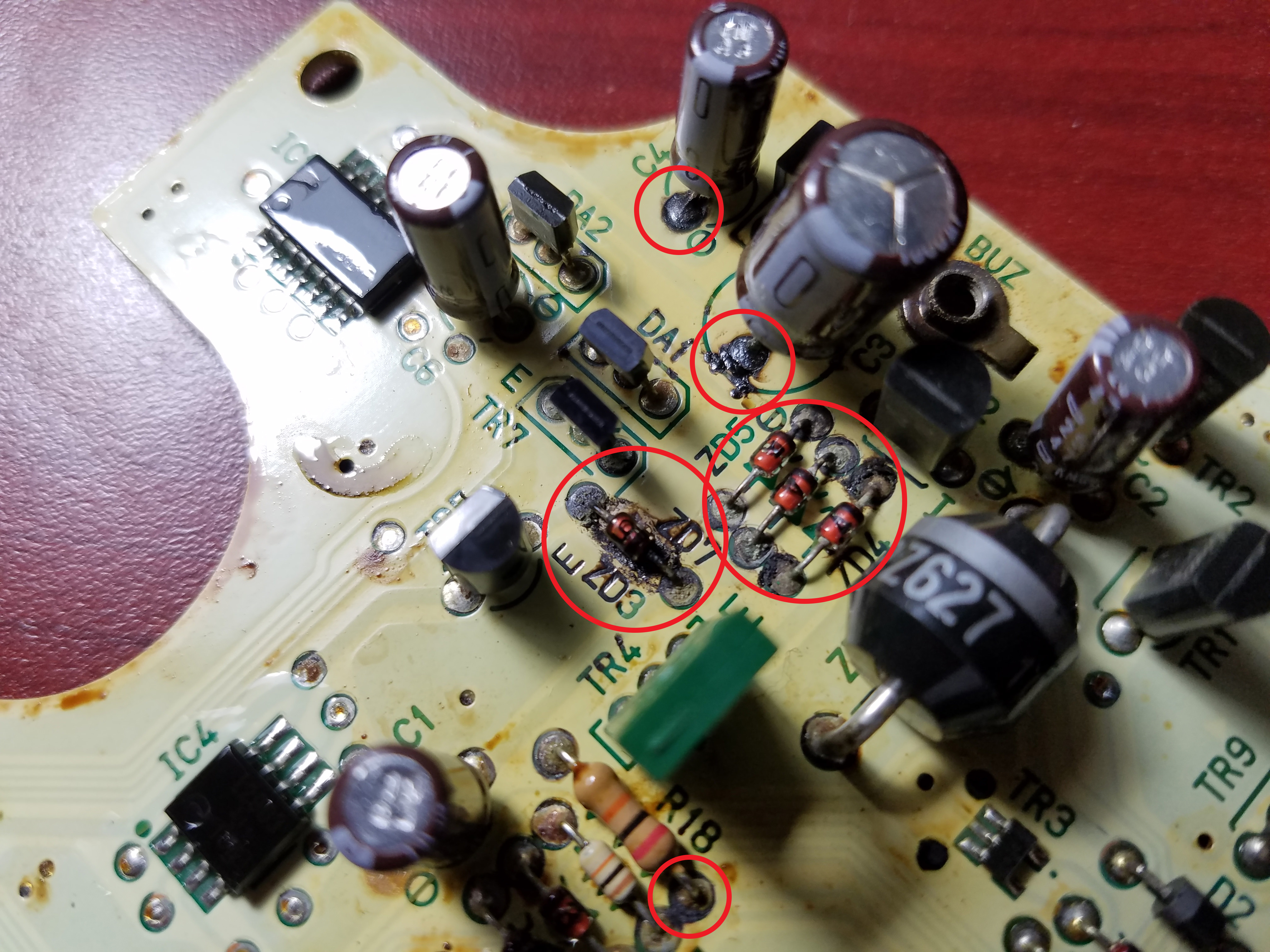
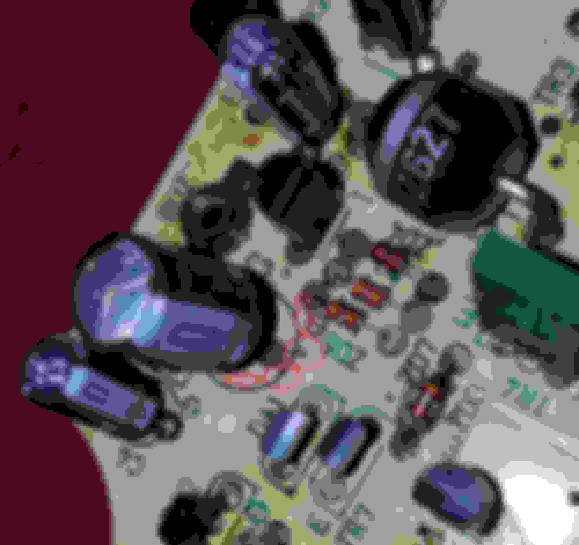
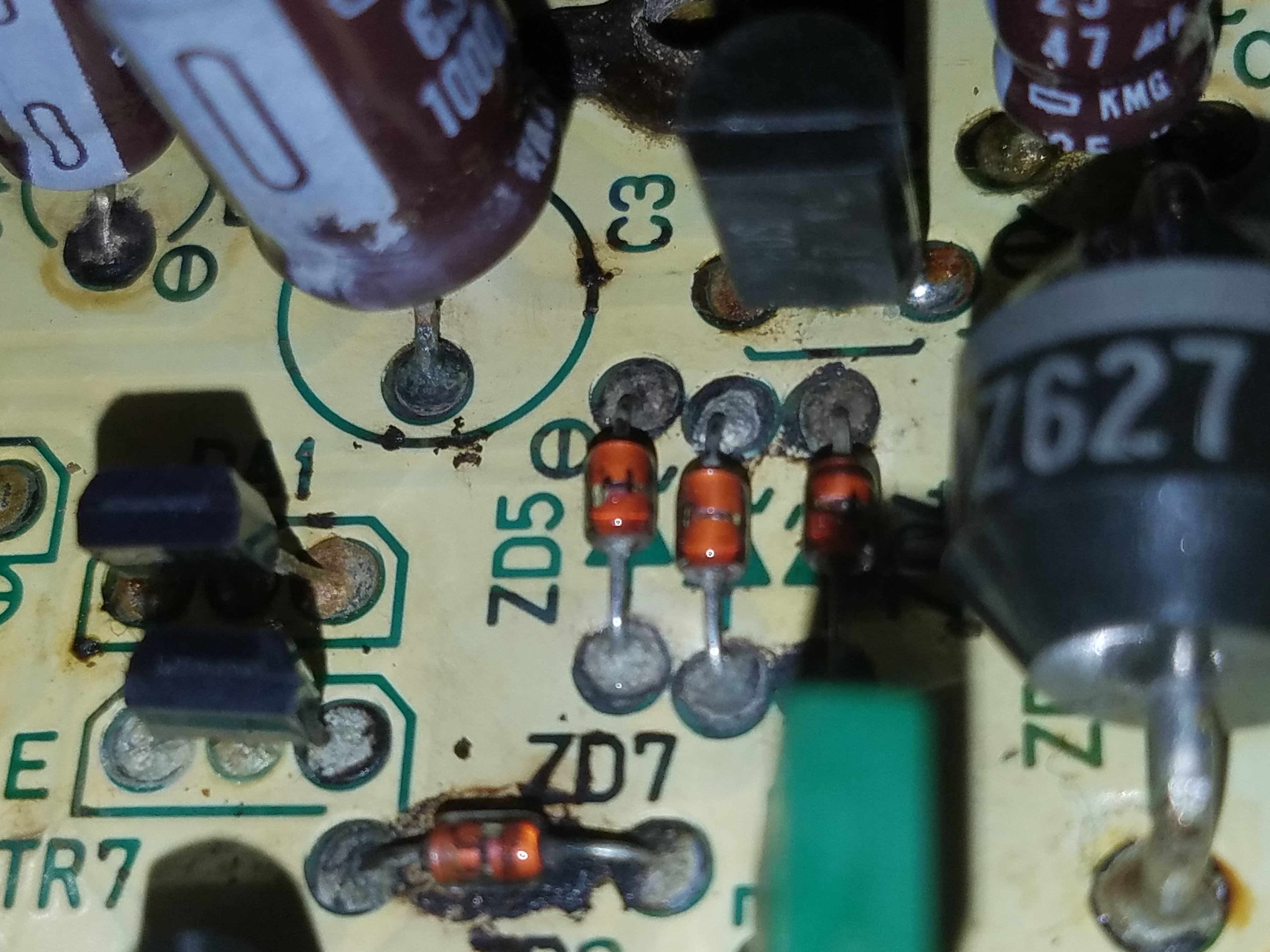
I cleaned up all the burnt marks and now nothing really looks bad to my eye. The component between ZD7 and ZD3 (not sure which is labeling it) still looks like it got hot or something. Unless C3 just leaked and it all flowed straight down. IDK
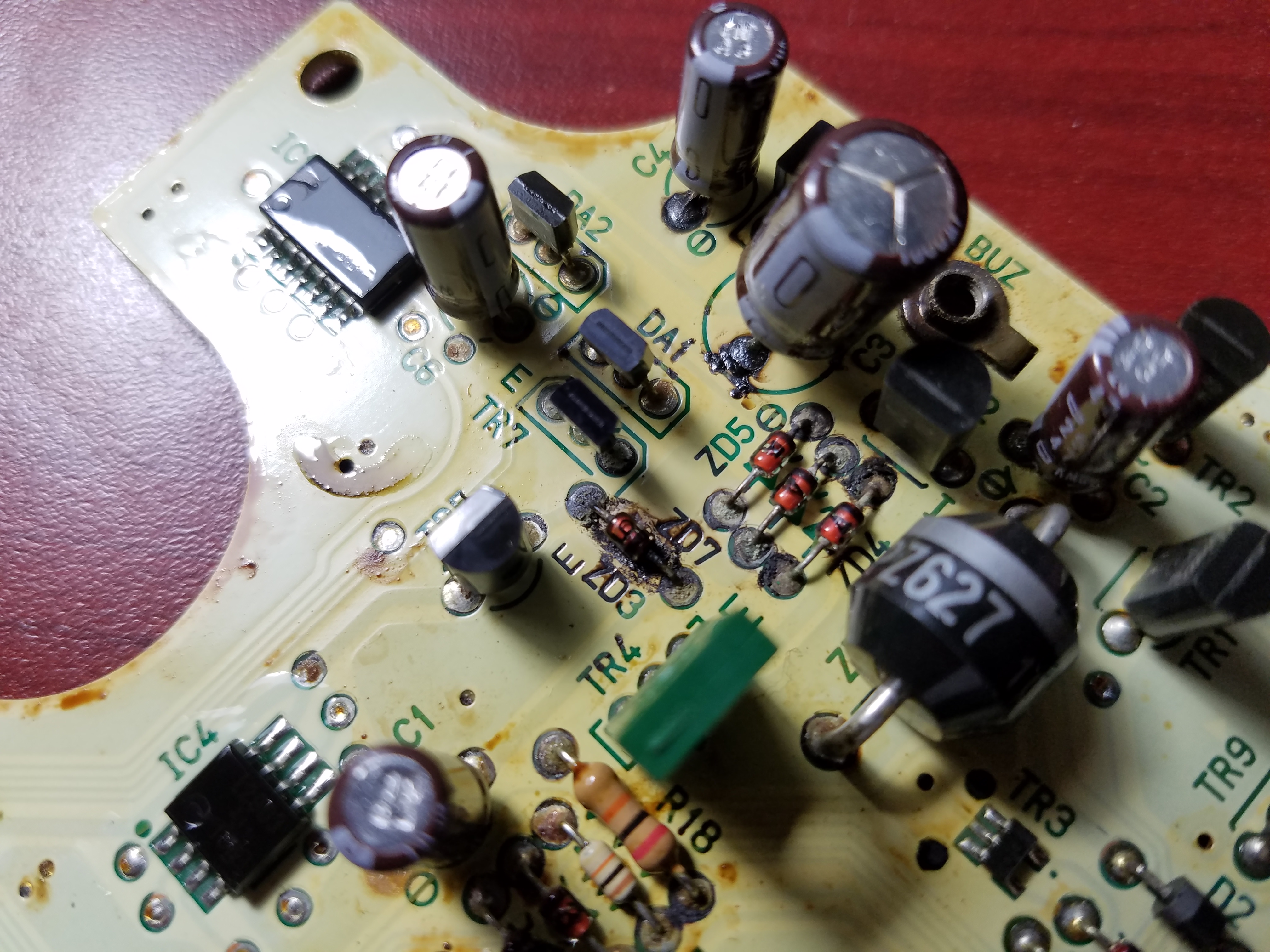
Here's some circles of what I'm seeing:
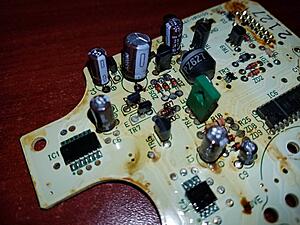
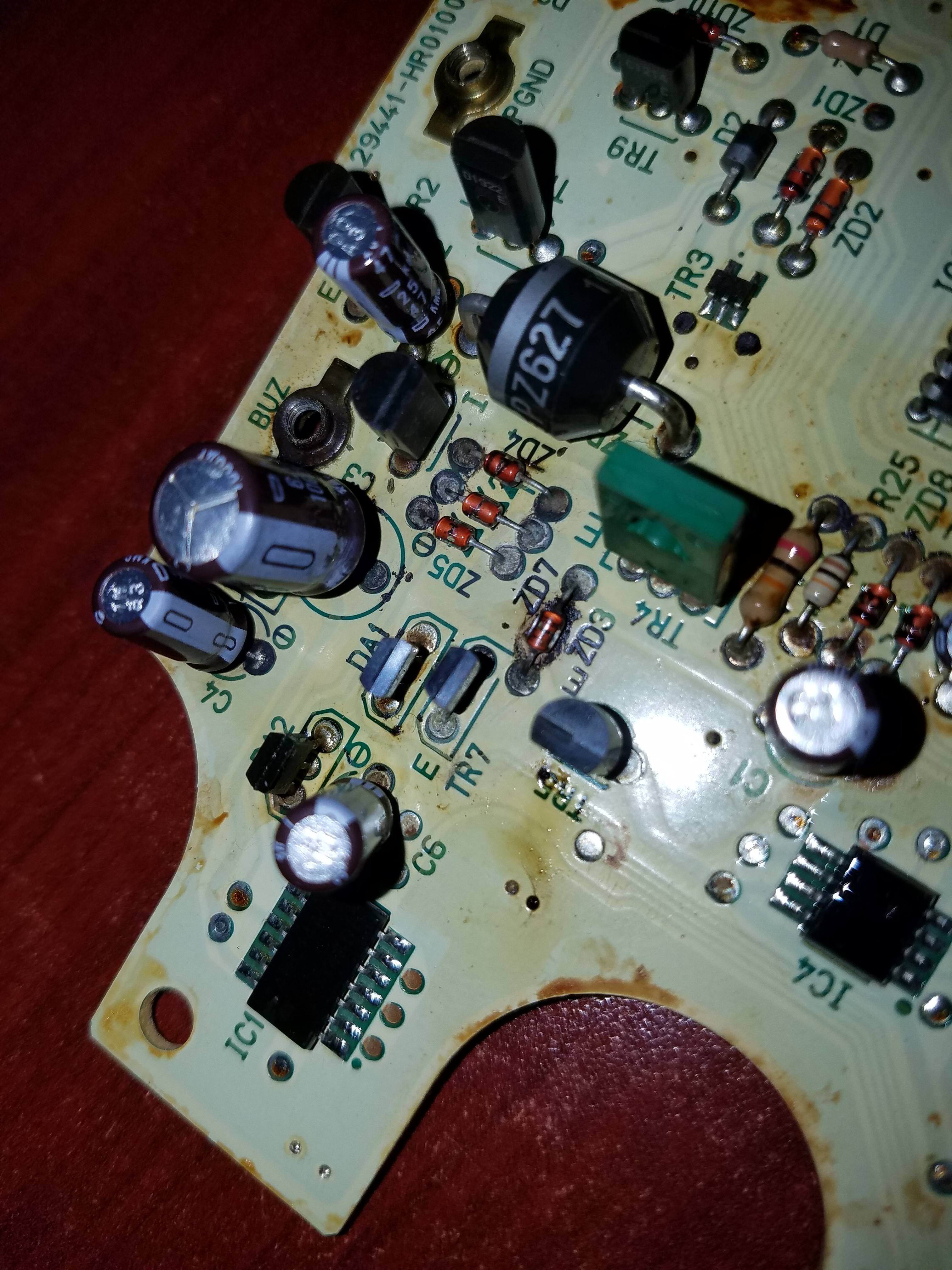
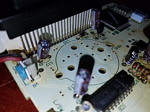
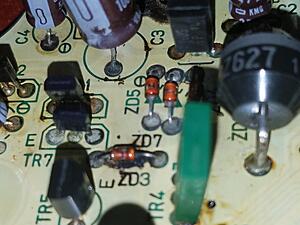
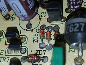
And here's a pic after a quick once over with a q-tip:
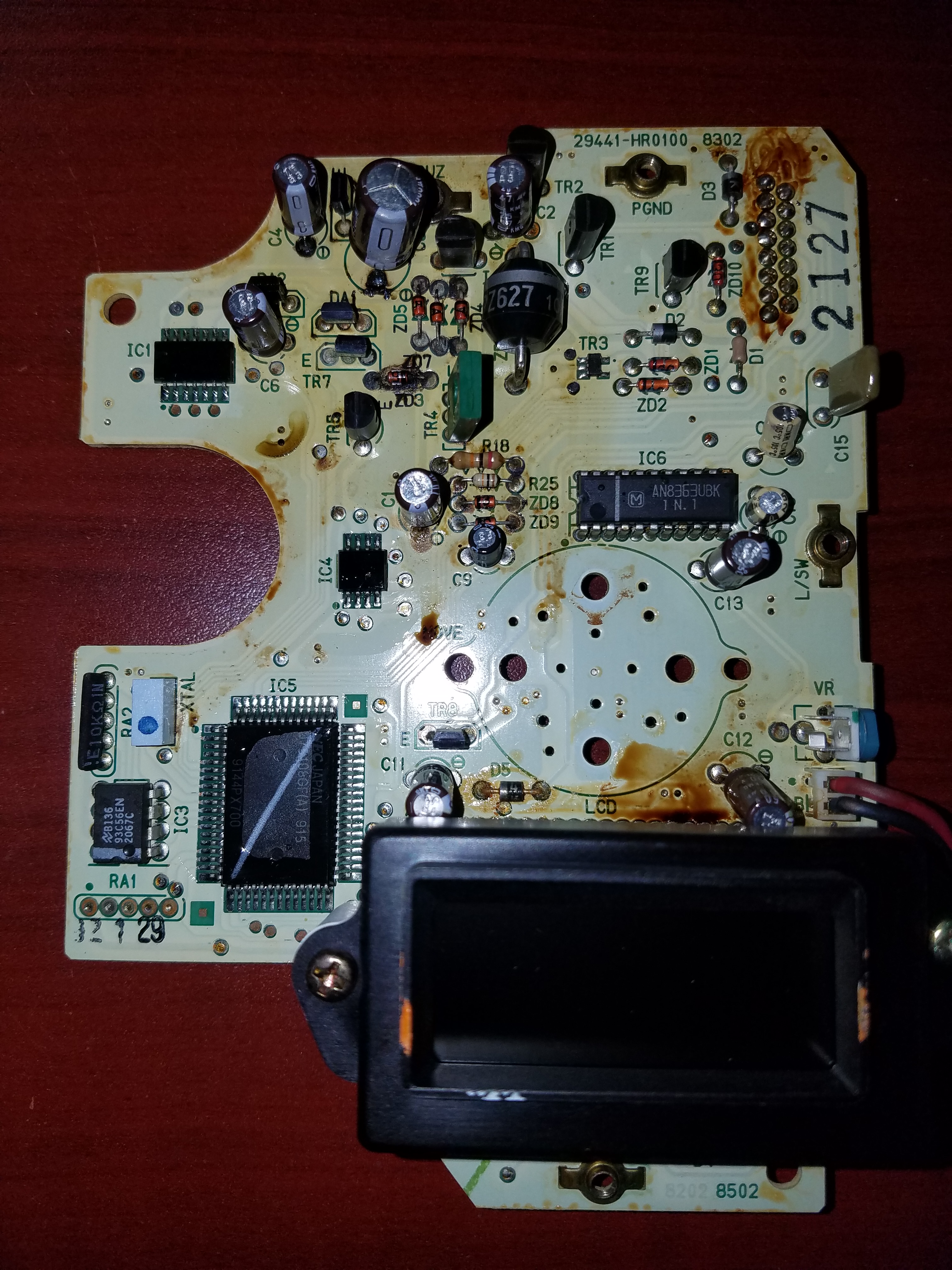
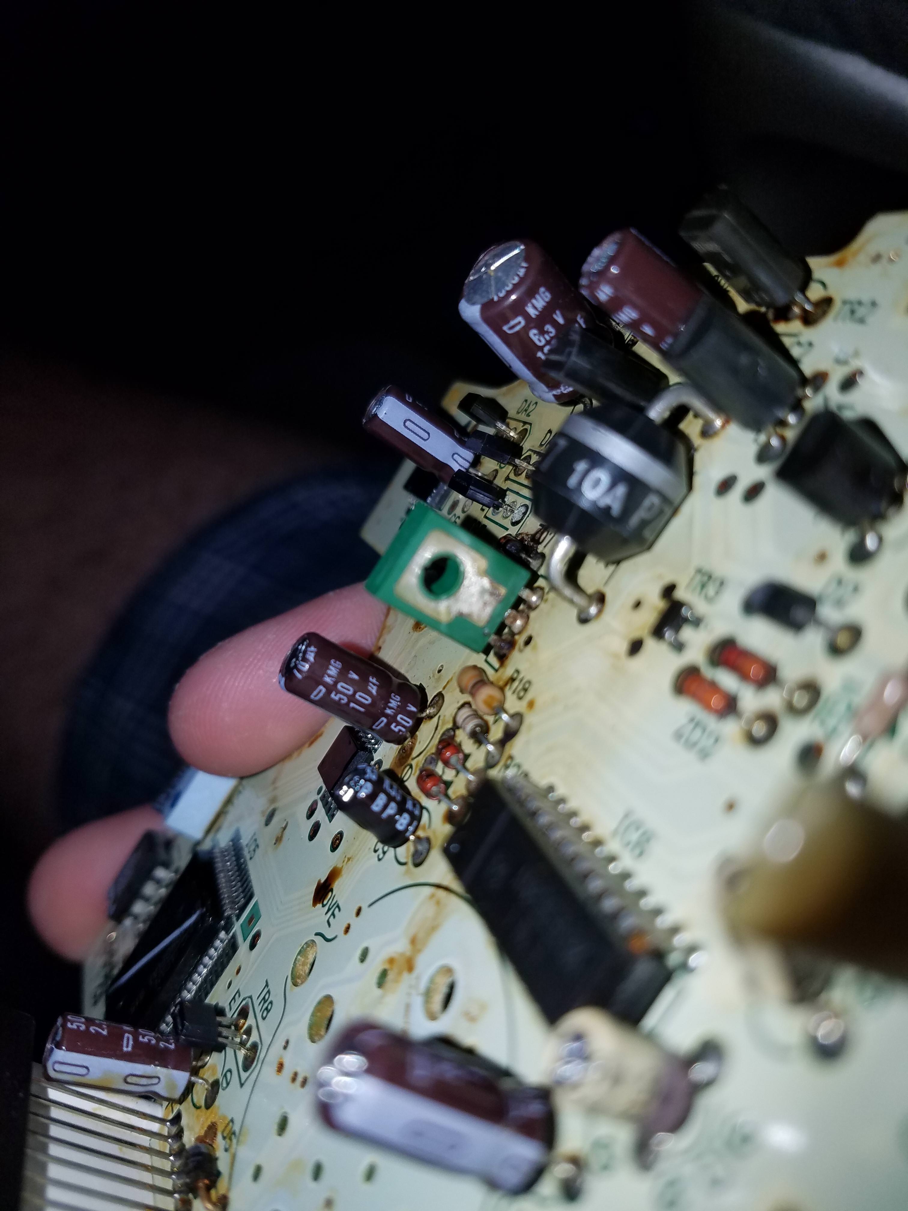
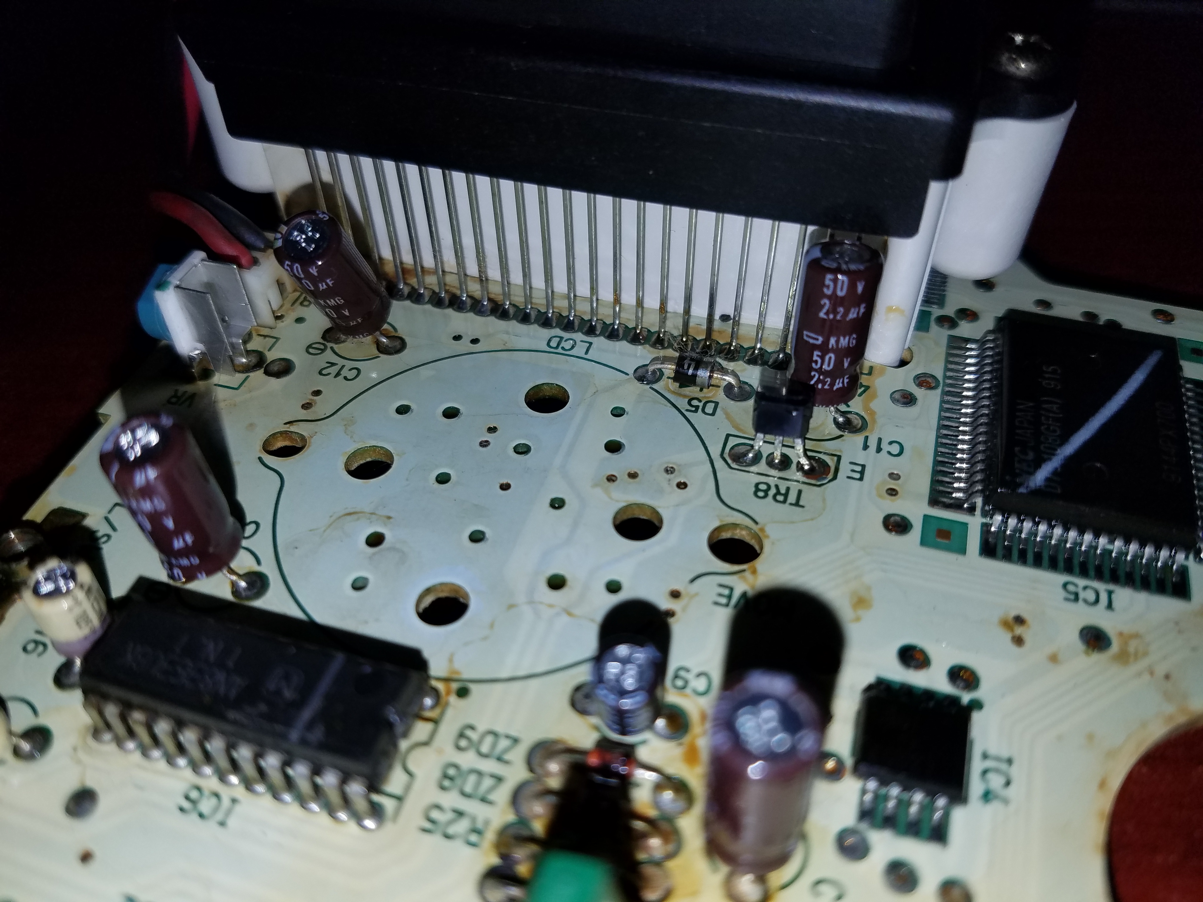
Thanks again for the 2nd set of photos. They helped a lot! You are correct in guessing the electrolyte leaked from C3 and it ran down the length of the board. Based upon the photos you posted, I would recommend replacing C1, C2, C3, & C4. Other capacitors may also need to be replaced. Could you take several more photos of the component side of the board around all the remaining capacitors? Please take some pics of the LCD Display top row of solder joints. Hit that with a q-tip & alcohol (if not already) too. I want to verify that those solder joints are okay. That is also in the vicinity of C12.
The Zener diodes (ZD4, ZD7, ZD5, & ZD3), Diode Array (DA1), and Power Transistor (TR7) should have their solder joints replaced. It looks like the acid (electrolyte) ate up those solder joints. The same procedure should also be done (replace solder) around R18 and surrounding components. BTW, ZD7 is in between ZD4 and ZD5. ZD3 is below that trio. I don't think it's necessary to replace these diodes yet since their part numbers are unknown, except for ZD4 and their solder joints only exhibit corrosion.
Could you also take some good photos of the back side of the board? I'm sure it's fine but I want to make certain that no damage exists there. Please refresh my memory: besides from the weird tach beeping and blank odo, does the speedo function normally?
As far as my issues go; you had both of them remembred correctly. Tach/something beeping all the time (which seemed to be caused by RPM rising/falling), and blank ODO. The speedo was functioning just fine. I actually put about 5 miles on the car before ripping the cluster out (and breaking the gauge hood) and it seemed to read speed just fine. I didn't get over ~70mph but it read up to that point fine. Didn't jump around or do anything odd.
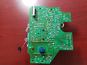
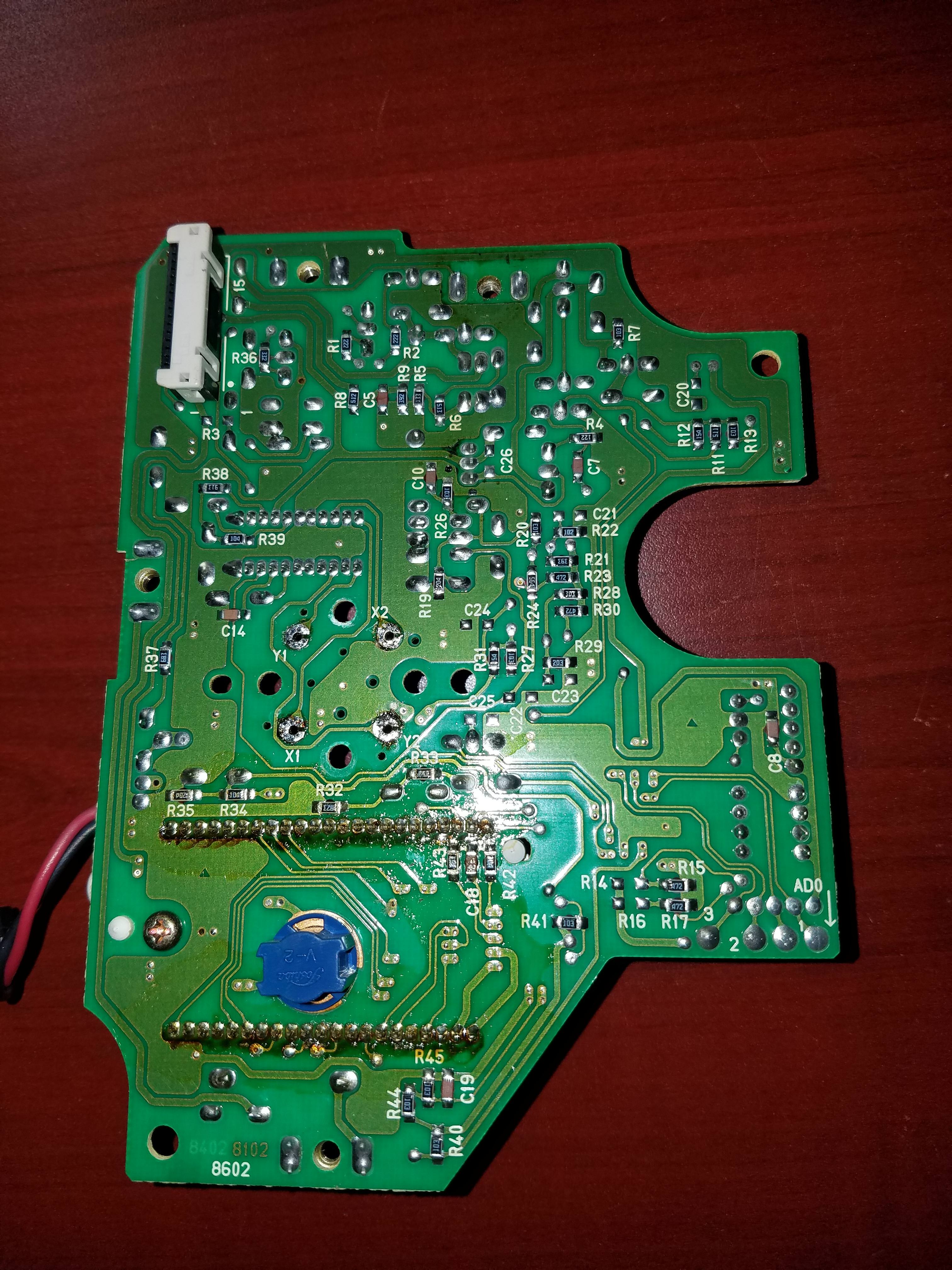
Here's the pics I took yesterday of the back side of the board. If you need to see more please let me know:
When I get home tonight I'll go over the whole board with alcohol and get the pictures you mentioned. By 'solder joints replaced' do you just mean heating the joint up, sucking the old solder out, and getting fresh solder in there? And you think ZD3 is ok? It was the worst looking component on the board IMO. I don't know what a diode is or does however so that statement is made with ignorance in mind.
Thanks so much, saving me upwards of a million dollars here as I think the only other option I'd consider is replacing all the gauges in the cluster with a dash pack or Speedhut gauges
I'm glad to help out. Yes, replacing solder joints means that the old solder is removed (sucked out) and fresh solder is installed. I suspect that ZD3 is ok, however it can be checked with a DMM to remove all doubt. Basically, a diode (Zener included) acts like a high-speed switch or check valve. It allows or prevents the current in a circuit to flow in one direction. Another analogy for a diode is the "One Way" road sign, although the sign doesn't prevent a car from going down the wrong way. Traffic will dictate that!
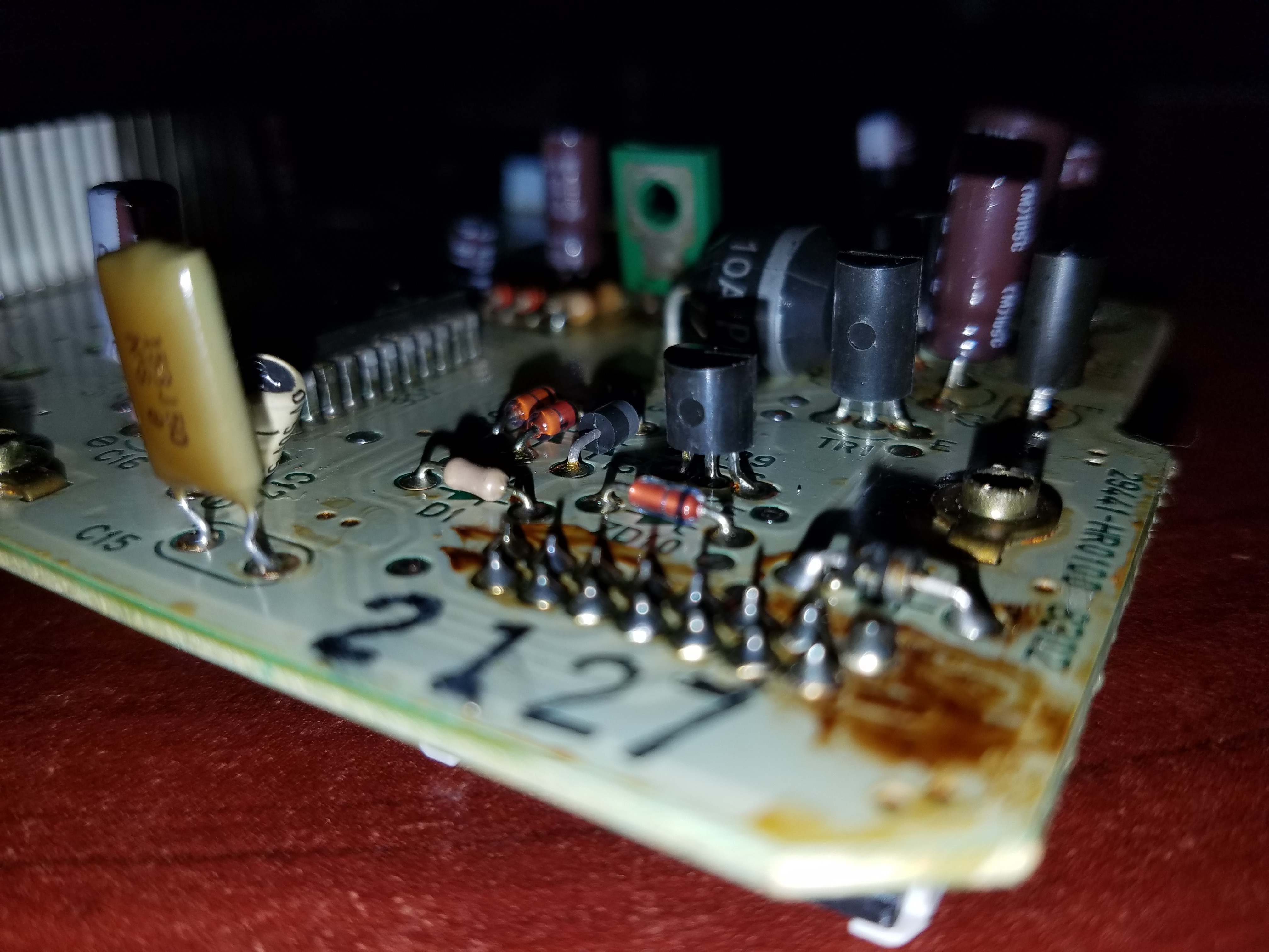
I don't see anything obvious on the back side of the board. It does look like someone once before removed the speedo faceplate. There are small char marks under the 4 solder joints from the 1st photo. You can easily see the crispy pads around the same eyelets in the 2nd photo. That is a sign that too much heat sat on each eyelet for a prolonged time. With enough soldering and de-soldering, the chance to lift an eyelet on any of those 4 increases. Trust me, you don't want a lifted eyelet!
One other recommendation on the back side of the board: remove the old solder flux (brown stuff) from the LCD Display solder joints with ye old trusty q-tip & alcohol.
The next big question to ask is do you plan on fixing this yourself or do you have someone local to lend a hand in soldering?
Thank you for attaching the remaining photos of your speedo board. Soldering components on a circuit board is a little more involved than soldering wires together. The concept remains the same. Please refer to my general soldering tips & tricks thread for some advice.
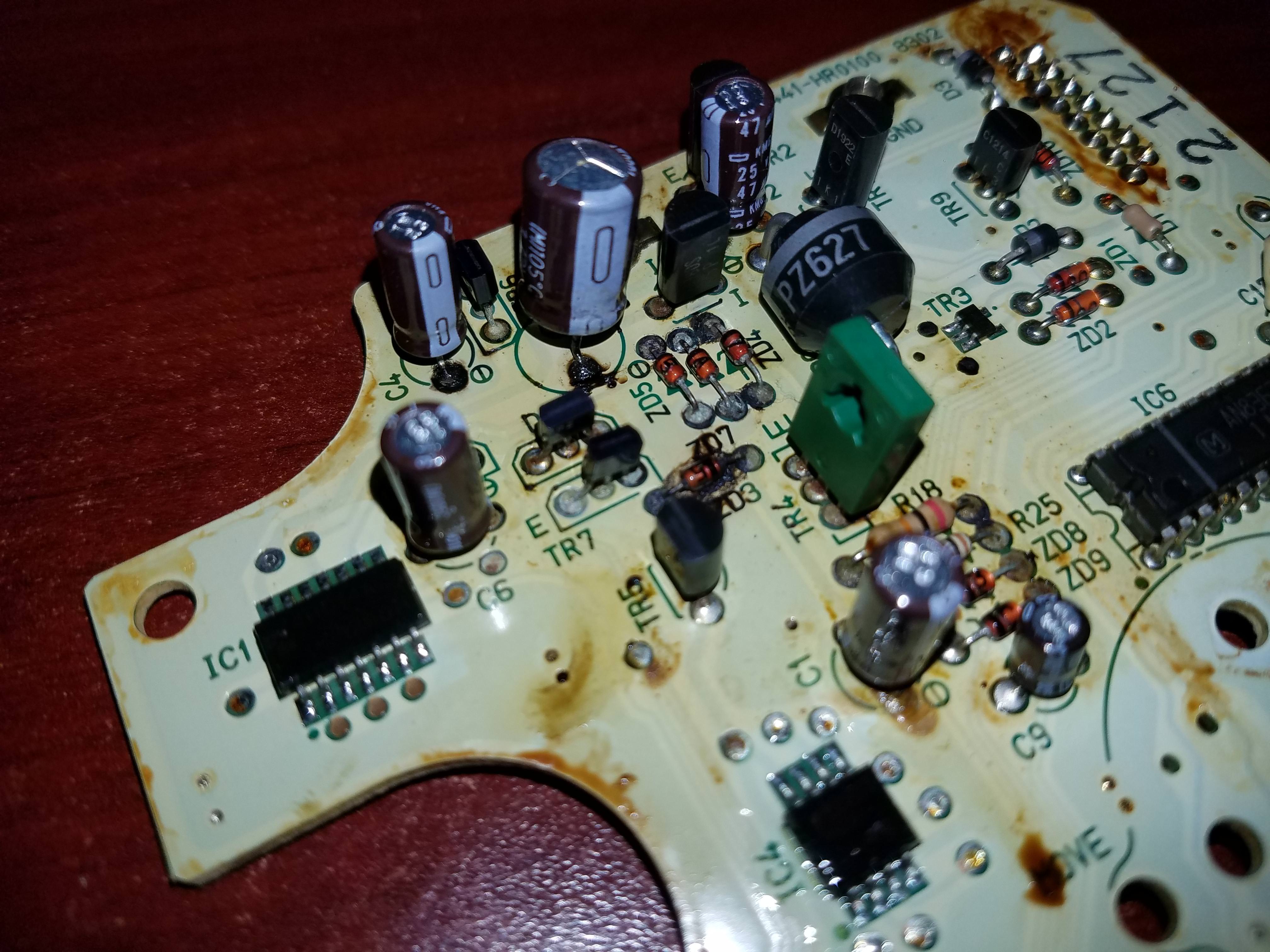
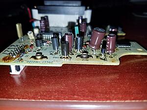
Back to the photos, I noticed something that you should see & comment on. It is barely visible in some instances because of shading from the flash. Some of the capacitors have slightly bulged tops. This indicates an internal failure because the electrolyte swelled from heat/age/power cycling. Specifically, look at C3, which already is bad, & C9. The top disc should be flat but these two look slightly bulged up.
Earlier I recommended replacing C1-C4 capacitors. I would like to amend that recommendation to include all the available electrolytic capacitors C1-C4, C6, and C9-C13. Think of these cap replacements as "refreshing your cell phone battery." You would also benefit from brand new electrolytic caps that would not leak for the rest of your ownership. This is more of a preventative maintenance step. Refer to this post: https://www.rx7club.com/3rd-generati.../#post12165092 that documents their replacement & part numbers (all of which ordered through DigiKey). Those part numbers are also listed on the earlier parts thread. Please be aware that the C9 replacement part number is not verified as a suitable replacement for the original. If C9's lid is not bulged (as indicated in the photo) then I would recommend replacing that capacitor last. Last replacement to mean replace the others, test the board, then replace C9 when the board is still giving you problems.
There is also another procedure that I'd like you to check. This pertains to the circuit board itself. Place a flashlight underneath the board and look for possible breaks in the solder runs (traces). EpyonFD did this and found a few problems. Examples of his photos are found here: https://www.rx7club.com/3rd-generati.../#post12217990
I see what you are saying about the picture(s) of C9 but in real life it appears to be fine. The only one I can see that is bulged upwards is in fact C3. I ordered every part number that digikey had from that thread and everything but 2 pieces they had in stock (they did not have C6 and C13 currently, eta is 3/8 or something).
I put a flashlight under the board and I believe I found one break:
I fear I may have just crossed over into the "no way am i fixing that" zone lol. It looks like Epyon had a break in the same spot as well. Is the fix for that to solder a piece of wire on the front/back of the board to bypass the break?
It's Mouser P/N: 647-UEP1H010MDD, Mfr P/N: UEP1H010MDD. It's made by Nichion and is presently in stock!
Now let's address that break in the solder trace! First, I am glad that you quickly found something. It's better to find this potential problem now vice chasing a ghost later. Second, there is a way to verify that the trace is either good or bad! Do you have a DMM? Check for resistance, not continuity, of this trace. It starts at the top end (negative side) of ZD5. You will need to follow that trace to another solder point with the flashlight. Connect the Negative (Black) Lead of the DMM on ZD5's solder joint. I would recommend a light scuff of that joint with the probe's tip to reveal a bit of fresh solder. Do not gouge it. Then connect the Positive (Red) Lead of the DMM to the opposite end of that solder trace. The meter should read 0 (ZERO) Ohms, which means the trace is a short. That is a good reading. If it reads "OL" then the meter indicates an open circuit (infinite ohms); which is a bad reading. Alternately, if the meter measures a value other than 0 or OL, then swap each lead's position and re-measure. If that same resistance value is observed then the trace is good. Swapping the leads may eliminate alternate paths to the meter. Finally, make sure you touch the leads together to verify the meter reads 0 ohms before you take a measurement. This step verifies the meter is working normally.
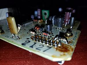
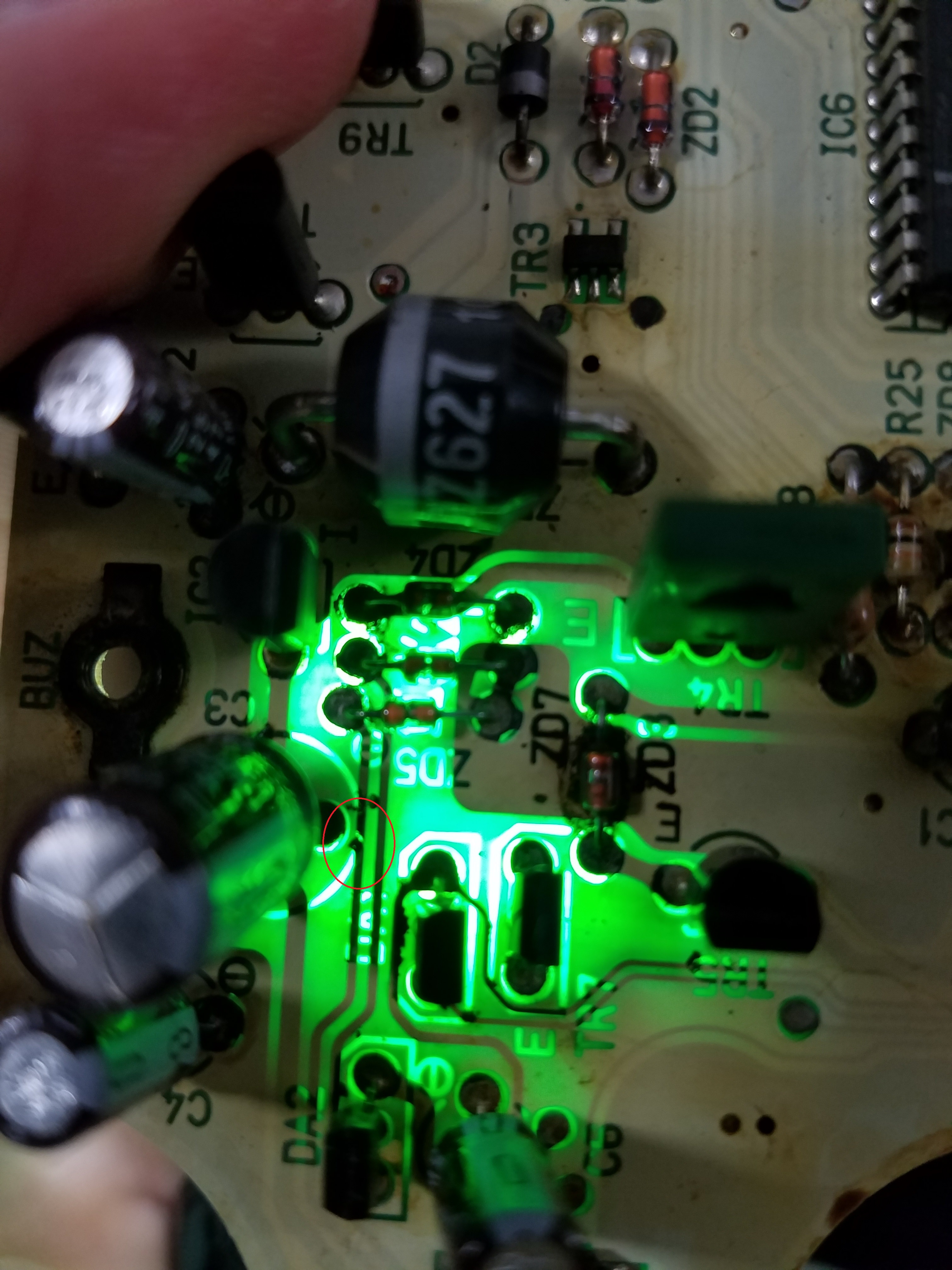
Lastly, I revisited one of your photos. Take a look at this area on the board.
It does look like the trace broke through the surface of the board. Run a tooth pick over it. Does it feel smooth or broken? If you feel a break then do NOT pick at it. Try to take a photo of it with Zoom-in function, with flash on, and with flash off at varying angles to visually spot the break. Did the rest of the board look ok under the flashlight?
Hang in there, Bill. Don't give up the ship!
Cheers,
George
That spot you have circled is the spot I took a picture of with the flashlight under the board. Am I missing something? I only see the one break there with the flashlight. I poked that black spot as well with a toothpick and it is raised.
Yes I have a DMM, I'm already in for the night but tomorrow I'll bring it inside and start poking around like you instructed.
Also my DigiKey order already shipped! Tracking says the stuff will be here Tuesday.
The "broken" trace in the flashlight pic actually comes into contact with the painted circle for C3. Maybe the circular paint caused an optical illusion? The one solder trace closest to ZD5 looks like it runs to ZD7; it looks lower than the trace that connects to ZD5. The lower trace goes to the top of ZD7 when compared the normal pic to the flashlight pic. When you have the time tomorrow, please check out both traces given the method I described above. Resist the urge to push that one raised spot down during your resistance checks. Just check them both as-is.
Good to hear about the DigiKey order. They are typically fast! Did you order the other 2 caps from Mouser?
Cheers,
George
Last edited by Gen2n3; Dec 21, 2017 at 08:32 PM.
Reason: Added DigiKey remarks.
I'll get those other 2 caps ordered up tomorrow morning for sure, thanks for tracking them down.
Tomorrow I'll get the meter in here and let you know what I find. I was able to get two zoomed in pics of the junk under C3. I can't really tell what happened there. Hopefully the DMM will tell the story better.
I have good news and more good news. First, the good news about checking both traces. Well done! On to more good news, the ZD5 trace sounds good, even with a measurement of 4.1M Ohm. If the trace
was broken then it would read OL (infinite ohms).
The 4.1M ohm must be reading through other components connected to that trace.
After researching suitable replacements for TR5 (2SC458), I cross-referenced its specs on Mouser and found this: BC548 series transistor, made by ON Semiconductors. The differences between the original and this substitute are the larger power dissipation of 500mW as opposed to the original 200mW, and a higher Gain Bandwidth of 300MHz as opposed to the original 230MHz. The original also has a Transition Frequency (Ft) of 115MHz however, I did not see that specification on the substitute. Other differences include an increase in Collector Capacitance of 6pF (original has 4pF), and a Forward Current Transfer Ratio (Hfe) of 110 (original has a min of 60).
Despite these differences, I believe that the BC548 series is an acceptable replacement. Its data sheet is attached below for further review/discussion. Specifically, the proper replacement transistor from Mouser is 512-BC549BTF (Mouser P/N), BC549BTF (Manufacturer P/N).
I must amend my initial research about TR5 from the above post because of newly discovered evidence. Please read this cross-referenced link for the details: Suitable TR5 Replacement
In short, the BC548 transistor is electrically similar to the original specification of the 2SC458 transistor. The major difference between them are the arrangement of the Emitter, Base, and Collector legs. The proper leg arrangement for the 2SC458 transistor is Emitter, Collector, Base. If this orientation is not followed with a replacement transistor then the circuit may still not function properly.
The only equivalent transistor and leg orientation to the original 2SC458 transistor is KSC1845. Audiophiles use this specific transistor as a direct replacement for the 2SC458 transistor and they even argue it generates considerably less noise than the original (2SC458).
This new information is based upon physical differences and spec sheets between BC458, KSC1845, and 2SC458 transistors.
In summary, I now suggest that KSC1845 could be a better replacement. This academic approach will need to be verified! Therefore, please comment or provide feedback if Members wish to proceed with a replacement for TR5.
Hope I am in the right thread
Originally odometer was not working => replaced all diodes / capacitors and now works YET Speedo at idle has decided to show some MPH !!! (ie. car is not moving yet Speedo is showing speed) - once car moves Speedo works fine until car stops again. Then sometimes after a few miles everything works fine.
Any ideas more than welcome !
For members who only read this thread, Groovin's original question was posted here: Post #301
And he asked:
"Can anyone provide some input on my tach? The tach personality seems to vary. With bumps or sometimes just randomly it'll jump and spike over 9k rpm. It can sit there or jump back down. Sometimes it chooses not to work at all while other timesr times it'll bounces around. Lastly there are moments when it reads really low as if its counting only have the RPM and doesn't go above 2-3k rpm when clearly the car is reving. I tried jumping the ground, seemed to smooth things out a bit but notice it jumped to 9k for a moment and returned. Decided to jump a 12v at the same time. Seems more accurate with the cold and even just a bit smoother but yet again I saw it spike to 9k but instantly returned. Any thoughts on the chaotic "over 9000!" rpm spike? Thanks in advance."
Groovin,
First, please remove the speedo board and inspect it for damaged components. Take photos of it and post it here. You may need to desolder the speedo face from the board. Are you able to do that? Refer to my general soldering thread for advice & necessary tools if you have not done that before. Soldering components on a circuit board is a bit more involved than soldering 2 wires together.
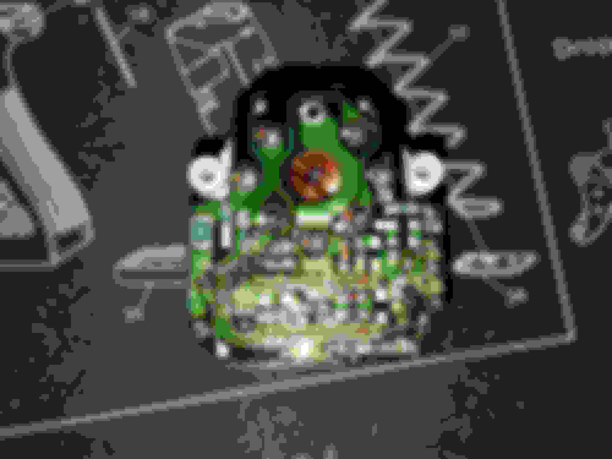
I have a few comments about the photos you posted. My comments on them will be in the photo's caption.
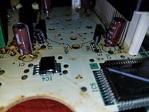
What are these dark spots inside the connector sockets? They are in the red circled areas.
Different angle of the dark spot. Could that socket have damaged walls? If the wall is damaged then the flex print may not seat well against the hard plastic connector.
I suspect this capacitor, C1, was previously replaced. What are the values stamped on the capacitor? It should be 1uF @ 50V.
The capacitor for C5 may not be the proper one. The code stamped on it looks like a 0.01uF @ 100V. It should be a 0.015uF @ 50V. The solder joints do not look good either. The poor solder joint could also be part of the problem.
Please clean up the back side of this board with isopropyl alcohol, a tooth brush and/or cotton swab. The brown stains are years of dried flux and should clean up well. Then take another photo of it & post, please. Excessive solder appears to exist on the joint of R11, a SMD component (not highlighted).
Nice Glock cleaning mat, btw!
For component locations, values, and part numbers on the tachometer board, refer to my other thread: FD Tach Components
Besides the potential damage to the connector sockets on the instrument cluster, I do not see anything unusual. How does the flex print that connects to the speedo board look?
Cheers,
George
Last edited by Gen2n3; Mar 18, 2018 at 09:45 PM.
Reason: Added preface.
Unfortunately mine stopped working again, and the beeping is back
I unplugged CPU2 for the time being so I can drive the car without being beeped at constantly :P
Bill,
I'm sorry to hear that your problem returned. Please remove the speedo board and inspect it for other potential problems. Use the methods we previously discussed.