When you click on links to various merchants on this site and make a purchase, this can result in this site earning a commission. Affiliate programs and affiliations include, but are not limited to, the eBay Partner Network.
@Gen2n3 asked me if i could check up some of the EU diagrams. Here are the ones for cluster and CPU 1 and 2:
Really Thanks @Zepticon Thanks to Your diagrams I found a possible problem on my CPU2 since the pin 1G from CPU2 is giving out V4,85 instead of Battery voltage and is taking V12,40 from 1E ignition switch
To be sure I saw the color was the same reported on You picture and i checked also continuity between pin 1G of cpu2 and pin 3B of instrument cluster C1-01 3series (which also measure V 4,85)
So now i have to search for problem or fix CPU2 which was looking in very good condition.
Thanks also to @Gen2n3 for asking Zepticon manuals, without You i couldn't have this picture.
Dear George,
thanks for Your time.
According to flow chart 23 / flow chart 24 and the table voltage of CPU2 i should have battery voltage at pin 1G I have only 4,85V or less.
Don't You think this is abnormal?
@Zepticon sorry if I bore You, may You please share the flow chart 23/24 on the USA manual is page C2-34 C2-35 C2-36 under Warning system of the body electrical manual
Nearly all of the steps are identical with the exception of Steps 1 and 2. Here are the steps you should follow using Zepticon's schematic and cross-referencing the Flowchart #23 - Coolant level warning alarm does not sound when coolant fluid low level (coolant level warning light illuminates):
Step 1:
1. Turn the ignition switch to ON.
2. Measure the voltage at terminal E (Pin 1E) (B/Y) of the CPU #2 connector (17-pin).
Result:
B+ voltage = Go to Step 2
Others = Repair wiring harness (METER 15A fuse-CPU No 2)
Editor note: This step verifies 12v batter power flows to the circuit.
Step 2:
Measure the voltage at terminal G (Pin 1G) (BR) of the CPU #2 connector (17-pin).
Result:
B+ voltage = Go to Step 3
Others = Relpace CPU No 2 (Refer to section Z3)
Editor note: This step verifies the Buzzer signal coming from the speedometer circuit board is sent to the Body CPU.
Step 3:
1. Turn the ignition switch to OFF.
2. Remove the instrument cluster. (Refer to section C1).
3. Turn the ignition switch to ON.
4. Measure the voltage at terminal 3B (BR) of the instrument cluster connector C1-01-3 (12-pin).
Result:
B+ voltage = Go to Step 4.
Other = Repair wiring harness (CPU No 2-Instrument cluster)
Editor Note: This step verifies the Buzzer signal output from the speedometer circuit board.
Step 4:
1. Disconnect the coolant level sensor connector, C-07.
2. Check for continuity between the terminal of the coolant level sensor and ground.
Result:
Engine Coolant level Below MIN = No continuity (Open circuit)
Engine Coolant level Above MIN = Continuity (Short circuit)
3. If correct, connect the coolant level sensor connector and go to Step 5.
4. If not as specified, replace the coolant level sensor. (Refer to Page C2-37).
Editor note: This step verifies the condition of the coolant level sensor.
Step 5:
1. Check for continuity between terminal 3D (BR/W) of instrument cluster connector C1-01-3 (12-pin) and ground.
Result:
Engine Coolant level Below MIN = No continuity (Open circuit)
Engine Coolant level Above MIN = Continuity (Short circuit)
2. If correct, replace the instrument cluster. (Refer to section C1.)
3. If not as specified, repair the wiring harness (instrument cluster-coolant level sensor).
Editor note: This step verifies the coolant level sensor signal is sent to the speedometer circuit board.
Last edited by Gen2n3; Apr 26, 2020 at 11:10 PM.
Reason: Added title to Flowchart 23
Here are the modifications to follow for Flowchart #24 - Over-revolution warning alarm does not sound when tachometer indicates red zone:
Step 1:
1. Turn the ignition switch to ON.
2. Measure the voltage at terminal E (Pin 1E) (B/Y) of the CPU #2 connector (17-pin).
Result:
B+ voltage = Go to Step 2
Others = Repair wiring harness (METER 15A fuse-CPU No 2)
Editor note: This step verifies 12v batter power flows to the circuit.
Step 2:
Measure the voltage at terminal G (Pin 1G) (BR) of the CPU #2 connector (17-pin).
Result:
B+ voltage = Go to Step 3
Others = Relpace CPU No 2 (Refer to section Z3)
Editor note: This step verifies the Buzzer signal coming from the speedometer circuit board is sent to the Body CPU.
Step 3:
1. Turn the ignition switch to OFF.
2. Remove the instrument cluster. (Refer to section C1).
3. Turn the ignition switch to ON.
4. Measure the voltage at terminal 3B (BR) of the instrument cluster connector C1-01-3 (12-pin).
Result:
B+ voltage = Go to Step 4.
Other = Repair wiring harness (CPU No 2-Instrument cluster)
Editor Note: This step verifies the Buzzer signal output from the speedometer circuit board.
Step 4:
1. Measure the voltage at terminal 3F (Y/L) of the instrument cluster connector, C1-01-3 (12-pin).
Dear George,
thanks for Your time.
According to flow chart 23 / flow chart 24 and the table voltage of CPU2 i should have battery voltage at pin 1G I have only 4,85V or less.
Don't You think this is abnormal?
Pietro,
You are very welcome. You are correct, that is an abnormal indication. Since you have an unusual indication on Pin 1G, please check the following:
1. Disconnect the J3-01 (17-pin) connector.
2. Connect a wire from Connector J3-01, Pin G (1G) to chassis ground.
3, At the instrument cluster, disconnect Connector C1-01-3 (12-pin) connector.
4. Test for continuity (short) between Pin 3B and ground.
Result:
Continuity (short circuit) between 3B and ground = wire harness is good, go to Step 10.
No continuity (open circuit) between 3B and ground = Go to next step.
5. Disconnect Connector X-19.
6. Connect a wire from X-19 (BR) (Instrument wire harness side) to chassis ground.
7. Repeat continuity test between Pin 3B and chassis ground.
Result:
Continuity (short circuit) between 3B and ground = wire harness is good, go to next step.
No continuity (open circuit) between 3B and ground = repair wire harness.
8. Move ground wire from X-19 (BR) (Instrument wire harness side) to X-19 (BR) on the Dashboard wire harness side.
9. Test for continuity at J3-01 Pin G (1G) and ground.
Result:
Continuity (short circuit) between 1G and ground = wire harness is good.
No continuity (open circuit) between 1G and ground = repair wire harness.
10. If all wires pass continuity tests then remove wires to chassis ground.
11. Connect Connector J3-01 to Body CPU.
12. Replace speedometer circuit board; Remove and inspect speedometer circuit board for potential damage to components.
@Zepticon sorry if I bore You, may You please share the flow chart 23/24 on the USA manual is page C2-34 C2-35 C2-36 under Warning system of the body electrical manual
THe two pages i posted up is everything i got on warning systems and dash. Ca and Cb.
Zepticon,
I believe Pietro was asking if you have the body electrical troubleshooting manual and if you could share a photo of the flowcharts 23 & 24.
I think i have all the manual, but its hard to figure out what flowchart you mean as its in German and a different page number
If i get a picture of the relevant diagram i can find the EU version if i have it.
Also, i would love it if you have the US electrical diagrams in PDF. I only have the main book, not any of the smaller ones, and the Electrical would be a good addition to the collection.
Originally Posted by Gen2n3
I previously asked if you could share Diagram B-1b. If that isn't possible, could you please confirm what ECU pin is connected to the B/Y wire?
That wire sends the TAM signal to the speedometer board at C1-01 Pin 3F. That should be cross-ref #14.
Again, thank you for all of your help!
Does this help?
Last edited by Zepticon; Apr 27, 2020 at 02:43 AM.
Here are the modifications to follow for Flowchart #24 - Over-revolution warning alarm does not sound when tachometer indicates red zone:
Step 1:
1. Turn the ignition switch to ON.
2. Measure the voltage at terminal E (Pin 1E) (B/Y) of the CPU #2 connector (17-pin).
Result:
B+ voltage = Go to Step 2
Others = Repair wiring harness (METER 15A fuse-CPU No 2)
Editor note: This step verifies 12v batter power flows to the circuit.
Step 2:
Measure the voltage at terminal G (Pin 1G) (BR) of the CPU #2 connector (17-pin).
Result:
B+ voltage = Go to Step 3
Others = Relpace CPU No 2 (Refer to section Z3)
Editor note: This step verifies the Buzzer signal coming from the speedometer circuit board is sent to the Body CPU.
I have V4,85 so according to manuals I have a problem with CPU2?
Editor note: This step verifies the Buzzer signal coming from the speedometer circuit board is sent to the Body CPU
Question: The signal came from? or go to the cluster? With all cluster disconnected i still read V4,85 so i suppose is something that go to the cluster.
Originally Posted by Gen2n3
Pietro,
You are very welcome. You are correct, that is an abnormal indication. Since you have an unusual indication on Pin 1G, please check the following:
1. Disconnect the J3-01 (17-pin) connector.
2. Connect a wire from Connector J3-01, Pin G (1G) to chassis ground.
3, At the instrument cluster, disconnect Connector C1-01-3 (12-pin) connector.
4. Test for continuity (short) between Pin 3B and ground.
Result:
Continuity (short circuit) between 3B and ground = wire harness is good, go to Step 10.
10. If all wires pass continuity tests then remove wires to chassis ground.
11. Connect Connector J3-01 to Body CPU.
12. Replace speedometer circuit board; Remove and inspect speedometer circuit board for potential damage to components.
Also here same questions.
I made all the check as You so kindly wrote to me.
After point 4 i went direct to point 10 since the cable was good.
But if I have V4,85 instead of around 12 (battery voltage) why i should not suspect the CPU2 problem instead of a Cluster?
The only thinks that let me guess that the cluster is not working is that i have 2 cluster and with one is working with other not.
The question is concerning the value of the voltage if is normal or not. Even in the Zpeticon manual is wrote i should run battery voltage on CPU2 1G pin.
I made also a test with my working cluster i disconnected the coolant sensor and the buzzer started to beep. So i guess You right the cluster is to replace.
Thanks for reply and so much for help.
Pietro
Last edited by pietrino; Apr 27, 2020 at 08:47 AM.
Reason: Added last test made
Pin 1G is +12V input signal to the Body CPU. That signal is generated by the Speedometer circuit board and is an output at Pin 3B. I figured that the entire length of wire from the instrument cluster to the Body CPU was good because you can hear the buzzer alarm. I asked you to check the continuity of the brown wire to be certain everything was tested.
Did you use a different speedometer when you used the other instrument cluster?
I suggest that you remove and label both speedometers. Take some photos of the components and I could offer some advise to their condition. You do not have to remove the speedometer face from the rest of the circuit board unless I notice something unusual or something is hidden.
I suggest that you remove and label both speedometers. Take some photos of the components and I could offer some advise to their condition. You do not have to remove the speedometer face from the rest of the circuit board unless I notice something unusual or something is hidden.
Dear George,
Thanks for offering me Your help and time.
The new speedometer not working was looking very new, not even a little oxidation in any part of the circuit board (from above, from each side, checked component by component all pin etc etc) looked with the magnifier glass. So today I shipped back to the seller.
I will start to fix my speedometer which has some leak from condenser and some diodes burned. I hope tomorrow to disassemble it and start to prepare a list of component to buy.
I saw that You made a fantastic thread on how to fix it with the list of each component. It will be very helpful.
I will keep You updated
Pietro
Did you send the new speedometer back or the entire instrument cluster? Either way, I'm sorry that you had to send it back. Did you reclaim IC3 from the new speedometer before returning it? As I remember, you installed your old IC3 to retain the odometer reading.
Yes, my Speedometer Parts thread is available for use. It will help you fix the speedometer with the right parts. However, the diodes on the speedometer are hard to find replacements. Are you sure your diodes are damaged?
Sometimes, leaked electrolyte from a capacitor will look like burn marks on surrounding components. For example, Post #26 of this thread shows damage to several components. These appear to be burned. However, it cleaned up with isopropyl alcohol. That damage was actually leaked electrolyte from capacitors C3 and C6! You can see that it cleaned up in Posts 36 & 37 of that same thread. When you have the time, take photos of the damaged board and post them. I'll be happy to offer advice when needed.
You may have a hard time identifying bad capacitors on the circuit board. There is a special tool that can help identify a bad capacitor. It is called an LCR meter. An LCR meter stands for Inductance-Capacitance-Resistance meter. It is specifically designed to measure the inductance of a coil (inductor), the capacitance of a capacitor, and the resistance of a resistor. Search Amazon for this device: Proster LCR Meter LCR Multimeter Tester for Capacitance Resistance Inductance Measuring Meter with LCD Over-range Display. I used this unit a few times on the speedo board to reveal capacitance values on the surface mounted device (SMD) capacitors.
Replacing the electrolytic capacitors on the speedo board will usually bring it back to life.
Dear George,
Yes I swapped again the IC3 chip and I also restored the R15 resistor.
About Zender diods i changed one already 1 year ago (see on pics ZD3 is broken)
It worked a little bit now is working now and then.
So i will open and change at least all capacitor and TR7, once i will open again i will send You a better Pics.
Thank You very much for helping me my speedometer 1 year ag�
Those diodes and transistor are not burned. That is leaked acid from the capacitors. Clean up the area around C4, C6, C2, C3, and C1 with isopropyl alcohol, a cotton swab and a tooth brush. Afterwards, inspect the legs of the affected components. You can post pictures of what you find.
You may be surprised to see that burned stuff will come off.
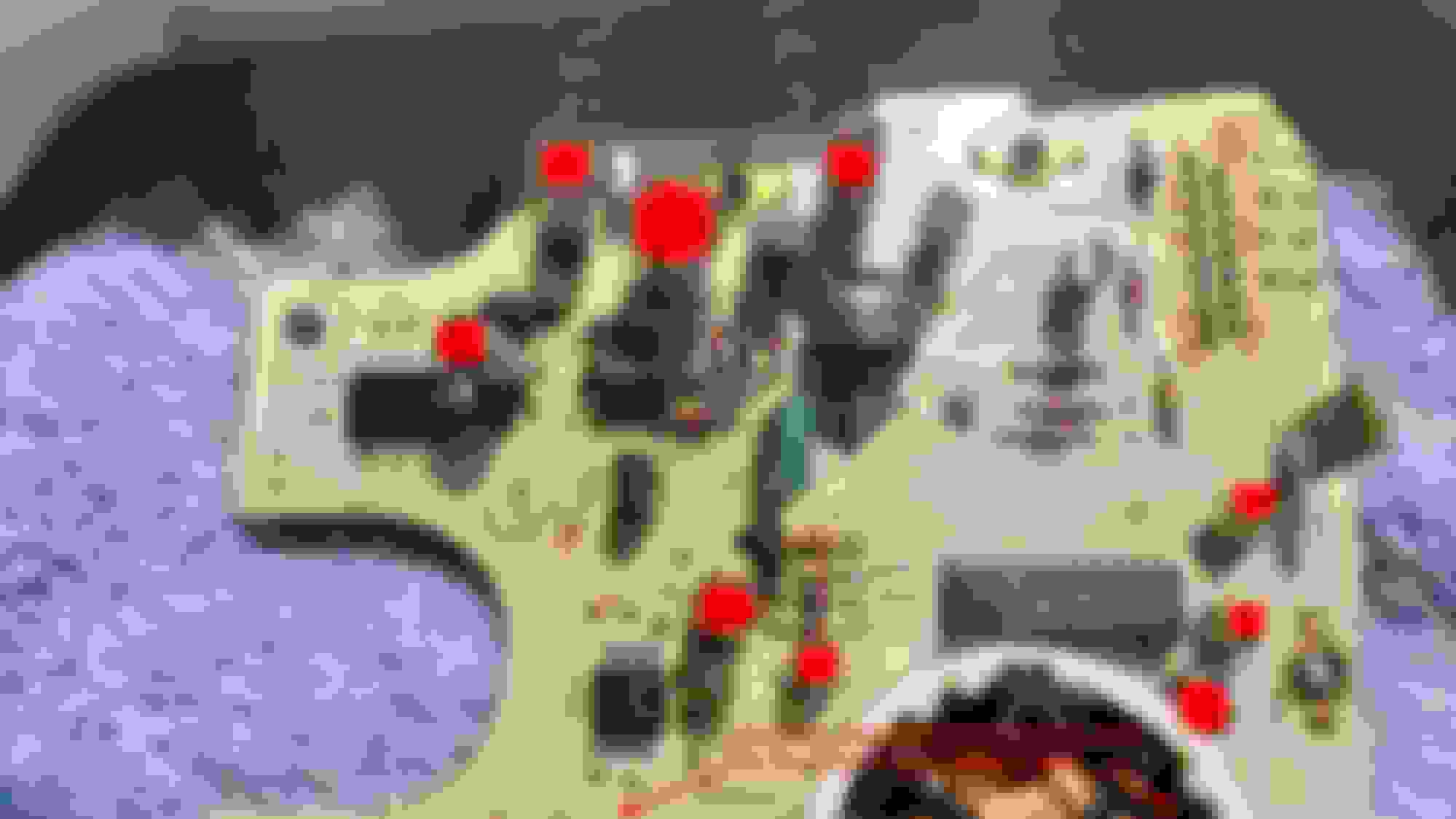
The red spots on the capacitors show which ones to replace. There are 2 other capacitors not shown. They are C11 and C12. They are located next to the LCD screen (odometer display).
Panasonic or Nichicon capacitors are excellent replacements. Follow the part numbers listed on the Speedometer parts thread. Make sure you use the short capacitors for C16 and C17 to keep the board looking similar.
@Thomasfd, off the cuff, I would recommend using the exact replacement Body CPU. There may be subtle differences between the 2 versions that would prevent a clean cross-over. What problem are you seeing with your Body CPU?
Finally i found the workshop manual for the European RX7. Is like Yours but in English.
I have to rename a lot of page and collect as a group of chapter because are still random page.
But in meanwhile if anyone should have need I can try to give some help.
Finally i found the workshop manual for the European RX7. Is like Yours but in English.
I have to rename a lot of page and collect as a group of chapter because are still random page.
But in meanwhile if anyone should have need I can try to give some help.
Where dis you find it! I also want one in english! 😅
Actually I paid at Mazda with a strange procedure Home - Mazda Motor Europe GmbH something like you pay the give you access to the documentation which was old and not logically organized.
Give me sometimes to organize all the page and I will give You a copy. I will put online for everybody.