
pics of my water injection set up!!

Senior Member
Joined: Nov 2001
Posts: 674
Likes: 0
From: Lynchburg, VA
forcefed1, you said you have a capacitor or some relay that will keep the water pump on for a number of seconds after your boost drops below the pressure point. I would consider this as an enhancement, I would probably run it for 6 seconds after Im off boost. Where did you get it, do you have any links/specs/brand names
well I searched and searched for a timer relay and came up with nothing. after a while I found a kit from MCM electronics called a vellman kit times relay it requires a bit of soldering knowledge and is designed for 0-5min times... I changed the cap on it to one 1/10th the size making my timer a 0 - 45 second timer allowing me more precise adjustment of the time. if you look it has an operation LED and both an on and off switch. I use the signal from the pressure switch to emulate the start switch signal and don't run a stop switch at all
http://www.velleman-kit.com/common/product.Aspx?id=8996 pretty sure I bought it through MCM electronics.
it was about 14$ for the kit takes about 10 min to solder it up
Thread Starter
Banned. I got OWNED!!!
Joined: Jun 2002
Posts: 3,323
Likes: 1
From: Buckhead
Im getting a little influence from some of the posts I'm reading and some of the research I'm doing. I'm considering designing a 2 stage system.
First one comes on at Low boost at low RPM's and sprays right into the exit to the intercooler. It would be a smaller nozzel, 2.5-3 GPH. This one would come on at low boost and run as long as I am in any boost, or Very low boost. The 2nd nozzel is exactly as it is now same location, comes on at 8 psi and joins the smaller injector but only after 4000 RPM. Its sort of a sequential water injection set up.
This would require a second selenoid, about 3 more feet of 3/8 fuel line and another LED for inside my car and another pressur switch. Cost will only be about $60.00 for the parts and some more labor to tap the IC endtank.... I wonder if its worth it to do this....
To be continued...
Rotary Enthusiast
Joined: May 2002
Posts: 971
Likes: 0
From: San Diego
Sounds like a nice plan if you can make it work...your setup right now looks pretty clean though, if I were you I'd just leave it how it is. 
My goodness! I've been whoring it up quite a bit lately...perhaps I'll step back and let some other people make some comments.

Btw Zerobanger, can you PM me all the links you have regarding WI so I can peruse them as well? Thanks
My goodness! I've been whoring it up quite a bit lately...perhaps I'll step back and let some other people make some comments.
Btw Zerobanger, can you PM me all the links you have regarding WI so I can peruse them as well? Thanks
Last edited by Chronos; Jul 22, 2003 at 01:09 AM.
Thread Starter
Banned. I got OWNED!!!
Joined: Jun 2002
Posts: 3,323
Likes: 1
From: Buckhead
Originally posted by Chronos
Sounds like a nice plan if you can make it work...your setup right now looks pretty clean though, if I were you I'd just leave it how it is.
My goodness! I've been whoring it up quite a bit lately...perhaps I'll step back and let some other people make some comments.
Btw Zerobanger, can you PM me all the links you have regarding WI so I can peruse them as well? Thanks
. Maybe today or tomorrow :P
Setup looks nice, I think I am going to get the Aquamist soon, did you notice any power increase at all, or is the benefit purely being able to run more boost safer and less wear on the engine?
Thread Starter
Banned. I got OWNED!!!
Joined: Jun 2002
Posts: 3,323
Likes: 1
From: Buckhead
Originally posted by Icemastr
Setup looks nice, I think I am going to get the Aquamist soon, did you notice any power increase at all, or is the benefit purely being able to run more boost safer and less wear on the engine?
Setup looks nice, I think I am going to get the Aquamist soon, did you notice any power increase at all, or is the benefit purely being able to run more boost safer and less wear on the engine?
Rotary Enthusiast
Joined: May 2002
Posts: 971
Likes: 0
From: San Diego
Originally posted by Zyon13B
So, because this cools the incoming air, does this lead to more HP also?
So, because this cools the incoming air, does this lead to more HP also?
EDIT: Sorry, I had to answer that one!
Senior Member
Joined: Nov 2001
Posts: 674
Likes: 0
From: Lynchburg, VA
in low boost the water will probably give you nothing extra especially at low RPM. in that situation your compressor is inside it's efficiency range so it's not pumping the heat... and your intercooelr is not being pushed to it's limits so it's pulling the ehat out. not to mention if your boost is set to 12 PSI you will hardly ever spend much time at say 6-12 psi. maybe a second ot 2. the boost will just quickly go right to 12... get what Im saying. the idea you have to run 2 nozzles for varying airflow conditions (i.e. rmp dependant not just boost) is a good one. I especially like it since that's what Im doing.
I have a few old pictures of my setup from before I finished it several months ago. I haven't driven the car in a few weeks (waiting on rear rotors) so i keep forgetting to take pictures.
when I do take them Ill post what I got
I have a few old pictures of my setup from before I finished it several months ago. I haven't driven the car in a few weeks (waiting on rear rotors) so i keep forgetting to take pictures.
when I do take them Ill post what I got
Thread Starter
Banned. I got OWNED!!!
Joined: Jun 2002
Posts: 3,323
Likes: 1
From: Buckhead
UPDATE:
I found that I needed to move my inline filter (3/8 fuel filter) to just after the water pump instead of before it. you can see from the pic that it was previously located after the water tank but before the water pump. I was having some issue with the the water not injecting at certain times. It had something to do with the weight of the filter causing the hose to restrict or the location. Im not sure which, but moving it after the pump solved the problem conclusively. It took me forever to figure where the problem was. The cool thing about this filter is that its glass and all you need to do to see if your water injection system is working properly is see if its filled with water. the line should maintain the water, if the filter does not have water in it, you know something is wrong.
Im considering also adding a 2nd nozzle to my intake tract. I have a 7 GPH nozzle now, I would just put a Y adapter at the exit of the selenoid, remove the current 7 GPH nozzle, replace that with a 3.5 GPH nozzle and directly across from it, put another 3.5 GPH nozzel. This may be more effective than having a single unit. Cost would be 7 bucks for the two nozzels, and 2 bucks for a y Connector. The other option is to get another selenoid and nozzle and put it at the exit of the intercooler.
Chronos...Interesting reading. Aquamist *DOES* say they prefer the nozzel to be at the intercooler exit *UNLESS* the intercooler suffers from heatsoak, which ours does.:
13. Where do I place the water jet?
Normally immediately after the intercooler unless the intercooler suffers from heat soaking such as the type that is fitted on top of the engine (Subaru, GTI-R, Toyota Celica and etc).
Thread Starter
Banned. I got OWNED!!!
Joined: Jun 2002
Posts: 3,323
Likes: 1
From: Buckhead
Originally posted by ZeroBanger
UPDATE:
I found that I needed to move my inline filter (3/8 fuel filter) to just after the water pump instead of before it. you can see from the pic that it was previously located after the water tank but before the water pump. I was having some issue with the the water not injecting at certain times. It had something to do with the weight of the filter causing the hose to restrict or the location. Im not sure which, but moving it after the pump solved the problem conclusively.
(===My water injection worked for the first week or so. Then I started to realize it wasn't injecting water. I first took off my elbow to check the nozzel. It was frustrating, cause I realized with the engine off if I by pass the pressure switch and intentionaly inject water it worked. But if the car was at IDLE it did not inject. So you can see it took me a while to realize that it wasn't injecting water, cause my test was with the engine off. The filter did not block the flow, no kinks in the hoses. My switches are all fine. The only thing I did not account for was the relay and the gauge of wire I was using. I think the wire gauge was fine, cause it used to work.===)
Long story short my new wiring diagram gets rid of the relay:

I think the relay got fried from the heat from the turbos and was malfunctioning. I realize there is no need for the relay, its just an extra piece. With the ignition wire, the system can only work when the key is turned, and with the pressure switch it will only activate at 8 PSI and the selenoid will only work when the pressure switch activates.
Anyway, there you have it. BTW...I parked my car for an hour and when I got in, the intake temps were 71C from the heatsoak. I pulled out my driveway hit 8 PSI for a second, the temps dropped to 65 Instanly. Then I hit 2nd gear and 8 psi for 2 seconds, the temps dropped to 60, then I hit 3rd gear and held 8 + Psi for 3 seconds and the temp dropped to 53. Then I turned around and parked in my driveway. I drove for less than 30 seconds and my heatsoaked temps dropped by 18 degrees Celsius!!!! This stuff is for real.
Last edited by ZeroBanger; Jul 29, 2003 at 10:14 PM.

Full Member
Joined: Oct 2001
Posts: 146
Likes: 0
From: Minneapolis, Minnesota
Originally posted by ZeroBanger
I think the relay got fried from the heat from the turbos and was malfunctioning. I realize there is no need for the relay, its just an extra piece. With the ignition wire, the system can only work when the key is turned, and with the pressure switch it will only activate at 8 PSI and the selenoid will only work when the pressure switch activates.
I think the relay got fried from the heat from the turbos and was malfunctioning. I realize there is no need for the relay, its just an extra piece. With the ignition wire, the system can only work when the key is turned, and with the pressure switch it will only activate at 8 PSI and the selenoid will only work when the pressure switch activates.
If the car won't start some day, you'll know where to look first.
Thread Starter
Banned. I got OWNED!!!
Joined: Jun 2002
Posts: 3,323
Likes: 1
From: Buckhead
Originally posted by bros0000
You are not entirely correct on that, the relay does serve a purpose, and that is to pull the required current straight from the battery, and not through the ignition circuitry. Whether that matters on our cars well, I guess you'll find out. If the car won't start some day, you'll know where to look first.
You are not entirely correct on that, the relay does serve a purpose, and that is to pull the required current straight from the battery, and not through the ignition circuitry. Whether that matters on our cars well, I guess you'll find out.
If the car won't start some day, you'll know where to look first.
Full Member
Joined: Oct 2001
Posts: 146
Likes: 0
From: Minneapolis, Minnesota
Originally posted by ZeroBanger
How would that keep the car from starting some day? The WI pump, at its peak takes 7 AMPS.
How would that keep the car from starting some day? The WI pump, at its peak takes 7 AMPS.
I'm sure you'll be fine, but I think instead of "I realize (sic) there is no need for the relay", more or less stating this as fact, a statement like "Although I have no electrical background, I don't believe there is a need for the relay" shows that your idea (in all likelyhood a perfectly good idea by the way) is just that and should by no means be considered "fact" without more research.
Originally posted by ZeroBanger
Im the first to say I dont know anything bout electricty
Im the first to say I dont know anything bout electricty
development
Joined: Aug 2002
Posts: 5,714
Likes: 7
From: Lafayette, LA
a thought...
add a nozzle to the IC duct, so when you're boosting +8psi, your IC gets a nice cool breeze running through it cooling the air that passes even more...
another thought...
is there a point where the air can become so cool, you actually start running too lean?
add a nozzle to the IC duct, so when you're boosting +8psi, your IC gets a nice cool breeze running through it cooling the air that passes even more...
another thought...
is there a point where the air can become so cool, you actually start running too lean?
Thread Starter
Banned. I got OWNED!!!
Joined: Jun 2002
Posts: 3,323
Likes: 1
From: Buckhead
Originally posted by bros0000
Have you measured the maximum current running through the circuit without water injection? If the norm is 5 amps and Mazda used parts typically rated for 5 amps, now you're burst firing 7 amps through the circuit every time your pump comes on. Stuff like this could lead to part failure over time.
I'm sure you'll be fine, but I think instead of "I realize (sic) there is no need for the relay", more or less stating this as fact, a statement like "Although I have no electrical background, I don't believe there is a need for the relay" shows that your idea (in all likelyhood a perfectly good idea by the way) is just that and should by no means be considered "fact" without more research.
For starters, the 20 amp fuse in your new diagram above serves no function...
Also, this entire thread is about RESEARCH. I said from the very beginning I am no expert on WI and I am learning and the point of this thread is to learn. All I can say is my WI was not working with the Relay, it worked for the first 7-10 days and then was on/off. I really think the engine bay is too hot for the relay.
I assumed the ignition circuit has to be rated at a high amp. Also, at one point I had my WI hooked up to my radio harness (batt and ignition with the relay) and when the WI would come on the radio would shut off. I believed it was overloading that circuit. If anyone has any facts as to why it wrong to do use the Ingition, please let me know.
I could have just as easlily hooked it up to the battery, but I want to eliminate the possiblity of the WI coming on when the car was turned off (if you connected the two leads from the pressure switch by accident the circuit will complete, this was the problem I had initially when the hood was closed it would do that, so I had to lower my pressure switch).
Thanks for your input
Thread Starter
Banned. I got OWNED!!!
Joined: Jun 2002
Posts: 3,323
Likes: 1
From: Buckhead
Originally posted by dubulup
a thought...
add a nozzle to the IC duct, so when you're boosting +8psi, your IC gets a nice cool breeze running through it cooling the air that passes even more...
another thought...
is there a point where the air can become so cool, you actually start running too lean?
a thought...
add a nozzle to the IC duct, so when you're boosting +8psi, your IC gets a nice cool breeze running through it cooling the air that passes even more...
another thought...
is there a point where the air can become so cool, you actually start running too lean?
also, the Water injection is designed to allow you to run lean without detonating. Im NOT telling you to get WI and lean out your car. If your WI fails your kinda screwed. Since the WI raises the octain of the gas and cools the chamber, running lean from the cool air should be ok (atleast that what I read). This is why everyone with WI can run 3-4 more lbs of boost with WI on the same same setup than without.
Maybe someone else can share an opinion on these 2 points?
Here's some help with the relay thing.
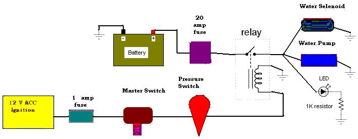
First, the purpose of a relay (in this case) is to allow a small amount of electricity (about 0.25 amps) to control a larger amount (7 amps). I don't know the limits of the ignition switch, however 7 amps is a large amount to add on top of the job that it currently does ... also, the master switch and pressure switch are probably not rated (or very near their limit) for 7 amps. Bottom line is that all three of these parts will suffer allot of wear. Hmm ... if the master switch is one of those big auto parts store types, it may be rated for 7amps. The relay (however) would allow you to use on of the small Radio Shack style switches.
So, here's the diagram ... I added an LED (light emitting diode). You can buy one of these (and the resistor) at Radio Shack for a couple of bucks. It's a "pump on" light ... just thought that I would complete the diagram.
Oh, I would recommend an automotive relay. That is on from an auto parts store designed to handle the heat.
James
Last edited by James Paventi; Jul 30, 2003 at 12:36 PM.
Thread Starter
Banned. I got OWNED!!!
Joined: Jun 2002
Posts: 3,323
Likes: 1
From: Buckhead
Originally posted by James Paventi
Here's some help with the relay thing.
First, the purpose of a relay (in this case) is to allow a small amount of electricity (about 0.25 amps) to control a larger amount (7 amps). I don't know the limits of the ignition switch, however 7 amps is a large amount to add on top of the job that it currently does ... also, the master switch and pressure switch are probably not rated (or very near their limit) for 7 amps. Bottom line is that all three of these parts will suffer allot of wear. Hmm ... if the master switch is one of those big auto parts store types, it may be rated for 7amps. The relay (however) would allow you to use on of the small Radio Shack style switches.
So, here's the diagram ... I added an LED (light emitting diode). You can buy one of these (and the resistor) at Radio Shack for a couple of bucks. It's a "pump on" light ... just thought that I would complete the diagram.
Oh, I would recommend an automotive relay. That is on from an auto parts store designed to handle the heat.
James
The pump has the following stats:
Model 8000-543-236
Description 1.8 GPM open flow, Viton� valves, Santoprene� diaphragm, 60 PSI Demand Switch, 3/8" NPT-Female ports
Voltage 12 VDC
PSI 20 40 60
BAR 1.4 2.8 4.1
GPM 1.26 1.14 1.02
L/min 4.7 4.3 3.9
Amps 5.0 6.2 7.3
No problems yet, but im researching for sure thanks for sharing!
Thread Starter
Banned. I got OWNED!!!
Joined: Jun 2002
Posts: 3,323
Likes: 1
From: Buckhead
Originally posted by James Paventi
Here's some help with the relay thing.
First, the purpose of a relay (in this case) is to allow a small amount of electricity (about 0.25 amps) to control a larger amount (7 amps). I don't know the limits of the ignition switch, however 7 amps is a large amount to add on top of the job that it currently does ... also, the master switch and pressure switch are probably not rated (or very near their limit) for 7 amps. Bottom line is that all three of these parts will suffer allot of wear. Hmm ... if the master switch is one of those big auto parts store types, it may be rated for 7amps. The relay (however) would allow you to use on of the small Radio Shack style switches.
So, here's the diagram ... I added an LED (light emitting diode). You can buy one of these (and the resistor) at Radio Shack for a couple of bucks. It's a "pump on" light ... just thought that I would complete the diagram.
Oh, I would recommend an automotive relay. That is on from an auto parts store designed to handle the heat.
James
Here's some help with the relay thing.
First, the purpose of a relay (in this case) is to allow a small amount of electricity (about 0.25 amps) to control a larger amount (7 amps). I don't know the limits of the ignition switch, however 7 amps is a large amount to add on top of the job that it currently does ... also, the master switch and pressure switch are probably not rated (or very near their limit) for 7 amps. Bottom line is that all three of these parts will suffer allot of wear. Hmm ... if the master switch is one of those big auto parts store types, it may be rated for 7amps. The relay (however) would allow you to use on of the small Radio Shack style switches.
So, here's the diagram ... I added an LED (light emitting diode). You can buy one of these (and the resistor) at Radio Shack for a couple of bucks. It's a "pump on" light ... just thought that I would complete the diagram.
Oh, I would recommend an automotive relay. That is on from an auto parts store designed to handle the heat.
James
My setup has the pump in the trunk, and the battery is in the engine bay. I may at some point get a new relay and try it with a better gauge wire. When I re-wired my setup yesterday I did change the gauge to 14 gauge. I dont know what was on there, but it was thinner.
Thread Starter
Banned. I got OWNED!!!
Joined: Jun 2002
Posts: 3,323
Likes: 1
From: Buckhead
I hope this is understandable. Feel free to ask any questions. Its the best I can do to get you guys started. I'm getting alot of PM's and trying my best to help everyone. Keep in mind, once you buy the selenoid, pump and pressure switch you will realize how all this goes together. When you go to homedepot to buy the brass fittings, print off the pictures below that show the brass fittings.
This was my real influence. This guy was influenced by the turbomirage site.
http://members.aol.com/raydorman
Here is a pic of the pressure switch. $25.00
http://members.aol.com/raydorman/pages/hobbs_switch.htm
Here is a pic of the selenoid. NOTE THE CONNECTORS, this is what you need. about selenoid is about $30.00, connectors are about $2.00 each.
http://members.aol.com/raydorman/pag..._noz_parts.htm
Here is a pic of the pump. Note again, the connectors. the only difference between this and mine, is that on the OUT (exit) side of the pump I used a 3/8 NPT instead of barbed hose. I connected one end of the 3/8 NPT to the exit side of the pump, then connected the 90 degree female 3/8 NPT elbow to that. Then I connected a 3/8 barbed to that (the same piece that is in the entrance. I needed to do this because because I mounted it in the jack area. It does not slow down the flow of water)
http://members.aol.com/raydorman/pages/pump.htm
This is another resource. I warn you the brass connectors are all wrong, dont even look at them.
http://www.turbomirage.com/water3.html
For the spray nozzle goto www.mcmastercarr.com. The part # I used is 3178K76 its 6.32 GPH @ 40 PSI.
For the pump goto here
http://www.northerntool.com/webapp/w...4&categoryId=0
for the pressure switch goto NAPA auto parts and ask for a hobbs pressure swtich #701-157
Goto pepboys and get 3/8 fuel line for 1.19 per foot. Get 16 feet if you plan on doing my installation. Some of the websites say to get Fuel injector hose. It costs 4.50 per foot and IMHO is not necessary.
Ok, now you need a Tank of some kind. You can see my tank from this pic:

You can pic that tank up at Kragen Auto parts. It costed me 8.50. You need to do some slight modifications. I took the lid, drilled 3/8 inch hole, put some brass connector and a 90 elbow with another brass connector to the hose. then sealed it with silicon. You can use any tank you like.
You should use a fuel filter for the water. I *REALLY* like this one. Here is a close up. Notice in the pic above I used to have it prior to the pump. I now moved it after. You can always check to see if your WI is injecting water. When you stop your car, water should be in the filter. It will also keep your injectors from getting clogged. Cost is about 9.00 from monument car parts. you can use any 3/8 inline fuel filter.

You can get 3/8 inch Led indicators from Kragen Auto Parts. You can see the switch in the middle and the Amber and the Green 3/8 LED

The Amber LED is set to my ignition wire I have a switch on the other side of the ignition wire. When the ignition is on and the switch is on, this LED will light Amber. This is important, so I know when I really push my car hard that the water injection is ARMED. The second led, the green one is conected to line going the pump AFTER the fuse. Its obviously placed after the fuse so it can tell me that the system is running. Otherwise, if the fuse has blown the green light would still come on. The green light only comes on when the pressure switch completes the circuit. In my case 8 PSI. When I first installed the system, I had mounted my pressure switch too high in the engine bay. The hood closed and probably had less than a 1/8 inch gap before touching the pressure switch. When I hit a bump it would cause the hood to press against the switch completing the circuit.YOU NEED A LIGHT INDICATOR TO SHOW YOU THAT THE SYSTEM IS RUNNING I cant stress that enough. It was 100F outside when I noticed my green light on. I was on the highway on my way to a local rx7 meet and I looked at my air temp and it was 15C (about 60F). Had I not had that indicator its possible I could have hydrolocked my engine. You do not hear the pump running in the car, so you need to know whats going on.
You can buy any toggle switch from the store and place inbetween the ignition. The toggle switch is about 2 bucks, the leds are about 2.50.
You can goto to that turbomirage or the raydorman site and get a full parts list, keep in mind both those sites have different electrical diagrams and mine is different than both of those. I eliminated the relay and like it much better. My electrical is below. Please note I have to add the LED indicators still, but the basic is here
This was my real influence. This guy was influenced by the turbomirage site.
http://members.aol.com/raydorman
Here is a pic of the pressure switch. $25.00
http://members.aol.com/raydorman/pages/hobbs_switch.htm
Here is a pic of the selenoid. NOTE THE CONNECTORS, this is what you need. about selenoid is about $30.00, connectors are about $2.00 each.
http://members.aol.com/raydorman/pag..._noz_parts.htm
Here is a pic of the pump. Note again, the connectors. the only difference between this and mine, is that on the OUT (exit) side of the pump I used a 3/8 NPT instead of barbed hose. I connected one end of the 3/8 NPT to the exit side of the pump, then connected the 90 degree female 3/8 NPT elbow to that. Then I connected a 3/8 barbed to that (the same piece that is in the entrance. I needed to do this because because I mounted it in the jack area. It does not slow down the flow of water)
http://members.aol.com/raydorman/pages/pump.htm
This is another resource. I warn you the brass connectors are all wrong, dont even look at them.
http://www.turbomirage.com/water3.html
For the spray nozzle goto www.mcmastercarr.com. The part # I used is 3178K76 its 6.32 GPH @ 40 PSI.
For the pump goto here
http://www.northerntool.com/webapp/w...4&categoryId=0
for the pressure switch goto NAPA auto parts and ask for a hobbs pressure swtich #701-157
Goto pepboys and get 3/8 fuel line for 1.19 per foot. Get 16 feet if you plan on doing my installation. Some of the websites say to get Fuel injector hose. It costs 4.50 per foot and IMHO is not necessary.
Ok, now you need a Tank of some kind. You can see my tank from this pic:
You can pic that tank up at Kragen Auto parts. It costed me 8.50. You need to do some slight modifications. I took the lid, drilled 3/8 inch hole, put some brass connector and a 90 elbow with another brass connector to the hose. then sealed it with silicon. You can use any tank you like.
You should use a fuel filter for the water. I *REALLY* like this one. Here is a close up. Notice in the pic above I used to have it prior to the pump. I now moved it after. You can always check to see if your WI is injecting water. When you stop your car, water should be in the filter. It will also keep your injectors from getting clogged. Cost is about 9.00 from monument car parts. you can use any 3/8 inline fuel filter.
You can get 3/8 inch Led indicators from Kragen Auto Parts. You can see the switch in the middle and the Amber and the Green 3/8 LED
The Amber LED is set to my ignition wire I have a switch on the other side of the ignition wire. When the ignition is on and the switch is on, this LED will light Amber. This is important, so I know when I really push my car hard that the water injection is ARMED. The second led, the green one is conected to line going the pump AFTER the fuse. Its obviously placed after the fuse so it can tell me that the system is running. Otherwise, if the fuse has blown the green light would still come on. The green light only comes on when the pressure switch completes the circuit. In my case 8 PSI. When I first installed the system, I had mounted my pressure switch too high in the engine bay. The hood closed and probably had less than a 1/8 inch gap before touching the pressure switch. When I hit a bump it would cause the hood to press against the switch completing the circuit.YOU NEED A LIGHT INDICATOR TO SHOW YOU THAT THE SYSTEM IS RUNNING I cant stress that enough. It was 100F outside when I noticed my green light on. I was on the highway on my way to a local rx7 meet and I looked at my air temp and it was 15C (about 60F). Had I not had that indicator its possible I could have hydrolocked my engine. You do not hear the pump running in the car, so you need to know whats going on.
You can buy any toggle switch from the store and place inbetween the ignition. The toggle switch is about 2 bucks, the leds are about 2.50.
You can goto to that turbomirage or the raydorman site and get a full parts list, keep in mind both those sites have different electrical diagrams and mine is different than both of those. I eliminated the relay and like it much better. My electrical is below. Please note I have to add the LED indicators still, but the basic is here