When you click on links to various merchants on this site and make a purchase, this can result in this site earning a commission. Affiliate programs and affiliations include, but are not limited to, the eBay Partner Network.
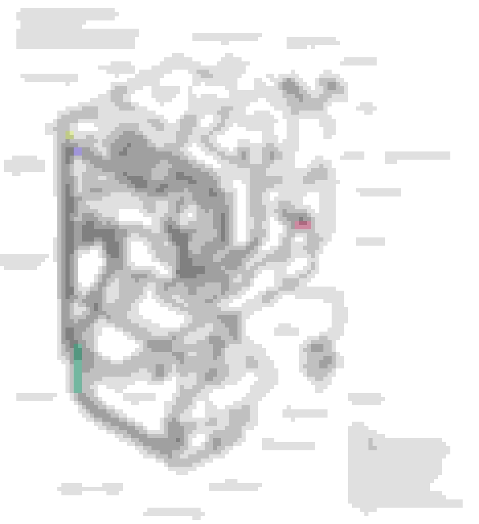
Hi, I have a 2002 FD3S and I was checking if the car have any Codes and it appears it have the Code32 which means something with the Solenoid Valve (Switching). I was looking at the diagram of the olders models and it runs a hose from the ACV to this solenoid but in my model the hose from the ACV runs to the "Blackbox" and inside the blackbox I can't find any Solenoid Valve (Switching). Any idea how to solve this issue? car is stock except for a recently installed downpipe and intake.
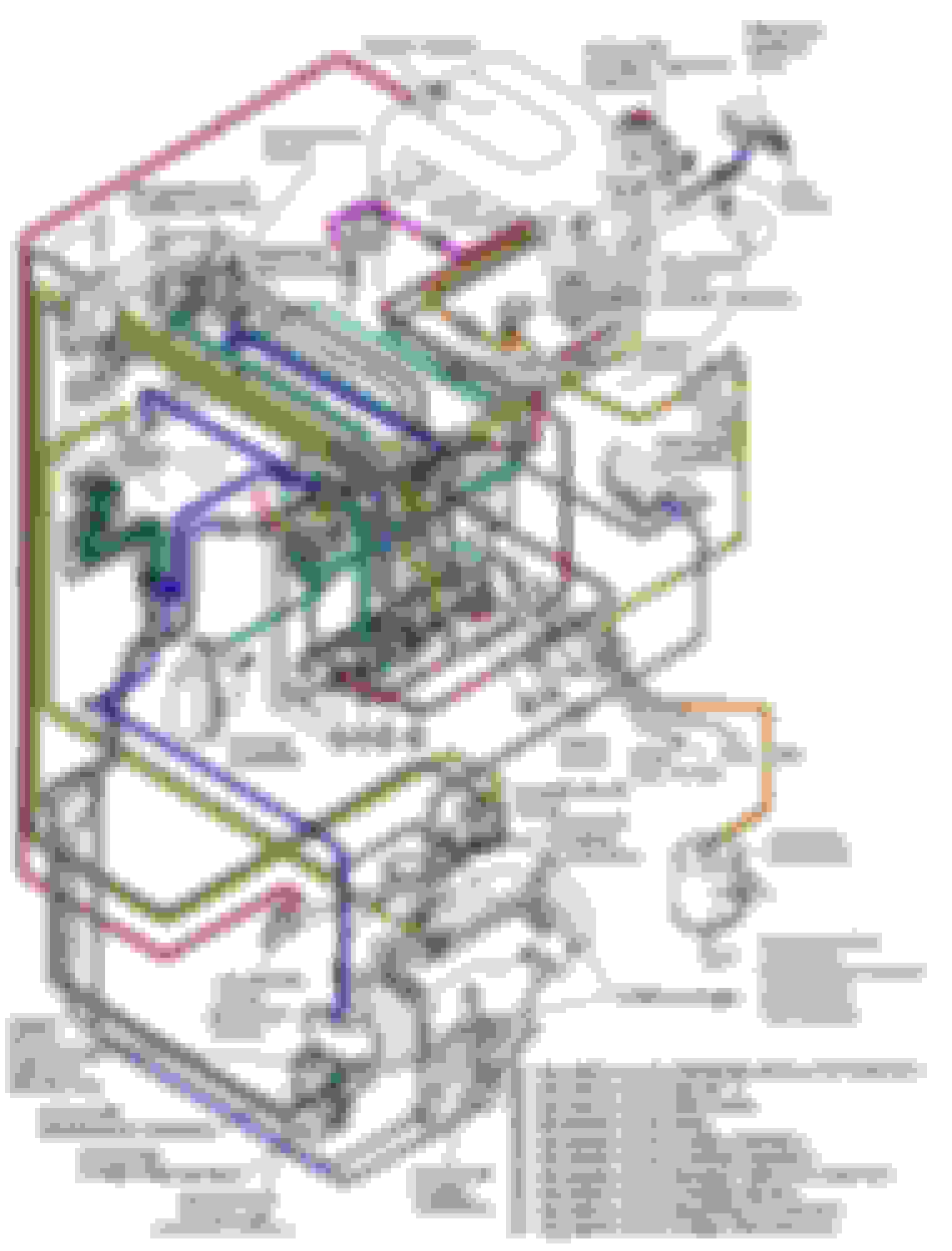
Below I will post the diagram from older models and my blackbox for refference:
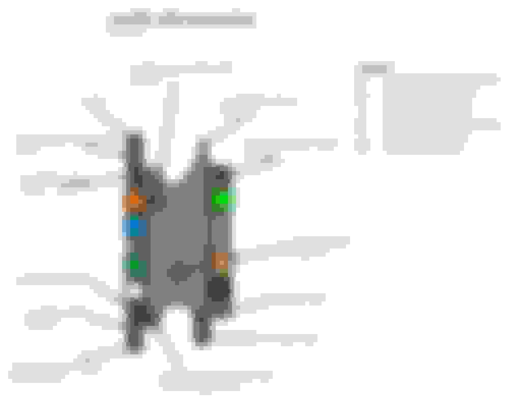
I'd be running a meter over it first, duty cycle for one of those is hardly onerous, so an odd failure. Often they use 323 replacement solenoids down here for those because of availability. Green next to white btw.
Thanks for the responses; another silly question, can I use and run the car with this issue with no problem with the performance of it? since I'm changing my turbos (leaking oil) to BNR Stage3 twins and making alot of work with the car, I wanted to buy a new blackbox because this will be already the second time I need to open it for a bad solenoid but I'm not sure if it's worth the buy ($800 for new blackbox) or eliminate all the emissions related (simplified the system).
you can either replace the solenoid FEGC-18-741 or the whole black box N3F1-20-341
actually you should make sure the wiring is ok first
I noticed that on the Series 8 Vacuum Diagram, "FEGC-18-741" is not displayed, and you said you can either replace that, or the black box. I have a series 8 and need to replace all my solenoids right now, only ones I haven't purchased were the FEGC-18-741, and the Black Solenoid Box. Was going to get the box, but is the FEGC-18-741 on a series 8 as well, or is it a part of the black box for this series?
Check the resistance of the solenoid, if it checks out for resistance and clicks ok when you short the terminals with a 9v battery then check the loom for continuity back to the ECU.
New black boxes are not overly expensive and can save a lot of future headaches.
Are you sure that solenoid is in the black box? What about the solenoid on the ACV?
That's one of the two turbo control solenoids. Both ACV solenoids are in the black box. They are not too bad to split down and swap out. They are much more common solenoids than the ones used in the earlier fd's.
Also, the "switching" solenoid is the dark green one in the last of your diagrams. One from bottom on the left labelled up as "port air", same thing.
2 Pages 2 through 13
Solenoid Box pictures, Labels, Descriptions, Where every nipple goes to, and paintshop cut excerpts of the Japanese Series 8 factory service manual to ensure 100% accuracy for black box.
If your FD twin turbo is not playing the 10-8-10 stock boost curve or is playing up in various gears/conditions make sure you check all these solenoids and vacuum leads and especially check valves, vacuum host splits and connections.
3 Pages 14 onwards
How to remove, disassemble, check/replace solenoid valves INSIDE black box, how to reassemble and refit
If you’ve checked all the external stuff (hoses, piping, wastegate and precontrol, ACV-mounted vaccuum side solenoid (1 of 2) then youre forced here, to open this box up and find/replace the faulty solenoid.
2 Pages 17 to 23 – BLACK BOX SERVICING
How to remove, disassemble, check/replace solenoid valves INSIDE black box, how to reassemble and refit
If you’ve checked all the external stuff (hoses, piping, wastegate and precontrol, ACV-mounted vaccuum side solenoid (1 of 2) then youre forced here, to open this box up and find/replace the faulty solenoid.
1.Fuel pressure regulator solenoid
2.secondary relief solenoid
3.port air control solenoid
4.charge control solenoid
5.double throttle control solenoid
6.Turbo control solenoid (1 of 2)
7. Charge relief solenoid
(8. Bolted to ACV= turbo control 2of2)
These solenoids should test with 37-41 ohms of resistance when cold and reach up to 45 ohms of resistance when warmed/hot. Higher than 50 when hot or 41 when cold indicates probable failure. Open circuit or values such as 80ohms=failed.
5 to Charge Control Actuator /CCA (routes to green metal pipe on next diagram) (see appendix A: CCA) 4 to Charge Relief Valve /CRV (routes to red metal pipe on next diagram) (see appendix A: CRV) 9 to ‘manifold’ (which is 2ndry Turbo pressure side Y pipe, routes to blue metal pipe on next diagram)
6 to turbo control actuator via solid piping (1 of 2) (see appendix D for JDM diagram in full)
8 to turbo control solenoid bottom port (2 of 2)
2 to air control valve
[img]file:///C:/Users/Davis/AppData/Local/Temp/msohtmlclip1/01/clip_image017.jpg[/img]
{Sorry: I had to delete the rest of this due to problems uploading the pictures. I was blocked from opening the files]
Last edited by Redbul; Dec 6, 2020 at 04:28 PM.
Reason: Import Images