When you click on links to various merchants on this site and make a purchase, this can result in this site earning a commission. Affiliate programs and affiliations include, but are not limited to, the eBay Partner Network.
I figured many have received or installed their Vmount already and a thread would help me and whoever is going to do the install. I am in the middle of it and stuck on the ac lines. It looks like you have to remove the low pressure line that runs into the compressor to install the radiator exit hose. If you were able to keep it...how did you run your lines.
Here is a picture an low side pipe that blocks where the radiator exit hose suppose to go:
For those that want airtight ducting for the IC and radiator and find the Greddy supplied sheet metal a little wanting in that regard, here are the templates for a tight ducting arrangement that I made. Pretty obvious, but the heat transferred with an air-to-air heat exchanger is proportional to mass flow, so the more air flow the better. The Greddy setup lets air escape all over the place. And one sheet metal piece they supply seems purposely designed to block air from the back quarter of the IC(!)
This design is for the following setup, but is easily modifiable for others:
- Greddy Vmount
- JP3 RX8 A/C conversion
- JP3 PC680 battery box (although my battery is a slightly smaller Braille. Really, Lithium batteries are awesome - they are like a fifth the weight and probably as powerful a a full-size lead-acid.)
JP3 IC mount that shifts it over a bit to make room for the battery box
To avoid blocking any fins and ensure the entire IC can be used, the IC is sealed along the front and back side vertical surfaces. The left and right seals assume some tall soft foam (e.g. 5/8 or higher) to seal against the end caps. I used the foam strip that came with the Greddy vmount kit here.
Suggestions:
- This isn't perfect and we are talking sheet metal so not really precise and every car is likely a little different. Be prepared to tweak and adjust for your setup.
- Make the templates with stiff poster-type paper first, check fitment, then cut and bend the sheet metal.
- The .04" sheet metal (same as the Greddy supplied) can be cut with shears with difficulty if the shape is first roughed out with a 24 tooth/in blade in a mini sawzall or equivalent. Have to be careful with this...
- I used a cheap 18" harbor freight sheet metal brake for as many of the bends as I could. It helps to be as precise as possible, so play with that on some scrap pieces first to see where to place a bend to get a certain dimension.
- The templates don't show the bolt holes necessary to put it together as this is best figured out after the sheet metal is bent, so one can drill the holes through both mated pieces at the same time.
- I don't like assembling with a loose nut and a loose bolt, so used press-fit nuts wherever possible. I also used rivet nuts in a few spots (at those left and right wings at the top of the radiator, and the mount tabs on the front of the IC) to further minimize loose nuts.
- If a hole drilled for a press-fit nut ends up too large, tape some 3M high temp flue tape over the hole to add material, press the nut in, then tape over the top of the nut with the flue tape to help keep it in place. This is the same tape I use on wheel weights for the track. This worked really great and saved having to remake some of the pieces.
- Think of all the ways air can escape without going through one of the heat exchangers, and block them off. Use 1/6" ultra soft foam between sheetmetal pieces. Put foam on the sides of the JP3 AC condenser mounts. The Greddy radiator doesn't have fins all the way up to the end caps - big air gaps there so block those with high-temp foam. Etc. Etc.
- Use ultra-soft high-temp adhesive backed foam, see below for some examples. I tried to get foam that could handle at least 220F.
- Wrap the AC hoses with some 1" foam so it seals tightly where the hoses go through the side pieces.
Some McMaster PNs that I used:
88895K103 .04" aluminum sheet
97648A440 press fit nuts
98005A440 low profile rivet nuts (these need a rivet nut tool)
97654A378 M6 button heads for the exposed surfaces. For the IC front seal, grind two of these down almost flat because you will need to put foam over top of them.
90166A143 M6 Flange head 10mm for the bolts holding the front IC-to-air-guide to the horizontal and side pieces (hard to get a allen head in there)
92525A139 Sheet metal screws for attaching to the air guide (what Mazda calls that rounded black plastic piece below the reinforcement bar)
86115K71 High temp poly foam (buying sheets seemed to be the cheapest way to get strips). The poly foam is A LOT softer than the EPDM (look up the PSI to compress). If I were to do it over, I might use this stuff everywhere.
1566N138 Ultra-Weather-Resistant EPDM Foam 1/4" by 2". I used this across the top cap of the radiator to insulate that from the IC a little.
I had a lot of other high temp foam already in the garage that I used extensively so you will need more than just this stuff. Don't have part numbers for those.
Anyway, this isn't a full how-to and if I did it again I'd do a few things differently (e.g. the wings on the rear IC seal should be longer so the bolts aren't so close to the radiator) but this should get someone interested 90% of the way there.
And please ignore the kludgy IC piping from the twins. I'm waiting for a single turbo to show up.
Loosen the line at the connection by the passenger frame rail and rotate it down. Then push the line forward and under the support bar. Secure it there with insulated clamps.
Last edited by IRPerformance; Dec 1, 2015 at 12:38 PM.
You also have to remember that this kit was designed for a right hand drive car. The RHD cars don't have an AC line there.
That being said, you will have to get a little creative with some of the work. You should be able to CAREFULLY manipulate the AC lines without disconnecting them or having to discharge the system.
Also, to the original poster, the vacuum cap on the thermostat housing that originally went to the AST will fail. Vacuum caps can't handle the heat and pressure of coolant, and will eventually rupture. Best way is to have that hole welded shut, second best is to remove the pressed in hose barb and drill/tap the hole for a plug, third best is a piece of coolant hose with a bolt or plug stuck in it and hose clamped. Option 3 isn't glamorous but it does work long term.
I was about to make a similar thread. I'm on the same step.
Did you get a chance to install the lines yet? Any pictures?
No pictures yet..im actually on vacation and probably wont get back to it til next week.
Dale..thanks for the tip. I actually received the car like that from the builder/seller and never really thought about that vacuum cap. That will be something I need to address since I have the coolant system drained anyway.
I wasn't even able to get that far. The aluminum brackets that are suppose to attach in place of the stock mount don't even line up. Drivers side lower bracket on the condenser is an inch (lower or higher I don't remember) than the drilled holes on the bracket. You can't drill holes into the bracket to adjust because there is a bend in the way.
Next time I'm back in the garage I'll grab some pictures.
in the instructions there was a picture on the right hand side of the radiator and a circle around a dot. Are we supposed to drill a hole on the side of the radiator(radiator frame and not radiator itself). That was what I interpret it as but was not sure and didn't know why they would need it. I am probably wrong but what are we suppose to do for that step?
The kit with part number ending in "02" includes a hot side elbow that bolts onto the Efini y-pipe which is originally a part found on car model years on and after 1999. If you have this kit and are installing it onto a USDM car, you'll need a) the Efini y-pipe or b) a hot side elbow that uses the stock style coupler.
I am running the stock twins but it was wired nonsequentially when I received the car. I am trying to hook up the dual intake for the car and trying to figure out what goes into the 2 tubes coming out of each intake. I have the left tube of the bottom intake tube connecting to the bov or crv(can't recall which one), and the left tube of the second upper I ntake connected to the other crv/bov. So I have two right tubes (1 from the upper and 1 from the bottom intake) left and do not know what suppose to go there. I have emissions removed so I am assuming the bottom intake right tube was suppose to go to the air pump. Where is the right tube of the upper intake connect to? or do I just plug both of these tubes?
I am running the stock twins but it was wired nonsequentially when I received the car. I am trying to hook up the dual intake for the car and trying to figure out what goes into the 2 tubes coming out of each intake. I have the left tube of the bottom intake tube connecting to the bov or crv(can't recall which one), and the left tube of the second upper I ntake connected to the other crv/bov. So I have two right tubes (1 from the upper and 1 from the bottom intake) left and do not know what suppose to go there. I have emissions removed so I am assuming the bottom intake right tube was suppose to go to the air pump. Where is the right tube of the upper intake connect to? or do I just plug both of these tubes?
You'll have to block it off. The open pipe on the lower intake is probably for the air pump. The upper intake I forgot what it was for. But it was a hard line that wrapped around the upper intake manifold up against the fire wall.
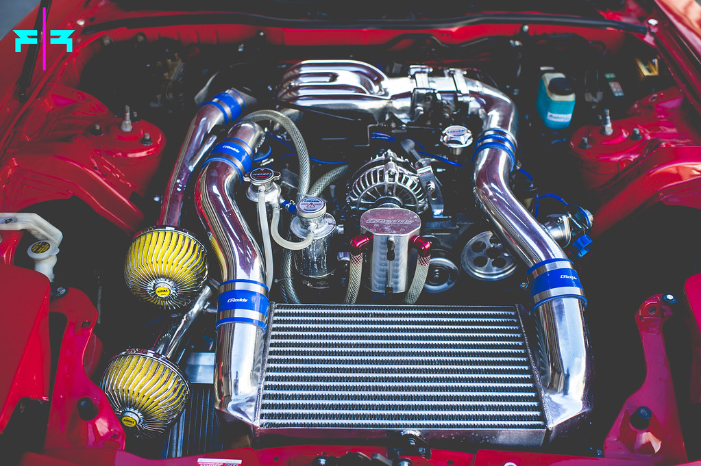
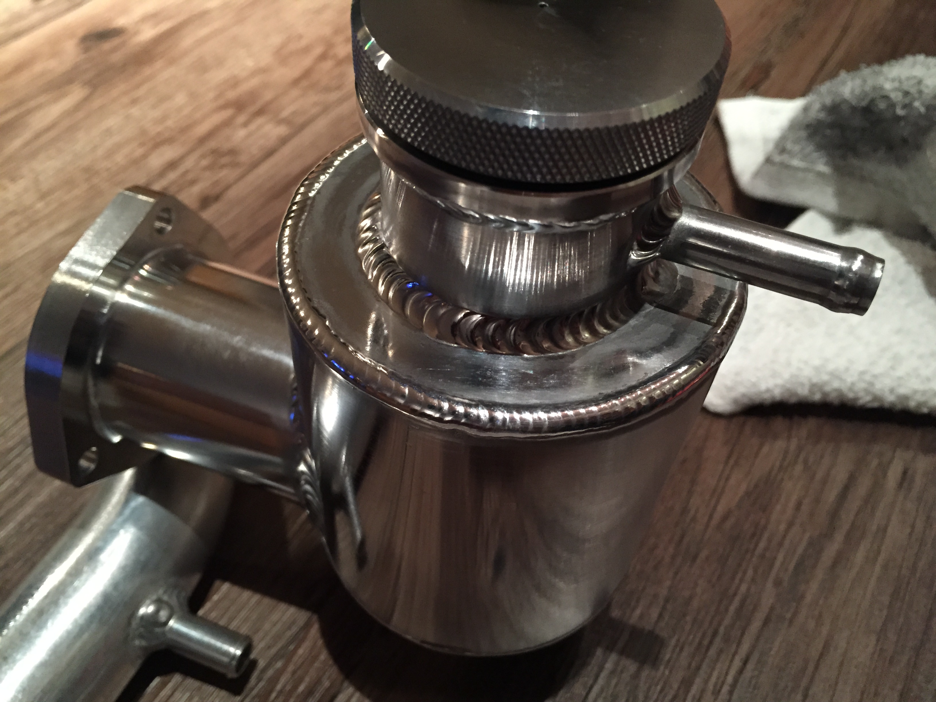
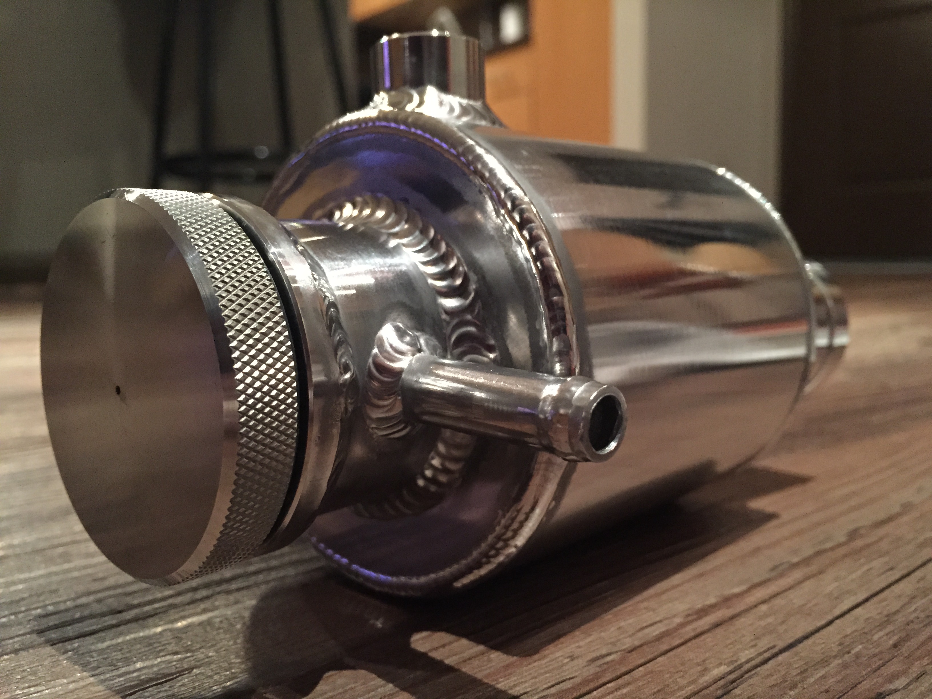
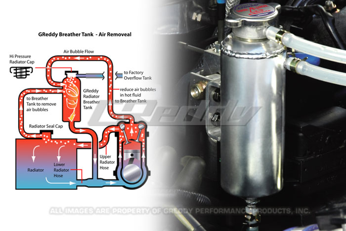
Driftfc3s, what's the story on the coolant tank that mounts where the filler neck / thermostat housing was located? Wanted to call it an AST tank but looks like a separate AST is plumbed in to the left. Greddy has one on the car in their promotional literature but I haven't seen anything else about it.
just realize it after you posted that there were two types! My order history has the kouki version. Wished I paid attention when I ordered it
Does anyone know where to get a 1 inch vacuum cap or a plug? I just need to plug one of the arms for the lower intake that was suppose to connect to the airpump.
Driftfc3s, what's the story on the coolant tank that mounts where the filler neck / thermostat housing was located? Wanted to call it an AST tank but looks like a separate AST is plumbed in to the left. Greddy has one on the car in their promotional literature but I haven't seen anything else about it.
It is a "Radiator Outlet Tank" made by AutoStaff. Same exact piece by Revolution, but without the branding. It was recommended to me by Tani-San of Pro Shop Fukuoh, and there are two types, one that just replaces the stock OEM piece and another that replaces the AST at the same time. I opted for the OEM replacement and paired it with the Greddy/Trust radiator breather tank.