
Stock ECU Real-Time Tuning / Datalogging

Thread Starter
Joined: Dec 2001
Posts: 10,630
Likes: 3
From: NY, MA, MI, OR, TX, and now LA or AZ!
While IC605 will be free afterwards -- it's of no use really, as the UART wouldn't fit in the slot anyway -- so a daughterboard is a must. Thus, what the schematic represents. The daughterboard will plug into sockets that replace IC609 and IC604. The modifications to the ECU itself will be of course installing those sockets, and then running some wires to connect some missing logic from the CPU -- such as the logic to enable the EPROM for the 0x8000 address space, writing, reset (for the UART), and possibly the output enable as well. They're fairly simple mods to the ECU itself and reversible if so desired.
Thread Starter
Joined: Dec 2001
Posts: 10,630
Likes: 3
From: NY, MA, MI, OR, TX, and now LA or AZ!
Thanks to Aron (wthdidusay82), I was able to get the N332 S4 TII EPROM, bringing my collection thus far to:
N326 (0275/0285)
N326 (0276/0286)
N332 (0375/0385)
N333 (0376/0386)
N374 (1064)
Now, onto prepping the ECU. I'm working with an N333 ECU -- others are slightly different as to the location of certain pads on the board, but they're in the same general area.
This is what you'll be starting with. Simply desolder each of the labeled chips from the board.
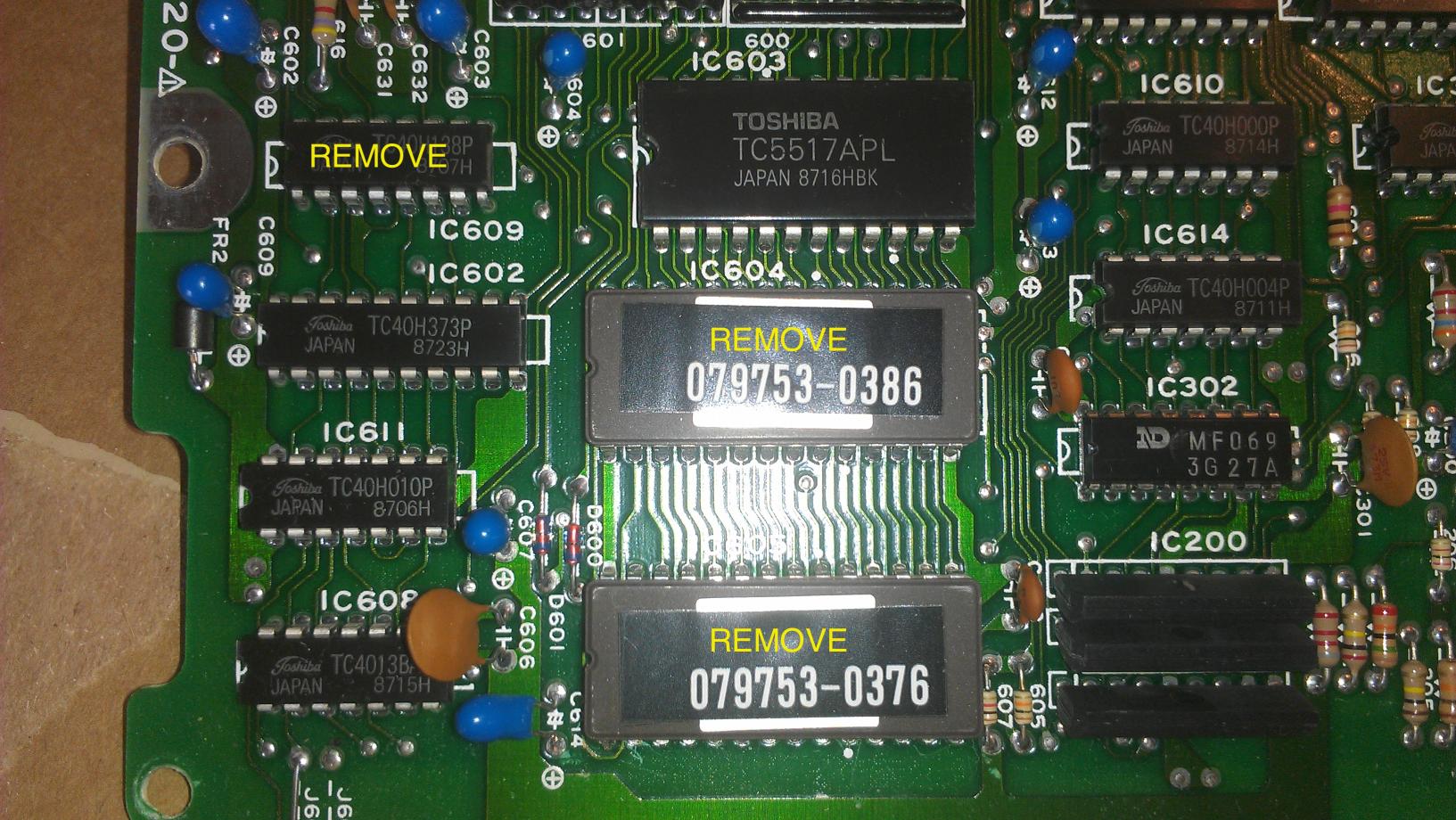
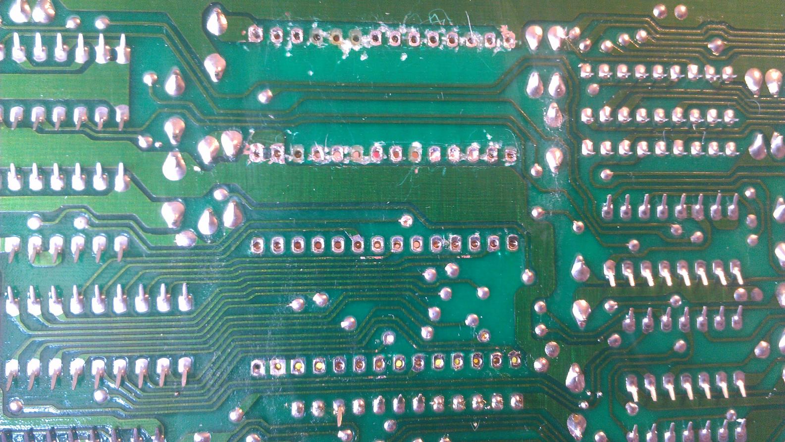
BE CAREFUL WITH YOUR DESOLDERING!
It is very easy to mess up the board and sockets if you are not careful, as you can see on this board (the offender shall go unnamed... )
)
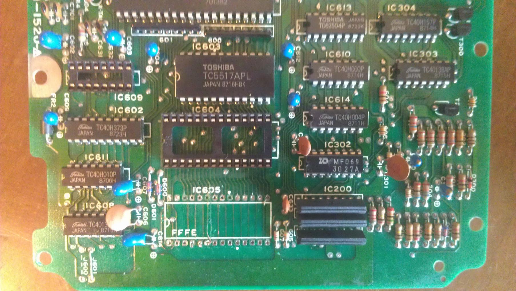
Afterwards, install sockets in the location of IC604 and IC609. I used Digikey part # DILB28P-223TLF and ED3046-5-ND.
Next, we need to solder on some jumper wires to gain access to certain functions of the CPU (such as /WR, A15 address chip enable to support the larger rom, and RESET). There is also one location where you will need to cut the trace on the PCB board with a razor blade/sharp knife. This won't hurt the ECU if you decide to go back, as these pins are otherwise unused. This image explains the location of the wires and their corresponding functions (in the case of /WR, you can also verify the correct pin by checking continuity to pin 21 of the SRAM module).
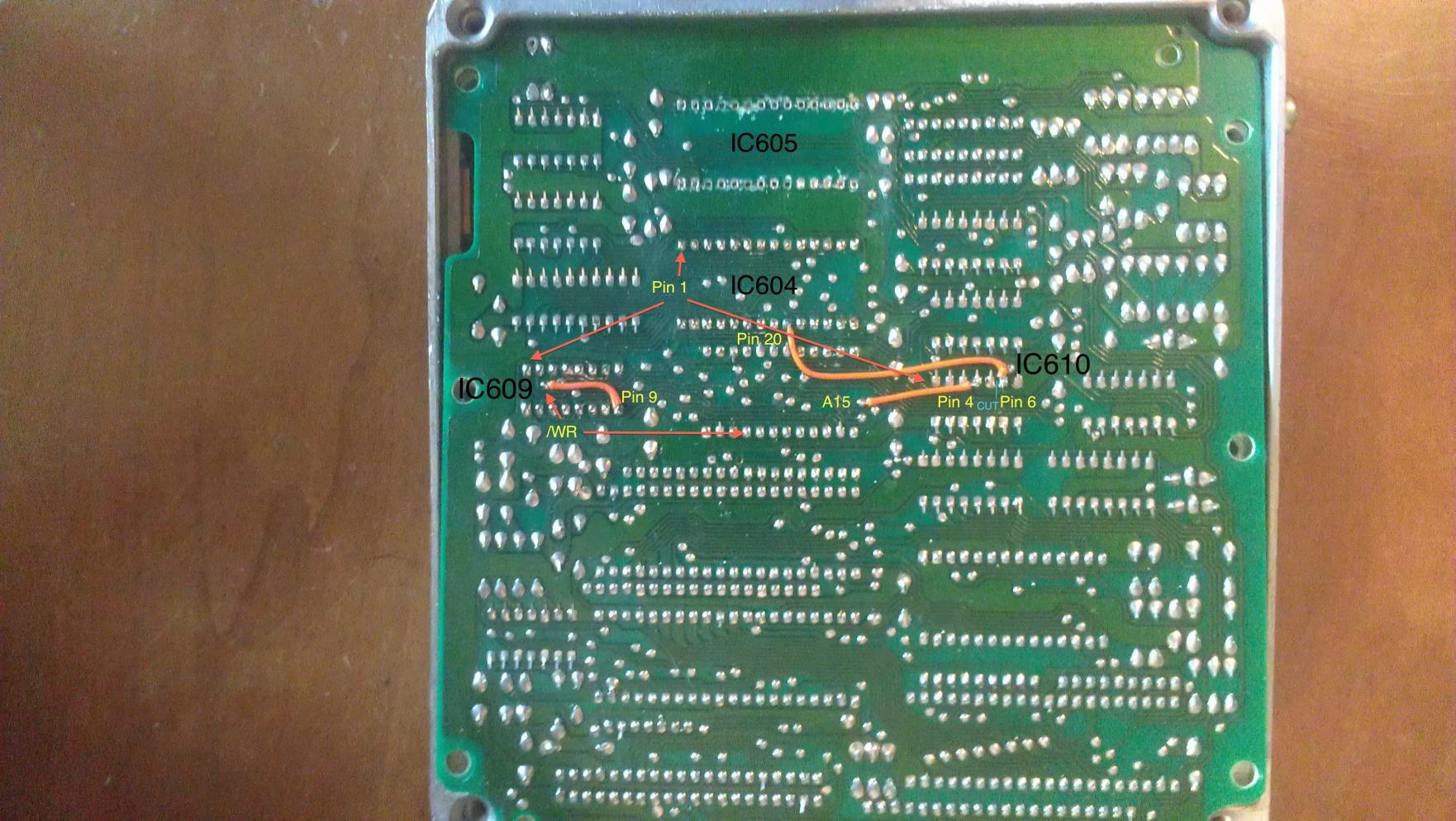
I don't yet have the RESET wired in, as I'm trying to find a more convenient location on the board for it. Next will be building the daughterboard itself, and of course, writing the communication routine.
N326 (0275/0285)
N326 (0276/0286)
N332 (0375/0385)
N333 (0376/0386)
N374 (1064)
Now, onto prepping the ECU. I'm working with an N333 ECU -- others are slightly different as to the location of certain pads on the board, but they're in the same general area.
This is what you'll be starting with. Simply desolder each of the labeled chips from the board.
BE CAREFUL WITH YOUR DESOLDERING!
It is very easy to mess up the board and sockets if you are not careful, as you can see on this board (the offender shall go unnamed...
)Afterwards, install sockets in the location of IC604 and IC609. I used Digikey part # DILB28P-223TLF and ED3046-5-ND.
Next, we need to solder on some jumper wires to gain access to certain functions of the CPU (such as /WR, A15 address chip enable to support the larger rom, and RESET). There is also one location where you will need to cut the trace on the PCB board with a razor blade/sharp knife. This won't hurt the ECU if you decide to go back, as these pins are otherwise unused. This image explains the location of the wires and their corresponding functions (in the case of /WR, you can also verify the correct pin by checking continuity to pin 21 of the SRAM module).
I don't yet have the RESET wired in, as I'm trying to find a more convenient location on the board for it. Next will be building the daughterboard itself, and of course, writing the communication routine.
Last edited by SonicRaT; Jun 20, 2014 at 01:25 PM. Reason: Edit to fix Aron's name
reminds me of overclocking a sega genisis CPU from 7 to 11 mhz for a bump in game play speed. keep up the cool work.
as far as i can see, this will be a mod yourself and tune yourself kind of affair, you're not gonna be making kits and selling anything like this guy thinks ^
as far as i can see, this will be a mod yourself and tune yourself kind of affair, you're not gonna be making kits and selling anything like this guy thinks ^
Thread Starter
Joined: Dec 2001
Posts: 10,630
Likes: 3
From: NY, MA, MI, OR, TX, and now LA or AZ!
Pretty much you'll be able to do everything/build it yourself. I may be able to toss together a kit/presoldered boards and such if people are interested in them to save themselves the time.
the physical part of it all looks fun, the soldering and running wires... but tuning it.. i assume will be in some sort of code, when you start talking uart addressing cashed stuff, you might as well say potato salad. do you have a compiler that translates the ecu's language?
in any case i think you'll agree the falls under more NEAT then practical...?
in any case i think you'll agree the falls under more NEAT then practical...?
Thread Starter
Joined: Dec 2001
Posts: 10,630
Likes: 3
From: NY, MA, MI, OR, TX, and now LA or AZ!
the physical part of it all looks fun, the soldering and running wires... but tuning it.. i assume will be in some sort of code, when you start talking uart addressing cashed stuff, you might as well say potato salad. do you have a compiler that translates the ecu's language?
in any case i think you'll agree the falls under more NEAT then practical...?
in any case i think you'll agree the falls under more NEAT then practical...?
Currently I don't use a compiler, I just write everything out by op-code (since I'm writing in assembly anyway, it's not that big of a deal).
For most people, you really won't need to bother with the code at all unless you want to add in features that haven't currently been added.
Basically, the process will go like this for your typical end-user:
- Buy/Build Board
- Program EPROM/NVSRAM with corresponding modified ROM image (I'll make these available)
- Tune via PC
Thread Starter
Joined: Dec 2001
Posts: 10,630
Likes: 3
From: NY, MA, MI, OR, TX, and now LA or AZ!
The hardware portion is now complete -- everything works as expected. I've got the communications running at 115200bps 8-N-1, and use the built in FIFO buffers to minimize CPU blocking as much as possible. Ideally, I'll be limiting the communication routines to not exceed the buffer space to avoid "hiccups" caused by updating while the car is running. Using something like the 16750 UART would help with this as well given the much larger buffer space, but this issue could be minimized by the software to avoid doing large reads/writes.
I'll be updating the schematic and designing a finalized circuit board that can be sent to the fabhouse in the near future.
Next up -- finalizing the serial communication routines for basic tasks (ECU ID, read, write, adding checksums, etc). Then, writing a program to communicate with the ECU. After that, it'll be just a matter of adding in features to the ECU code/computer program as needed.
Prototyping the whole thing..... (Ignore the crappy radioshack breadboard... my good ones are all stuffed away in storage somewhere )
)
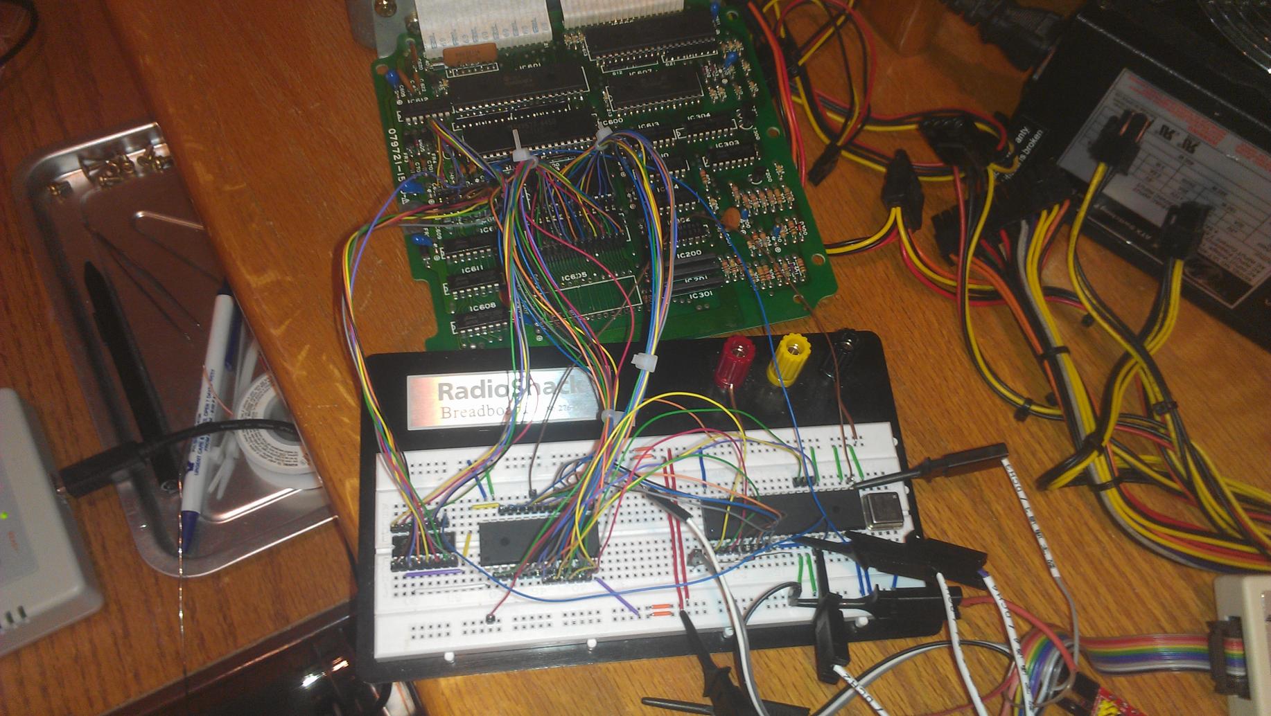
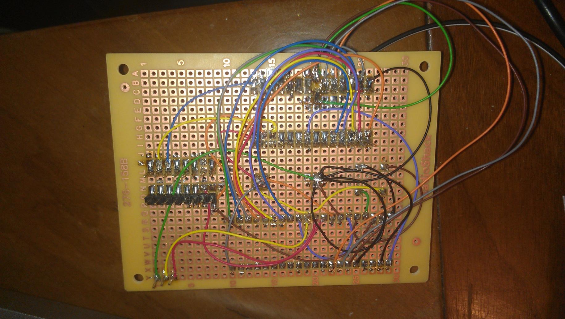
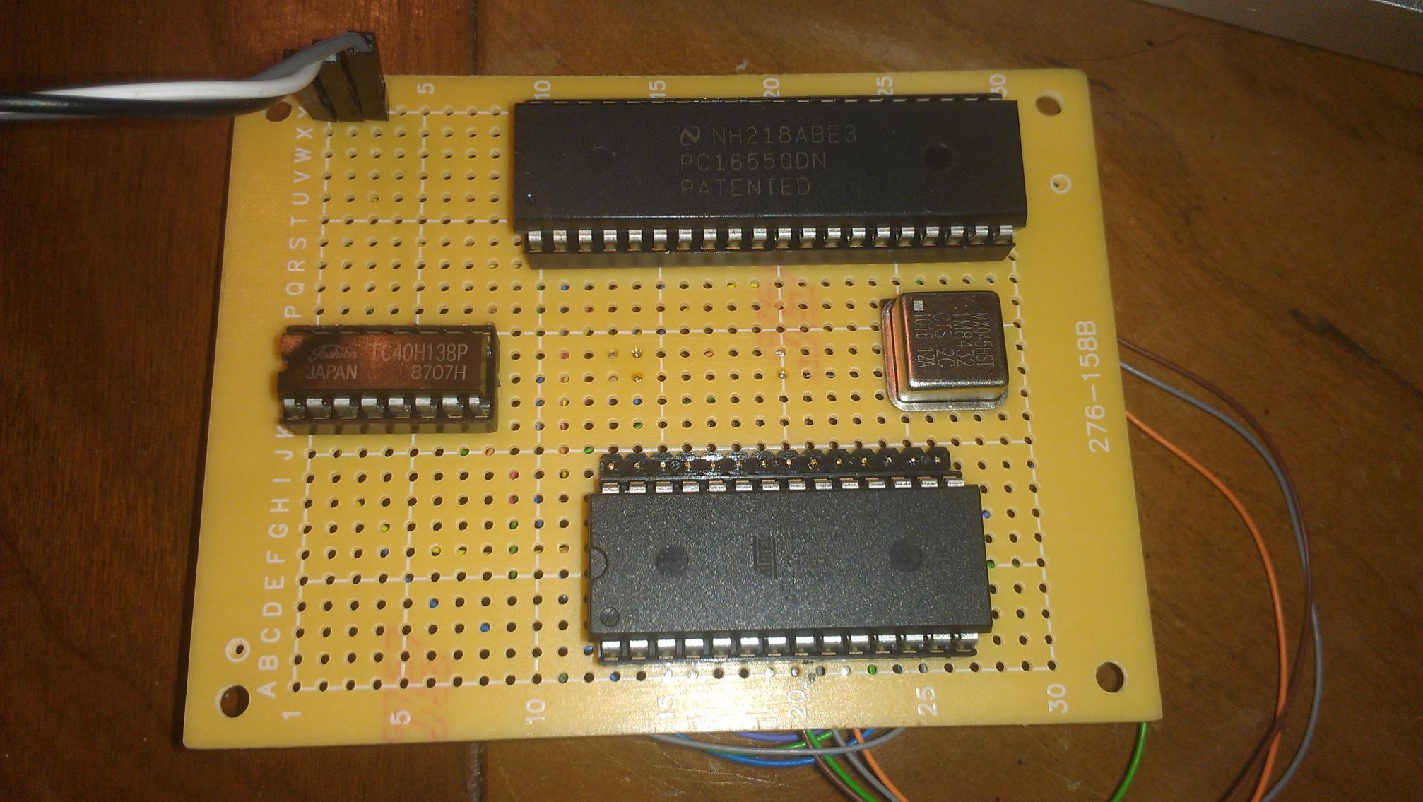
Testing it out on a board.....
I'll be updating the schematic and designing a finalized circuit board that can be sent to the fabhouse in the near future.
Next up -- finalizing the serial communication routines for basic tasks (ECU ID, read, write, adding checksums, etc). Then, writing a program to communicate with the ECU. After that, it'll be just a matter of adding in features to the ECU code/computer program as needed.
Prototyping the whole thing..... (Ignore the crappy radioshack breadboard... my good ones are all stuffed away in storage somewhere
)Testing it out on a board.....
Thread Starter
Joined: Dec 2001
Posts: 10,630
Likes: 3
From: NY, MA, MI, OR, TX, and now LA or AZ!
I would make something like that controlled by the software -- much like the PowerFC lets you disable/enable certain features.
Joined: Sep 2005
Posts: 25,581
Likes: 136
From: Smiths Falls.(near Ottawa!.Mapquest IT!)
Hurry and get this done..
I want my Robot Hooker to be ambidextrous.
By the way if anyone thinks this stuff is easy..it's NOT!.
you need freakin Super-Vision to see the crap on that board!
(pays to have tools and a nice magnifier...That crap board was MY attempt at an Rtek Chip!)
I want my Robot Hooker to be ambidextrous.
By the way if anyone thinks this stuff is easy..it's NOT!.
you need freakin Super-Vision to see the crap on that board!
(pays to have tools and a nice magnifier...That crap board was MY attempt at an Rtek Chip!)
Thread Starter
Joined: Dec 2001
Posts: 10,630
Likes: 3
From: NY, MA, MI, OR, TX, and now LA or AZ!
Hurry and get this done..
I want my Robot Hooker to be ambidextrous.
By the way if anyone thinks this stuff is easy..it's NOT!.
you need freakin Super-Vision to see the crap on that board!
(pays to have tools and a nice magnifier...That crap board was MY attempt at an Rtek Chip!)
I want my Robot Hooker to be ambidextrous.
By the way if anyone thinks this stuff is easy..it's NOT!.
you need freakin Super-Vision to see the crap on that board!
(pays to have tools and a nice magnifier...That crap board was MY attempt at an Rtek Chip!)
I find I tend to do worse when I have the magnifying glass... Even when soldering 0603 SMD by hand, I'd still rather do it without the magnifying glass.
MECP Certified Installer
Joined: Feb 2009
Posts: 3,176
Likes: 3
From: Mesquite, TX-DFW
Tuning it will be done via a computer program -- the same as any other aftermarket ECU out there. I'll be writing this program and sticking it on google code (ie, open-source) so that anyone can update it, add features, whatever. Think RTEK, except with a computer instead of a palm-pilot.
Currently I don't use a compiler, I just write everything out by op-code (since I'm writing in assembly anyway, it's not that big of a deal).
For most people, you really won't need to bother with the code at all unless you want to add in features that haven't currently been added.
Basically, the process will go like this for your typical end-user:
- Buy/Build Board
- Program EPROM/NVSRAM with corresponding modified ROM image (I'll make these available)
- Tune via PC


This is making me reconsider getting another megasquirt for my upcoming project. I ALMOST want to stick with the factory stuff now... Would there be a way to re-program the ECU enough that a N/A ECU could safely be used with a T2 car? Or finding a non-flapper door MAF (thermistor?) that we can make flow more? What I'm getting at is trying to remove the proprietary portion of the factory sensors and replace with more common oem or aftermarket options.
Is there anyway to poke into the ECU and see what coolant and air temperatures its receiving from the sensors? I'm thinking make it "standalone-ish" and have the tuning software display relative temperatures.
Loving the quick progress here! Keep up the great work. I wish I could be of more assistance.
Thread Starter
Joined: Dec 2001
Posts: 10,630
Likes: 3
From: NY, MA, MI, OR, TX, and now LA or AZ!
This is making me reconsider getting another megasquirt for my upcoming project. I ALMOST want to stick with the factory stuff now... Would there be a way to re-program the ECU enough that a N/A ECU could safely be used with a T2 car? Or finding a non-flapper door MAF (thermistor?) that we can make flow more? What I'm getting at is trying to remove the proprietary portion of the factory sensors and replace with more common oem or aftermarket options.
Is there anyway to poke into the ECU and see what coolant and air temperatures its receiving from the sensors? I'm thinking make it "standalone-ish" and have the tuning software display relative temperatures.
Loving the quick progress here! Keep up the great work. I wish I could be of more assistance.
Is there anyway to poke into the ECU and see what coolant and air temperatures its receiving from the sensors? I'm thinking make it "standalone-ish" and have the tuning software display relative temperatures.
Loving the quick progress here! Keep up the great work. I wish I could be of more assistance.
I have just about every sensor mapped out and converted to readable values -- that's part of what I've been doing the past couple of days. I'm working on the interface software that'll run on the PC which will support datalogging and tuning.
The "hardware" is pretty much done.... I just need to test the PCB's from the fab house to make sure everything is in order there. The communication routine is finished -- it's just a matter of adding in specific commands for each particular feature (such as timing maps, checking sensors, checking switches, error codes, fuel maps, etc). Currently I'm using a "developer" command that'll let me read/write anywhere in the ECU. This will be disabled later as there will be no purpose for direct access anymore.

Senior Member
Joined: Apr 2009
Posts: 311
Likes: 2
From: Lynchburg, VA
I too would be interested in removing the vane air flow meter to switch to something more practical. Even if thats not an option in early development that wouldn't bother me a bit. Now, how expandable will the program be? Just stock parameters or can things like external inputs be added like a clutch switch signal to control a launch control/two step. Example would be like hondata that updates software/firmware periodically to address bugs and add features. This might be alot to ask for for such an older board to start with.
I know those are big questions to ask right now, but in the end it wouldnt mater. A way to be able to datalog and adjust without breaking the bank for something like the power fc and commander is wonderful.
I know those are big questions to ask right now, but in the end it wouldnt mater. A way to be able to datalog and adjust without breaking the bank for something like the power fc and commander is wonderful.
Thread Starter
Joined: Dec 2001
Posts: 10,630
Likes: 3
From: NY, MA, MI, OR, TX, and now LA or AZ!
I too would be interested in removing the vane air flow meter to switch to something more practical. Even if thats not an option in early development that wouldn't bother me a bit. Now, how expandable will the program be? Just stock parameters or can things like external inputs be added like a clutch switch signal to control a launch control/two step. Example would be like hondata that updates software/firmware periodically to address bugs and add features. This might be alot to ask for for such an older board to start with.
I know those are big questions to ask right now, but in the end it wouldnt mater. A way to be able to datalog and adjust without breaking the bank for something like the power fc and commander is wonderful.
I know those are big questions to ask right now, but in the end it wouldnt mater. A way to be able to datalog and adjust without breaking the bank for something like the power fc and commander is wonderful.
You make it sound so easy.
I'm really excited to see this in a working car. This could be the next "big thing" for the FC that helps bridge the gap between going rtek and going standalone.
I'm really excited to see this in a working car. This could be the next "big thing" for the FC that helps bridge the gap between going rtek and going standalone.
Senior Member
Joined: Apr 2009
Posts: 311
Likes: 2
From: Lynchburg, VA
Think about it, what he is building is standalone using whats already given to us. The honda crowd has been doing this for years....
Keep up the good work, I did not realise the ecu had a clutch pedal signal. The more you learn, the more you know.
Keep up the good work, I did not realise the ecu had a clutch pedal signal. The more you learn, the more you know.

Thread Starter
Joined: Dec 2001
Posts: 10,630
Likes: 3
From: NY, MA, MI, OR, TX, and now LA or AZ!
Amusingly, I'm finding the most difficult part of this entire task is application design.... I can't decide on a UI for the interface software at all. I'm terrible at creating interfaces.
Getting this software done and waiting for boards to show up is pretty much the hold up at the moment....
Oh, and I've also made a schematic that supports bluetooth too.
Getting this software done and waiting for boards to show up is pretty much the hold up at the moment....
Oh, and I've also made a schematic that supports bluetooth too.
Thread Starter
Joined: Dec 2001
Posts: 10,630
Likes: 3
From: NY, MA, MI, OR, TX, and now LA or AZ!
I decided to not reinvent the wheel, so I basically cloned my OSX PowerFC application (FC-X, which is still sitting on the backburner waiting to be finished).
You'll be greeted with this dashboard upon launch, that will display in real-time when "connected" the ECU. I'll stick in a section that includes all the other important values (TPS, AFM, ignition advance, injector pulsewidths, etc), once I can figure out a good way of putting that information on screen.
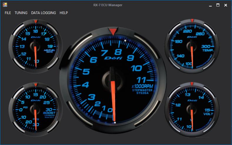
I have a few of the other basic screens started, but they're not very presentable.
NOTE: I absolutely will not be creating a datalog viewer with this app. I think there's absolutely no need for me to waste my time on this when the extremely awesome MegaLogViewer is available for free and will support the output from this application. I will have some basic necessities, such as Map Watch, and monitoring all of the sensors/error codes/etc, but the datalogging will consist of simply recording to a CSV file compatible with MegaLogViewer.
You'll be greeted with this dashboard upon launch, that will display in real-time when "connected" the ECU. I'll stick in a section that includes all the other important values (TPS, AFM, ignition advance, injector pulsewidths, etc), once I can figure out a good way of putting that information on screen.
I have a few of the other basic screens started, but they're not very presentable.
NOTE: I absolutely will not be creating a datalog viewer with this app. I think there's absolutely no need for me to waste my time on this when the extremely awesome MegaLogViewer is available for free and will support the output from this application. I will have some basic necessities, such as Map Watch, and monitoring all of the sensors/error codes/etc, but the datalogging will consist of simply recording to a CSV file compatible with MegaLogViewer.
That makes sense.
I'm sure you've thought of this already and it's not possible, but i'll say it anyway. I assume its too difficult to interface or interpret the ECU I/O to work with tuner studio?
I'm sure you've thought of this already and it's not possible, but i'll say it anyway. I assume its too difficult to interface or interpret the ECU I/O to work with tuner studio?