
Stock ECU Real-Time Tuning / Datalogging

i have an 88 turbo that has an rTek i would be willing to re do the wiring go to the S5 Turbo ECU which i have... i think a chipped version( like knightports?). the motor needs to come out and be refreshed, may have a cracked apex seal but w/e.
i would totally wiring up a modded fc ECU to use in the rx8 for a turbo setup.. also i have an FB that was carb'd pretty much empty canvas at this point.
so you yell me how you want it, i think the na s4 is the least needed? s5 n/a would be nice, and i would do either series of turbo.


Joined: Mar 2001
Posts: 31,857
Likes: 3,243
From: https://www2.mazda.com/en/100th/
here is the AFM info; https://www.rx7club.com/2nd-generati...mo-afm-961741/
Thread Starter
Joined: Dec 2001
Posts: 10,630
Likes: 3
From: NY, MA, MI, OR, TX, and now LA or AZ!
here is the AFM info; https://www.rx7club.com/2nd-generati...mo-afm-961741/

Senior Member
Joined: Apr 2009
Posts: 311
Likes: 2
From: Lynchburg, VA
Just got out of work, didnt get a chance to do any voltage readings vs temps, though it seems we have gotten afm readings, thats a step in the right direction. I will get on the temp readings tomorrow and see what all I can get you.
I forgot I didn't have a 12V power source at home, but If I have some time at work tomorrow I'll bring in my setup and try for some measurements.
I did however get values for the IAT Resistance vs. Temp. (Yes I know you asked for voltage)
I thought I could extract it out, but without a reference current it's useless. Do you know what the ECU uses for current on that wire? I'm guessing about 1 milliamp.
My experiment, that I'll repeat tomorrow:

Water covered only the sensor, starting with a high temperature and lowering progressively.
I used a cheap meat thermometer to verify temp and a Bluepoint EEDM5035 to collect values.
Temp (F) Res (kOhm)
87 23.6
90 21.9
96 18.6
100 16.8
104 14.8
107 13.4
115 12.3
120 10.9
125 9.9
130 8.8
135 7.9
140 6.9
145 6.3
150 5.4
157 4.8

Also from the FSM:
The IAT in the MAF:

I did however get values for the IAT Resistance vs. Temp. (Yes I know you asked for voltage)
I thought I could extract it out, but without a reference current it's useless. Do you know what the ECU uses for current on that wire? I'm guessing about 1 milliamp.
My experiment, that I'll repeat tomorrow:
Water covered only the sensor, starting with a high temperature and lowering progressively.
I used a cheap meat thermometer to verify temp and a Bluepoint EEDM5035 to collect values.
Temp (F) Res (kOhm)
87 23.6
90 21.9
96 18.6
100 16.8
104 14.8
107 13.4
115 12.3
120 10.9
125 9.9
130 8.8
135 7.9
140 6.9
145 6.3
150 5.4
157 4.8
Also from the FSM:
The IAT in the MAF:
Thread Starter
Joined: Dec 2001
Posts: 10,630
Likes: 3
From: NY, MA, MI, OR, TX, and now LA or AZ!
I'm not quite sure. Although, I may be able to figure that out by working backwards. The ECU defaults to a specific ADC value which corresponds to given values they reference in the FSM. Using the FSM, I would have a resistance reference to a set voltage, so I should be able to work backwards to obtain current.
Thread Starter
Joined: Dec 2001
Posts: 10,630
Likes: 3
From: NY, MA, MI, OR, TX, and now LA or AZ!
With the above information, I've worked out some generic linear conversions that match up fairly well to the FSM findings. These should likely be sufficient enough.
(Vref - WTS or AFMAIT) * (160/Vref) - 60 = Temp*C
(Vref - AIT) * (125/Vref) = Temp*C
Example:
(5.0v - 2.38v) * (155/5.0v) - 60 = ~21.2*C (FSM indicates this voltage should be 20*C)
(5.0v - 0.5v) * (155/5.0v) - 60 = ~79.5*C (FSM indicates this voltage should be 80*C)
Using the actual ADC value from the ECU:
(255 - 122) * (155/256) - 60 = ~20.5*C
(255 - 27) * (155/256) - 60 = ~78*C
Senior Member
Joined: Apr 2009
Posts: 311
Likes: 2
From: Lynchburg, VA
Seems we got most of the information. Some math should give us the range. Going off alldata at -4*f we should see a resistance of 16.2k .003a draw...68*f we should see a resistance reading of 2.45k should be .002a draw 104*f 1100ohms .004a :140*f 550ohms .009a and at 176*F 320 ohms should be a .015A draw on the circuit. Havent had time to verify this yet and alldata has been known to be wrong on its values in the past.
Joined: Mar 2001
Posts: 31,857
Likes: 3,243
From: https://www2.mazda.com/en/100th/
here are some of the sensor graphs. notice please that the Japanese manual has theses and the US manual does not.
the air temp sensor is S4, S5 and Cosmo, same part number. the FD has a different part, so they could get it to break all the time, and its curve is reversed.
the water temp sensor is the same S3, S4, S5, Cosmo. FD is different, but the sensor curve is the same. the newer one is actually smaller to clear the alternator!
the MAP is for a T2, and Cosmo, its just a 2 bar sensor, the FD uses a 2.25 bar sensor, or thereabouts.
and last is the S5, Cosmo, and FD TPS curve. the S4 would use just the narrow range part
Thread Starter
Joined: Dec 2001
Posts: 10,630
Likes: 3
From: NY, MA, MI, OR, TX, and now LA or AZ!
Cool. Think we're set to go on the sensor data now.
I've been working on the fuel correction. Currently, I'm performing fuel corrections almost entirely in the same manner as an S-AFC. Basically, I apply the correction to the AFM value. From here, the ECU does the rest of its corrections/additions to this base value. As a result, this allows me to do a swing of -100% to +100% while maintaing the stock ECU injector controls -- ie, max duty cycle, etc. I can perhaps allow the max duty cycle to be a hair higher to accommodate more control.
In other news, I have successfully tested one of two methods for ditching the AFM. This first method is extremely easy -- basically all I do is mimic the AFM values using a RPM/MAP based lookup table. This gives you 1024 steps of resolution to control the fuel values in a 20x20 table.
The second method will be a lookup table that actually contains the base injector timing (ms) map. This will take a little longer, as I'll need to adapt the various corrections to work on this value.

Senior Member
Joined: Apr 2009
Posts: 311
Likes: 2
From: Lynchburg, VA
Cool. Think we're set to go on the sensor data now.
I've been working on the fuel correction. Currently, I'm performing fuel corrections almost entirely in the same manner as an S-AFC. Basically, I apply the correction to the AFM value. From here, the ECU does the rest of its corrections/additions to this base value. As a result, this allows me to do a swing of -100% to +100% while maintaing the stock ECU injector controls -- ie, max duty cycle, etc. I can perhaps allow the max duty cycle to be a hair higher to accommodate more control.
In other news, I have successfully tested one of two methods for ditching the AFM. This first method is extrem the ely easy -- basically all I do is mimic AFM values using a RPM/MAP based lookup table. This gives you 1024 steps of resolution to control the fuel values in a 20x20 table.
The second method will be a lookup table that actually contains the base injector timing (ms) map. This will take a little longer, as I'll need to adapt the various corrections to work on this value.
Thread Starter
Joined: Dec 2001
Posts: 10,630
Likes: 3
From: NY, MA, MI, OR, TX, and now LA or AZ!
I'm not exactly sure what you're stating -- but yes, I should be able to make it work with a larger MAP sensor.
I also had one more question comparing your set up to existing units out there (Rtek). I currently am utilizing the Variable Resistor as an input, because pocket logger has internalized the settings into the software. Would you be doing something along these lines at all to create optional logable/ scaleable inputs with otherwise "open" pins on the ECU.
I only ask because I will need to disable this if you don't offer this. I am using this channel to log my AFR's from a wideband.
I only ask because I will need to disable this if you don't offer this. I am using this channel to log my AFR's from a wideband.
Thread Starter
Joined: Dec 2001
Posts: 10,630
Likes: 3
From: NY, MA, MI, OR, TX, and now LA or AZ!
I also had one more question comparing your set up to existing units out there (Rtek). I currently am utilizing the Variable Resistor as an input, because pocket logger has internalized the settings into the software. Would you be doing something along these lines at all to create optional logable/ scaleable inputs with otherwise "open" pins on the ECU.
I only ask because I will need to disable this if you don't offer this. I am using this channel to log my AFR's from a wideband.
I only ask because I will need to disable this if you don't offer this. I am using this channel to log my AFR's from a wideband.
Trunks are for corpses.
Joined: Nov 2003
Posts: 189
Likes: 0
From: St.Pete FL
I've got a spare S4 N/A ECU and a daily driver car I could possibly test this on. 
Did you ever post any of this someplace public like Google Code or Github? I wanted to build a desktop PC application and LED dashboard readout for my Rtek 2.0 but only got so far reverse engineering their serial protocol so this project is really interesting to me.
Did you ever post any of this someplace public like Google Code or Github? I wanted to build a desktop PC application and LED dashboard readout for my Rtek 2.0 but only got so far reverse engineering their serial protocol so this project is really interesting to me.
Thread Starter
Joined: Dec 2001
Posts: 10,630
Likes: 3
From: NY, MA, MI, OR, TX, and now LA or AZ!
I've got a spare S4 N/A ECU and a daily driver car I could possibly test this on.
Did you ever post any of this someplace public like Google Code or Github? I wanted to build a desktop PC application and LED dashboard readout for my Rtek 2.0 but only got so far reverse engineering their serial protocol so this project is really interesting to me.
Did you ever post any of this someplace public like Google Code or Github? I wanted to build a desktop PC application and LED dashboard readout for my Rtek 2.0 but only got so far reverse engineering their serial protocol so this project is really interesting to me.
Thread Starter
Joined: Dec 2001
Posts: 10,630
Likes: 3
From: NY, MA, MI, OR, TX, and now LA or AZ!
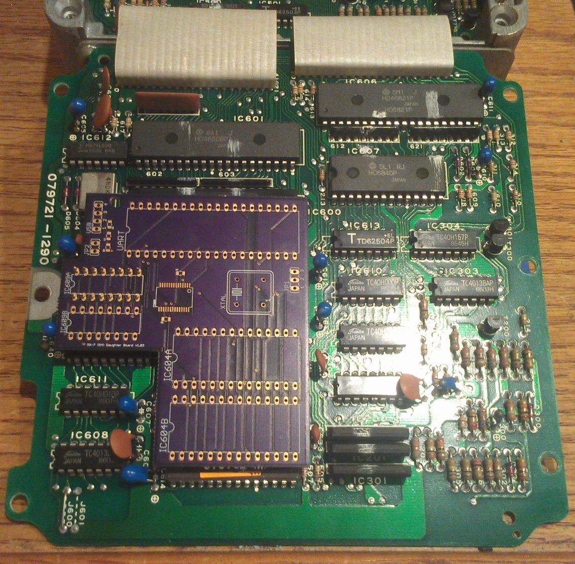
First batch of boards are finally here. There were a couple of minor issues with this board revision that have been fixed for the next set. Another order of parts should be here tomorrow from digikey that'll let me finalize everything to get these things ready to go on test vehicles.
Man, wish I'd seen this earlier. I can donate two S5 Turbo ECU's that I won't be needing, I'll even pay the shipping one way cheap/slow. One is marked N374 (Japanese market), the other came with a JDM motor but the sticker's boogered up, can't read it. PM if interested.
I would like to be able to real time tune an S4 T2 with the separate knock control box. Also, is there any way you could find the sensor data for the knock sensor's output?
Oh, and subscribed!
I would like to be able to real time tune an S4 T2 with the separate knock control box. Also, is there any way you could find the sensor data for the knock sensor's output?
Oh, and subscribed!
Last edited by RX744CSP; Aug 10, 2014 at 01:53 PM.
Thread Starter
Joined: Dec 2001
Posts: 10,630
Likes: 3
From: NY, MA, MI, OR, TX, and now LA or AZ!
Man, wish I'd seen this earlier. I can donate two S5 Turbo ECU's that I won't be needing, I'll even pay the shipping one way cheap/slow. One is marked N374 (Japanese market), the other came with a JDM motor but the sticker's boogered up, can't read it. PM if interested.
I would like to be able to real time tune an S4 T2 with the separate knock control box. Also, is there any way you could find the sensor data for the knock sensor's output?
Oh, and subscribed!
I would like to be able to real time tune an S4 T2 with the separate knock control box. Also, is there any way you could find the sensor data for the knock sensor's output?
Oh, and subscribed!
As for the knock control -- you can find some basic information on how it works within the training manuals. I may actually see about making it configurable within the ECU to allow for more timing retard, etc.
Cool. Be happy to send them on whenever you need them, I have no plans to do anything with them.
Did that training manual with the other sensor specs have any knock sensor output information? The US market FSM just says 'can't test, replace' about the sensor itself, says to tap on the rotor housing with a screwdriver etc and watch for timing retard.
Did that training manual with the other sensor specs have any knock sensor output information? The US market FSM just says 'can't test, replace' about the sensor itself, says to tap on the rotor housing with a screwdriver etc and watch for timing retard.