
Stock ECU Real-Time Tuning / Datalogging

Thread Starter
Joined: Dec 2001
Posts: 10,630
Likes: 3
From: NY, MA, MI, OR, TX, and now LA or AZ!
Stock ECU Real-Time Tuning / Datalogging
There are a host of other cars from similar generations with open communities revolving around tuning the stock ECU's and modifying them to support real-time tuning and datalogging features.
I have spent a considerable time working on this on a spare FD ECU I have laying around, and decided to start with the much easier S4 ECU first and work myself forward. This thread will more or less chronicle my findings, schematics, and progress in hopes of sparking a similar community of open development towards cheaper tuning alternatives.
To begin, credit needs to be given to those who have come before and made this task a whole lot easier.
Credits
ROM Boards for 3S-GTE & 3VZ-FE ECUs
3P's TCCS Disassembly/Analysis
Rx-7 Series IV & V ECU Reverse Engineering
And countless other resources that I've surely forgotten amid the reading....
Now, onto the actual task at hand....
Background Information
The S4 ECU runs from a MC6303/HD6303 variant processor, utilizing two 64kbit EPROM's by which it runs from. These EPROM's are loaded into memory address space 0xC000-0xFFFF. (The S5 appears to be 0x8000-0xFFFF).
While hardware specifications suggest that the 6303 has serial communications (SCI) capabilities, at best looking at specs the highest possible baud rate would be roughly 38,400bps. Since these serial requests would be blocking, it's probable that these requests would be a detriment to overall CPU performance. However, this could be done if the hardware is available by simply injecting the necessary code bits into the stock ROM and utilizing the SCI interrupt to handle read events. This would require less overall hardware modification.
Alternatively, and the route I'm pursuing myself, is to add a UART that can be addressed directly on the address bus. There appear to be a number of ranges readily available through IC609 -- 0x5000-0x7000 in 1K blocks. For now, I'll be assigning it to 0x5000 and any reference to such will refer to the UART. Doing this, we can clock the UART externally up its maximum specification, and either use an interrupt driven read/write routine, or a less invasive polling routine and use the built-in FIFO of the UART to handle queuing.
The Problem
Of course, the stock EPROM can only be erased/programmed using UV-light. This means, to enable editing/writing, it needs to be replaced. Again, this is where multiple options come into play. The stock EPROM can be replaced with an EEPROM such as the AT28C256, which can be electronically reprogrammed. However, the write routines are still quite slow, albeit much faster than previously. This means that any write to the EEPROM could potentially block the processor until the write routine is complete. According to the datasheets, this could be as little as a 3-10ms. However, in the world of your engine, that could be a long time. Alternatively, it's possible to replace the stock EPROM with an NVSRAM module. These are typically battery backed up RAM that perform a "write" routine whenever they detect power failing -- which gives much better read/write speeds.
The second problem is that the stock EPROM uses almost its entire available memory space for the stock programming. Adding in communication routines would be rather difficult unless they were extremely efficient. To resolve this, we can allocate an additional 1K to an additional EEPROM using IC609. If more space than this is needed, IC609 does have an additional 1K available, but additional logic circuits would be needed to allocate the contiguous 2K rather than single 1K chunks.
Building it in theory
Ideally, you'll want to socket IC609 and IC604 (remove IC605). Then, build a board that lifts both of those (IC609 and IC604). From there, wire IC609-10 (0x5000) to the CE pin on the UART, and IC609-9 (0x6000) to the CE pin on the serial communications EEPROM. Connect VCC/GND/Data bus/Address bus accordingly. Typically, it appears that the RD pin on the stock EPROM is connected to nothing and left high on its own, since the EPROM is never "written" to. Consequently, we need to bring the /RD signal from the ECU to the board, so we can tell the EEPROM's and the UART when we want to read, and additionally, when we want to write. The CPU appears to share a line for both R/W, so this could either be branched depending upon the logic at this pin, or we can pick up the signals from IC612 if need be.
Programming it in theory
Perhaps the hardest part of the whole thing -- splicing the communications routine into the stock ECU. There are a number of different ways of doing this -- depending upon if you prefer to use an interrupt driven communications protocol or a polling method. You can simple write the communications routine in the second EEPROM, and then throw in it's entry point (relative to 0x6xxx) in the vector table found at the end of the primary EEPROM (0xFFDE-0xFFFF). Or, perhaps a less intrusive method, would be to use polling. In this way, you will locate a primary loop in the stock programming, and inject a call to the communications routine. The communications routine will check the UART registers (available at 0x5000), and perform actions based upon the result -- either read a memory address (for things such as live datalogging, looking at the current timing maps, or whatever else), or write in new values based upon changes sent in.
This leads to another question -- where are the values we need to change? While this may seem difficult at first, it's actually not all that hard to do. I've built an EPROM tracing devices that attaches to the address bus of the EPROM. Whenever the ECU access the EPROM, a program automatically interprets the address on the address bus and overlays this address ontop of an EPROM dump. As a result, I can see where in memory the ECU is accessing in real-time. From here, I simply change the value of a sensor -- such as the TPS or the water temp sensor, and I can see exactly where in memory the program is changing based upon those results. This allows me to track down where correction tables are and a whole host of other things.
Future
Obviously, there's a lot more to be done -- such as getting the communications program written and available, putting together an actual schematic, writing software that can interpret the ram/communicate with the ECU once the task is done. However, I wanted to start the dialog on getting this all moving forward.
Additionally, I have a serious lack of ECU's available to test/debug/build with. If anyone wants to donate an ECU towards the cause or borrow one out, it'll go a long way toward seeing this progress. I'll get some schematics up here shortly that'll better explain how this will work out.
Joined: Sep 2005
Posts: 25,581
Likes: 136
From: Smiths Falls.(near Ottawa!.Mapquest IT!)
I have a N333(0r 2) that I tried to de-chip for an Rtek 1.8 But gave up on and never pulled the stock chip.
It would have to be examined and probably resoldered to make sure the contacts are good.
If you want it,pay shipping and it's yours.
It would have to be examined and probably resoldered to make sure the contacts are good.
If you want it,pay shipping and it's yours.
Thread Starter
Joined: Dec 2001
Posts: 10,630
Likes: 3
From: NY, MA, MI, OR, TX, and now LA or AZ!
That'd be perfect, worse comes to worse I can just run some jumper wires to patch things up if the contacts in the socket are messed up. Shoot me a PM with details. Once this order from digikey gets here I can start working on the serial comms programming, which is really the hardest part of the whole thing. I don't have the S4 TII ROM yet either, so that'll help cover all the bases for the S4 ECU's.
Thread Starter
Joined: Dec 2001
Posts: 10,630
Likes: 3
From: NY, MA, MI, OR, TX, and now LA or AZ!
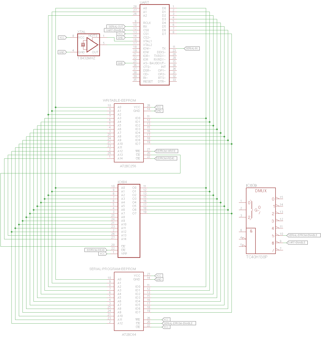
I've attached a very quick and dirty schematic that shows how everything will be connected and the the importance of IC609 for addressing the additional devices (the serial programming EPROM and the UART). This schematic is not without errors, as it doesn't have VCC/GND for a number of chips, and it obviously doesn't have a proper source for the EEPROM READ/WRITE inputs yet -- the stock ECU just left this hooked to VCC assuming the EPROM would only ever be read. This is simply a visual reference for those who wish to understand how this will work -- or wish to help out in the process and test things on their own.


Very cool. I have 2 N326 and a N327 if you would like to pay shipping for one.
How do you plan to interface this to a program that is end user friendly? I assume the serial connection would then go to a computer, do you need to write the program for windows as well?
How do you plan to interface this to a program that is end user friendly? I assume the serial connection would then go to a computer, do you need to write the program for windows as well?
Thread Starter
Joined: Dec 2001
Posts: 10,630
Likes: 3
From: NY, MA, MI, OR, TX, and now LA or AZ!
Yeah, it'll simply interface with a program via RS232. Making the interface program is perhaps the easiest part of it all. I'll probably design a schematic/board combination that uses the FTDI USB->Serial interface, as they're the most widely available and I use them for tons of other things. I'll probably make a couple of them so they're easy for people to replicate/build on their own -- as the FTDI is surface mount which can be tricky to solder for new comers.
I have the entire N327 ROM disassembled and large portions of it mapped out already, but I don't have a corresponding ECU to go along with it. PM what it'd cost to ship it to Lansing, MI area. That should just about cover me on S4 ECU's.
I have the entire N327 ROM disassembled and large portions of it mapped out already, but I don't have a corresponding ECU to go along with it. PM what it'd cost to ship it to Lansing, MI area. That should just about cover me on S4 ECU's.
Trending Topics

Joined: Mar 2001
Posts: 31,835
Likes: 3,233
From: https://www2.mazda.com/en/100th/
neat project! i've been wanting to do something like this forever, but seem to lack the skill/relevant knowledge
if i may make a suggestion; real time tuning isn't critical. if you're just making tweaks, its fine to reflash the chip, imo.
if i may make a suggestion; real time tuning isn't critical. if you're just making tweaks, its fine to reflash the chip, imo.
Thread Starter
Joined: Dec 2001
Posts: 10,630
Likes: 3
From: NY, MA, MI, OR, TX, and now LA or AZ!
Reflashing the chip takes a lot of time, as far as removing the ROM/reflashing/sticking it back in... and you still lack the datalogging ability. Once you add the logging ability, the rest pretty much comes with it.
Remember, the 90s Honda guys, GM guys, Ford guys, etc went through this years and years ago. I suggest you poke around their tuning forums and vendors like Moates (Moates Quarterhorse etc). And of course, there's the Rtek 2.1 which has already been down this road a long time ago even though updates have been minimal.
Some stock ECUs from the era (mod 80s to early-mid 90s) had EPROMs from the factory, like certain model year Eagle Talon/Eclipse. For the rest you basically need to solder in one and use a ROM burner or ROM emulator to work.
Keep in mind that when this engine was being developed they used special ECUs with a device to extend the amount of RAM space for realtime access at higher speeds. This is still used today in development. The most popular system is INCA by ETAS (a division of Bosch) and it's used by OEMs and suppliers. The newest stock ECUs have 10 megabytes of flash memory just for the gazillions of stock software and calibrations inside.
Thread Starter
Joined: Dec 2001
Posts: 10,630
Likes: 3
From: NY, MA, MI, OR, TX, and now LA or AZ!
Remember, the 90s Honda guys, GM guys, Ford guys, etc went through this years and years ago. I suggest you poke around their tuning forums and vendors like Moates (Moates Quarterhorse etc). And of course, there's the Rtek 2.1 which has already been down this road a long time ago even though updates have been minimal.
Keep in mind that when this engine was being developed they used special ECUs with a device to extend the amount of RAM space for realtime access at higher speeds. This is still used today in development. The most popular system is INCA by ETAS (a division of Bosch) and it's used by OEMs and suppliers. The newest stock ECUs have 10 megabytes of flash memory just for the gazillions of stock software and calibrations inside.
Speaking of, I have the N374 S5 TII timing maps if you're interested in updating your incredibly informative timing threads with! I'd been meaning to send that over to you.
Thread Starter
Joined: Dec 2001
Posts: 10,630
Likes: 3
From: NY, MA, MI, OR, TX, and now LA or AZ!
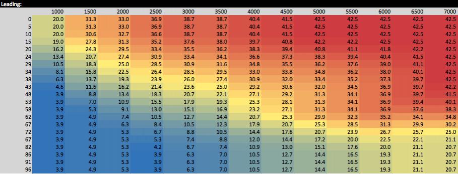
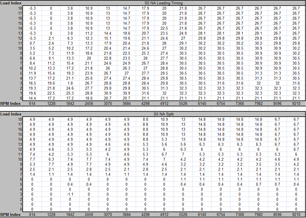
Here are the S5 N374 timing maps.... I've not verified the RPM axis is correct, it's simply what I have found others who worked on the N374 ROM have mapped them to.
Do you have the S4 and S5 na timing maps? I used to have the S5 map but don't know where it is anymore. I've moved twice since I saw it last.
What do the load values correspond to on those maps?
What do the load values correspond to on those maps?
Thread Starter
Joined: Dec 2001
Posts: 10,630
Likes: 3
From: NY, MA, MI, OR, TX, and now LA or AZ!
I have a S4 N/A ECU I could pull the map from. I don't have a S5 N/A ECU. I'll make up some charts of the S4 later today. I also got the ECU from misterstyx69, so I'll be starting on the S4 TII ECU ROM and the hardware to communicate with it.
Thread Starter
Joined: Dec 2001
Posts: 10,630
Likes: 3
From: NY, MA, MI, OR, TX, and now LA or AZ!
It will likely be a bit before I'd have time to get to the S5. If you don't mind being without it for a while, otherwise, I can just hit you up once the S4 hardware is done.
S5 NA:
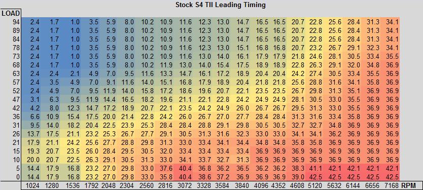
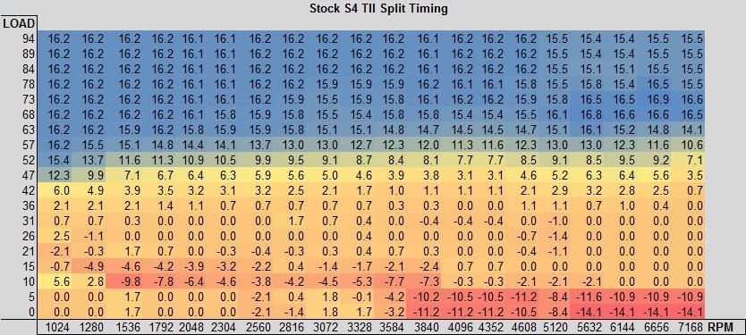
S4 T2:
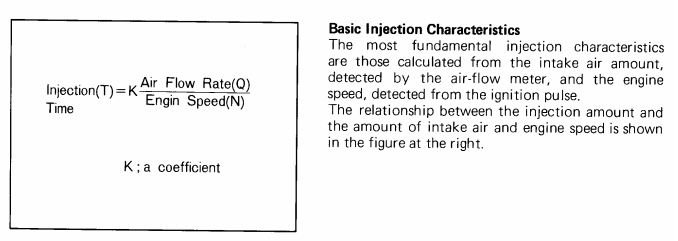
All we know about the load is that it is a term proportional to airflow/rpm , similar to most every other airflow-based engine management system.
If someone could post the S4 NA timing maps that'd be great. It's highly likely that the load scaling, in terms of what physical value each row represents, is different on every one of these engines. Usually it's:
1) some seemingly dimensionless value (early Nissan, Mitsubishi)
2) airflow per intake stroke charge (GM, Chrysler)
3) grams of air per revolution (Subaru)
4) some pumping efficiency calculation (newer Mazda like the Rx-8)
On a lot of the modern ECUs the load terms are based on airflow BUT the airflow is actually modeled even if there is a mass airflow sensor physically onboard the engine. It's hybrid of speed density and mass airflow. There isn't such a clear distinction between the two systems now, when stock tunes are doing backpressure calculations, residual gas estimation, effective compression ratio calculations, etc.
Now since this is a volume airflow meter on all these Rx-7's, the airflow unit could be some volume amount multiplied by some physical constants. Or maybe the volume is converted into a mass in the software based on lookup tables and other sensor readings. It's fair to say that the load units on the stock FC ECUs are NOT based on boost, not for the main spark tables at least. That's why Rtek made a software patch for boost-based spark tuning.
S4 T2:
All we know about the load is that it is a term proportional to airflow/rpm , similar to most every other airflow-based engine management system.
If someone could post the S4 NA timing maps that'd be great. It's highly likely that the load scaling, in terms of what physical value each row represents, is different on every one of these engines. Usually it's:
1) some seemingly dimensionless value (early Nissan, Mitsubishi)
2) airflow per intake stroke charge (GM, Chrysler)
3) grams of air per revolution (Subaru)
4) some pumping efficiency calculation (newer Mazda like the Rx-8)
On a lot of the modern ECUs the load terms are based on airflow BUT the airflow is actually modeled even if there is a mass airflow sensor physically onboard the engine. It's hybrid of speed density and mass airflow. There isn't such a clear distinction between the two systems now, when stock tunes are doing backpressure calculations, residual gas estimation, effective compression ratio calculations, etc.
Now since this is a volume airflow meter on all these Rx-7's, the airflow unit could be some volume amount multiplied by some physical constants. Or maybe the volume is converted into a mass in the software based on lookup tables and other sensor readings. It's fair to say that the load units on the stock FC ECUs are NOT based on boost, not for the main spark tables at least. That's why Rtek made a software patch for boost-based spark tuning.
Joined: Mar 2001
Posts: 31,835
Likes: 3,233
From: https://www2.mazda.com/en/100th/
since the Mazda maps are usually in a number that looks like a percentage, and i've put them into aftermarket ecu's before, and a load percentage just doesn't work in a map sensor based ecu....
you CAN take the corners, and edges of Mazdas map, to a point. we can also do things like notice how the top 3 load rows are always the same. we can also look at what the minimum values are. etc
but just taking Mazda's map and changing the load unit to a pressure number doesn't work
you CAN take the corners, and edges of Mazdas map, to a point. we can also do things like notice how the top 3 load rows are always the same. we can also look at what the minimum values are. etc
but just taking Mazda's map and changing the load unit to a pressure number doesn't work
Thread Starter
Joined: Dec 2001
Posts: 10,630
Likes: 3
From: NY, MA, MI, OR, TX, and now LA or AZ!
I've dumped the N333 ROM and have it disassembled -- I need to go through and map it out and label everything. In other news, I've changed up my approach to the S4 units.
I'll be using a single NVSRAM/EEPROM module instead of two -- mapped at 0x8000-0xFFFF (the same as the S5's). This will effectively double the ROM space over stock, giving plenty of room for serial communications and other mods. Additionally, I've laid out all the required wiring additions on the board for both the N/A and TII -- both should be able to use the same boards once this is all said and done.
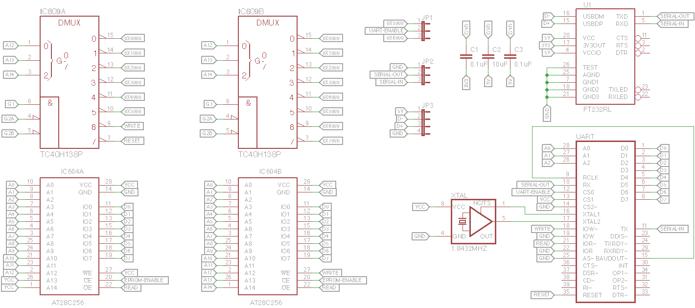
Since I'm actually working on making boards and easy to follow schematics, I've ditched the "visualized" concept from before in favor of a cleaner, simplified schematic. This is what I'll be wiring up my prototype boards with as soon as the digikey order gets here.
Some details of this schematic:
IC609A / IC604A are header pins meant to plug into sockets where those two chips used to be -- IC609B / IC604B are the chips located on the "daughter" board
FTDI USB->Serial (meaning the ECU will be USB, and you won't need an external adapter)
JP1 - Allows changing the UART memory address between 0x5000 to 0x6000
JP2 - TTL level serial output (if you already have a FTDI adapter/connecting to a raspberry pi/have some use for TTL and don't feel like spending money on the FTDI IC)
JP3 - USB cable header
IC609 has a number of unconnected pins on the ECU board -- this is great for bringing in signals rather than having to run wires from the ECU board to the daughter board
I'll be using a single NVSRAM/EEPROM module instead of two -- mapped at 0x8000-0xFFFF (the same as the S5's). This will effectively double the ROM space over stock, giving plenty of room for serial communications and other mods. Additionally, I've laid out all the required wiring additions on the board for both the N/A and TII -- both should be able to use the same boards once this is all said and done.
Since I'm actually working on making boards and easy to follow schematics, I've ditched the "visualized" concept from before in favor of a cleaner, simplified schematic. This is what I'll be wiring up my prototype boards with as soon as the digikey order gets here.
Some details of this schematic:
IC609A / IC604A are header pins meant to plug into sockets where those two chips used to be -- IC609B / IC604B are the chips located on the "daughter" board
FTDI USB->Serial (meaning the ECU will be USB, and you won't need an external adapter)
JP1 - Allows changing the UART memory address between 0x5000 to 0x6000
JP2 - TTL level serial output (if you already have a FTDI adapter/connecting to a raspberry pi/have some use for TTL and don't feel like spending money on the FTDI IC)
JP3 - USB cable header
IC609 has a number of unconnected pins on the ECU board -- this is great for bringing in signals rather than having to run wires from the ECU board to the daughter board
Thread Starter
Joined: Dec 2001
Posts: 10,630
Likes: 3
From: NY, MA, MI, OR, TX, and now LA or AZ!
While waiting for parts to arrive, I've been going over the N333 disassembly (EPROM's marked 0376 & 0387) and labeling everything. This has been made considerably easier thanks to the 16paws website which had a tremendous amount of work done on the S4 N/A ECU -- most of which is similar on the TII, so it's fairly easy to identify routines.
I have many of the basic tasks worked out -- such as eliminate AWS, adjust or remove the boost cut (I may see about changing this to an ignition based cut), adjust timing tables, memory addresses for various sensors/values for datalogging, adjustable sensor correction values, etc. I need to play around with staging more on the bench, but that shouldn't be too far off either.
I have many of the basic tasks worked out -- such as eliminate AWS, adjust or remove the boost cut (I may see about changing this to an ignition based cut), adjust timing tables, memory addresses for various sensors/values for datalogging, adjustable sensor correction values, etc. I need to play around with staging more on the bench, but that shouldn't be too far off either.

Senior Member
Joined: Apr 2009
Posts: 311
Likes: 2
From: Lynchburg, VA
Nice work, and a good idea on swaping over for straight USB, leaves for faster updates for real time logging/updating ecu.
If I am reading what your saying correctly we will be rewiring/adding to the ecu correct? Are you thinking of making it a daughter board that gets added or just using the free space on the ecu currently?
If I am reading what your saying correctly we will be rewiring/adding to the ecu correct? Are you thinking of making it a daughter board that gets added or just using the free space on the ecu currently?