
Column Mounted Switchgear- A Journey Into Madness

Tamper-proof torx, in case anyone was wondering what he's talking about. Most parts or tool stores sell them. Harbor freight is where I bought mine. They have an entire kit of "security" bits, and since I RARELY ever use them, I figured HF was good enough.
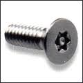
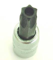
Yup, that's them awright...I stopped at HF on the way to the yard.
And didn't even need 'em.
The same capricious gnome that ate my Altima last week puked out a 2007 Mazda 6 overnight and Mazda uses a standard 8mm head on the airbag.
I got the entire switch,clockspring, pigtails and surround and confirmed that it is in fact, the same part used on some late model Subarus.
No real obvious way to mount it easily, so I'll be pondering that next.
I've only needed T-Torx for one job before. The MAF sensor on my Audi got dirty and I needed to pull it apart to clean it. In order to get the sensor element out of the housing, you need a T-Torx bit. I can't see myself using the set ever again.
I wonder how many multifunction switches you're going to collect by the time this is all done with
I wonder how many multifunction switches you're going to collect by the time this is all done with
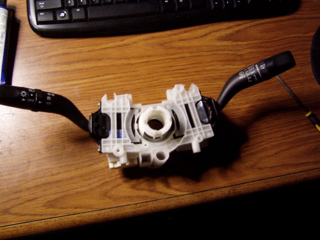
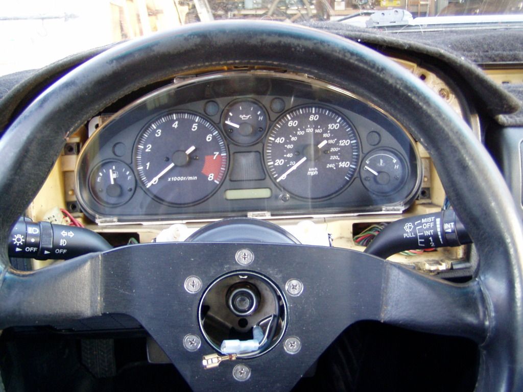
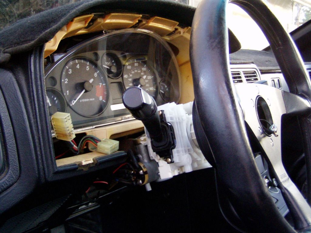
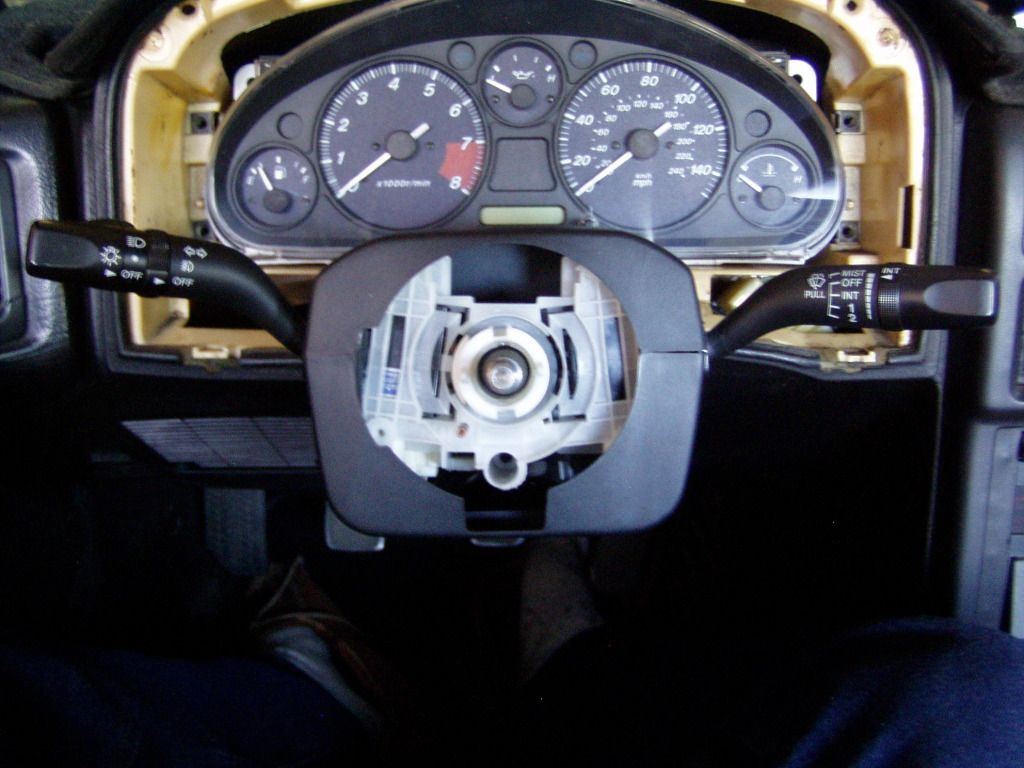
Pondering over, switch ready to install.
Hee, hee, hee.
Here's an exploded view of the 2007 Mazda 6 (and Miata, presumably) combination switch:
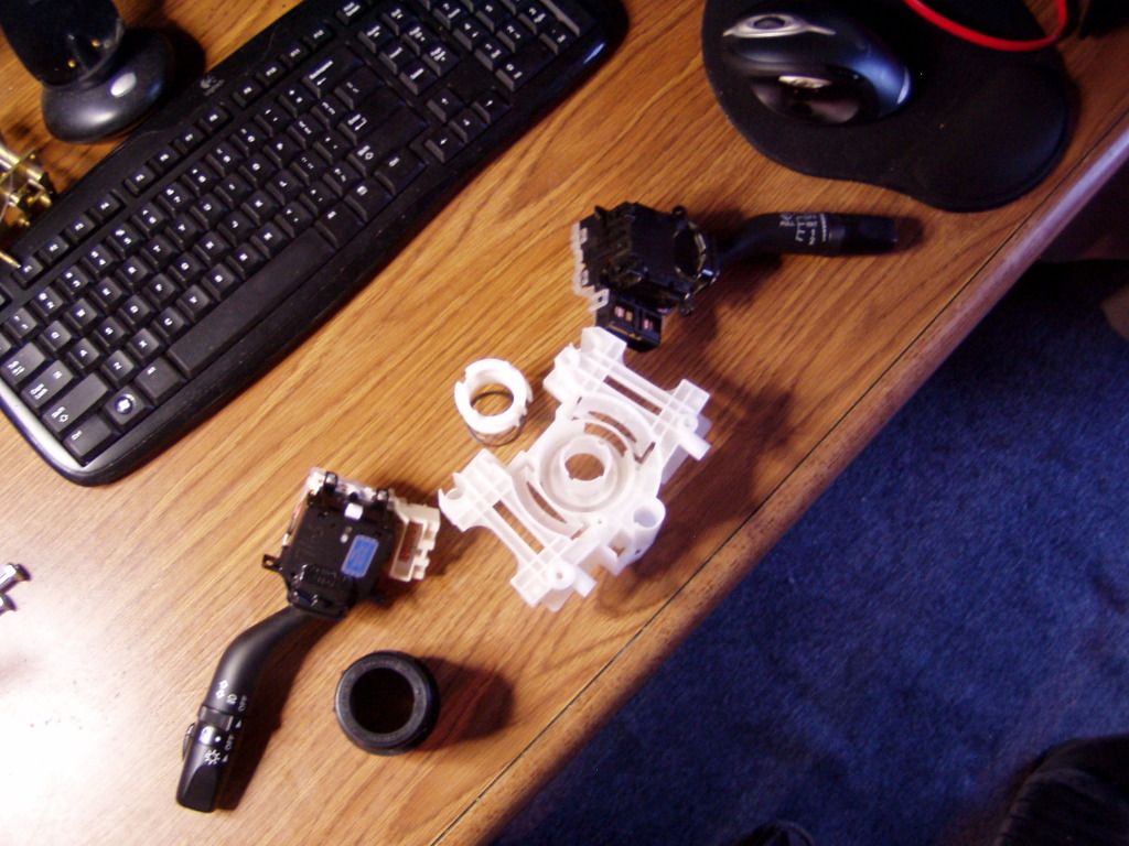
I don't think I'll be using the clockspring, so it's not pictured.
Originally, these switches mount to a rather elaborate structure that is part of the ignition switch...yeah well, **** that.
I wanted something as simple as the first 626 switchset, so I decided to duplicate it as closely as possible.
Properly fortified I moseyed over to my local custom parts emporium, Home Depot.
Underneath it's plebian plumbing exterior, this ABS sink fitting was actually a Miata mounting accessory...it just didn't know it.
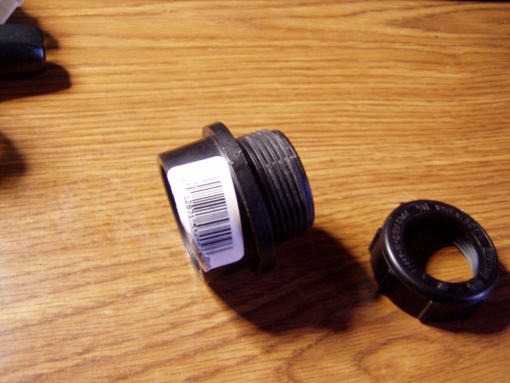
About a half hour of lathe time and it's true nature was exposed:
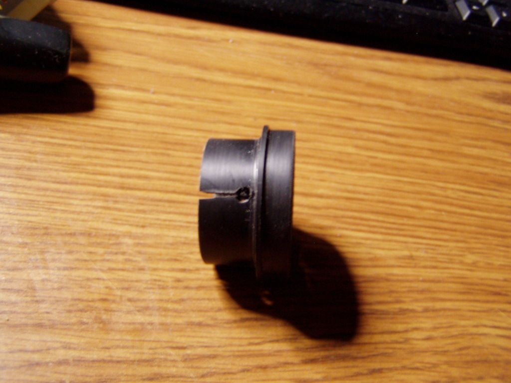
The larger diameter end was shortened and slightly turned down (@ .020") to fit the recess in the back of the bracket.
The threads were machined off the smaller end and four slits cut...this is the collar the clamp fits on.
I spread a thin layer of GOOP on the collar and pressed it in.
With the clamp in place:
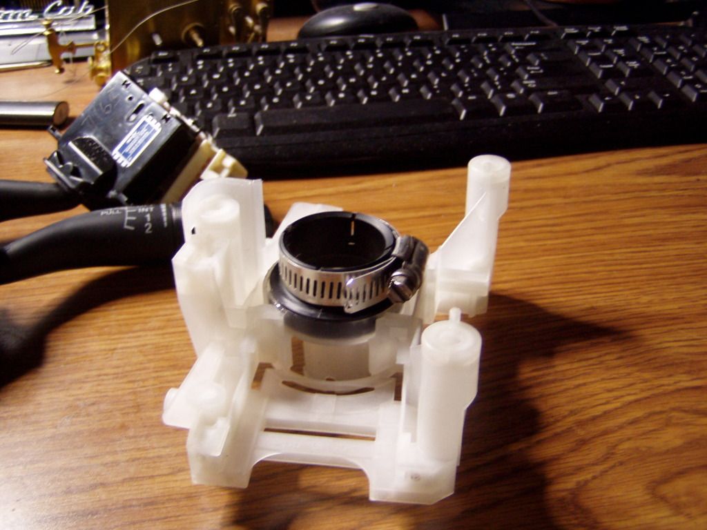
And reassembled:
I'll have it in the car in the morning.
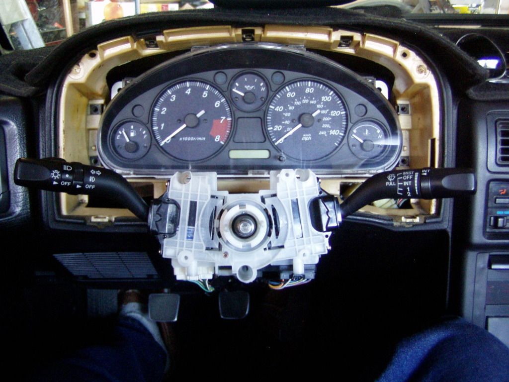
It's morning, so wake up sleepyheads!
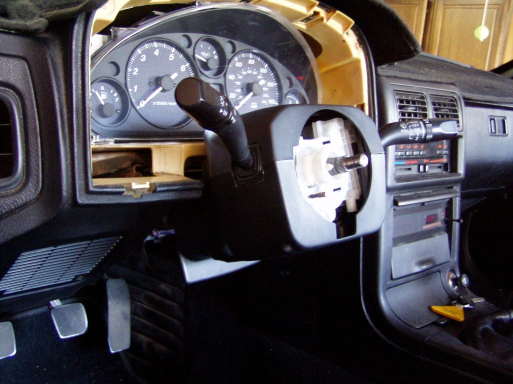
So far everything is working out just fine:
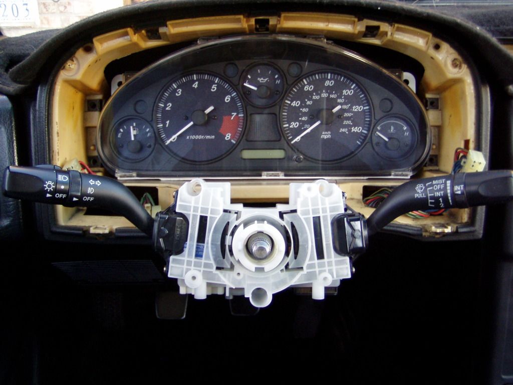
Access to the clamp is restricted, so the HL stalk/switch was was removed (two easily reached screws) to tighten it up.
Copacetic, near as I can tell.
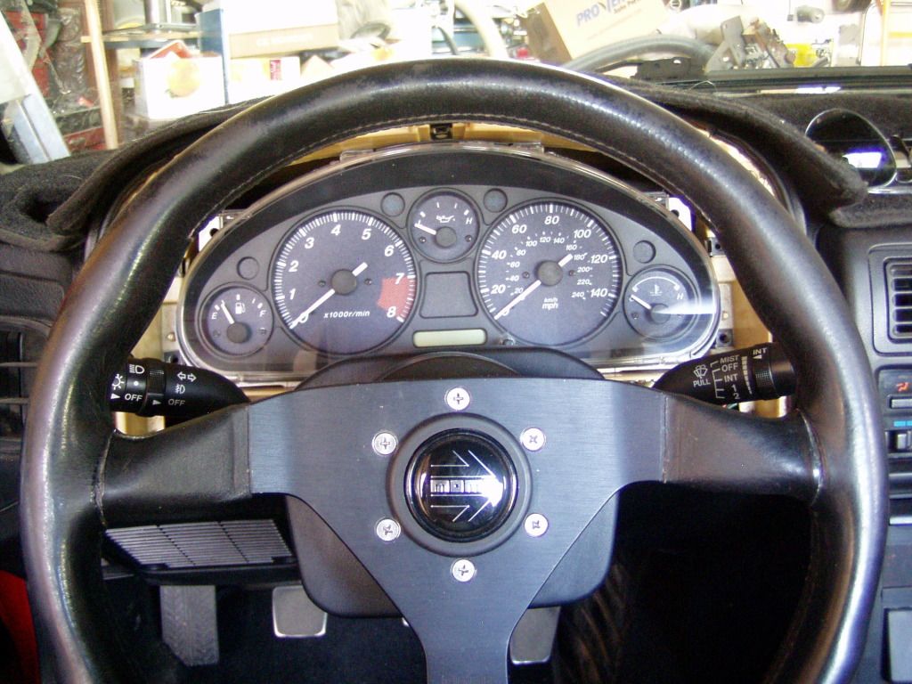
Wheel in place to show stalk>wheel relation:
About the switches:
-The headlight switch is completely mechanical, so I'll have to do some relay work to get the popup motors working.
-My light switch has a secondary fog lamp switch built in. I also saw these with rheostats for gauge light control, so there are options.
-The T/S switch has a circuitboard and I'm fervently praying it will be a direct plug-n-play.
All the wire colors in my pigtail correspond very closely with the FC wiring, maybe Mazda did me a favor.
-The turn signal switch is also available with cruise, if one is so inclined.
All of these switches are abundant on eBay for @$40/shipped.
With the switch physically in position, I can now explore two different avenues.
First, I need to decide about the horn- clockspring or slipring?
The clockspring is simplest because it bolts on and it's done, but I hate them on principle and it complicates wiring (I'd have to use the 6 pin connector to carry just a single wire).
It also hangs below the main bracket which interferes with my next path...
Although I did scavenge the switch surround from the Mazda 6 donor, it's a very poor fit/match for the FC. Way too big and bulbous, a stylistic dissonance.
The surround from the Nissan Altima is a much better look but naturally, would require work to fit. One area where there's no room to spare is below the switchbody, right where the clockspring sprouts it's connectors.
I can do the clockspring or the Altima surround, but I don't think both together are possible.
Random side tidbit...
The stock FC wheel is drilled to accept the transfer collar studs at the 6 and 12 o'clock position. This switch is configured for 3 and 9 o'clock, so the wheel will have to be redrilled.
Two minutes on a drill press, done.
Now, back to the junkyard.
So far everything is working out just fine:
Access to the clamp is restricted, so the HL stalk/switch was was removed (two easily reached screws) to tighten it up.
Copacetic, near as I can tell.
Wheel in place to show stalk>wheel relation:
About the switches:
-The headlight switch is completely mechanical, so I'll have to do some relay work to get the popup motors working.
-My light switch has a secondary fog lamp switch built in. I also saw these with rheostats for gauge light control, so there are options.
-The T/S switch has a circuitboard and I'm fervently praying it will be a direct plug-n-play.
All the wire colors in my pigtail correspond very closely with the FC wiring, maybe Mazda did me a favor.
-The turn signal switch is also available with cruise, if one is so inclined.
All of these switches are abundant on eBay for @$40/shipped.
With the switch physically in position, I can now explore two different avenues.
First, I need to decide about the horn- clockspring or slipring?
The clockspring is simplest because it bolts on and it's done, but I hate them on principle and it complicates wiring (I'd have to use the 6 pin connector to carry just a single wire).
It also hangs below the main bracket which interferes with my next path...
Although I did scavenge the switch surround from the Mazda 6 donor, it's a very poor fit/match for the FC. Way too big and bulbous, a stylistic dissonance.
The surround from the Nissan Altima is a much better look but naturally, would require work to fit. One area where there's no room to spare is below the switchbody, right where the clockspring sprouts it's connectors.
I can do the clockspring or the Altima surround, but I don't think both together are possible.
Random side tidbit...
The stock FC wheel is drilled to accept the transfer collar studs at the 6 and 12 o'clock position. This switch is configured for 3 and 9 o'clock, so the wheel will have to be redrilled.
Two minutes on a drill press, done.
Now, back to the junkyard.
This is an error, I meant to say that the wiper switch has a circuitboard.
So far, it's going quite smoothly.
The turn signals are connected and working.
The horn works.
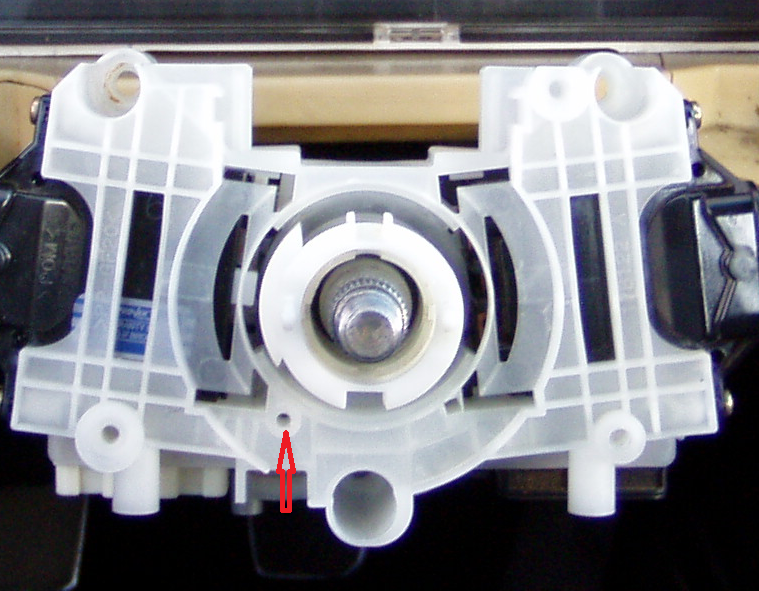
As I looked at the pics of the bracket, I saw a hole that looked suspiciously convenient for a spring loaded horn contact.
I removed the stocker from the FC switch (didn't lose the Tinkerbell sized e-clip either!) and it slid right into the new bracket, works perfectly, no modifications.
Here's a shot of the hole:
So far, it's going quite smoothly.
The turn signals are connected and working.
The horn works.
As I looked at the pics of the bracket, I saw a hole that looked suspiciously convenient for a spring loaded horn contact.
I removed the stocker from the FC switch (didn't lose the Tinkerbell sized e-clip either!) and it slid right into the new bracket, works perfectly, no modifications.
Here's a shot of the hole:
The headlight motors are easy, here's how it works:
First of all, realize that you don't need to tell the motors to stop, they have built in limit switches that do that automatically.
All you need is to activate UP and DOWN.
The default position is DOWN and the tool you need is a simple 5 pin relay where one pin is always hot.
This always hot lead goes to the DOWN contact on the motor(s).
The relay is activated by current from the LOW beam headlight circuit and this switches power to the second output of the relay which powers UP on the motors.
Turn of the lights and the retractor relay returns to it's natural state...power on to the DOWN circuit, so the motors retract and turn off.
The fact that the retractor is tied to LOW beam only explains how FTP works.
When you turn on your HIGH beam the LOW beam circuit remains active.
Remember, it's LOW beam only that controls the retractors, HIGH has noting to do with it.
The FTP switch bypasses the regular sequence and only powers HIGH, the lights flash but the retractors haven't seen a signal from the LOW beam, so they don't move.
This relay is built in to the stock switch, I'll just externalize it ...the wiring will be the same.
I was fortunate to easily find diagrams for the Mazda 6 switches.
The wipers look simple, pretty much just wire > wire interface with the FC harness.
The lights are more complex, not just because I have to add in the retractor relay but the 6 has some sort of auto light computer (lights on after car is off? automatic ON?...who knows) and most of my switch leads are supposed to go to it.
So, in order to see what is actually going on I'll need to ohm all the contacts and decipher the wiring myself.
How hard can it be?
Here's what's happening with the wiper switch.
The FC and Mazda 6 systems work exactly backwards.
The FC switch is providing grounds for everything, the Maz 6 is pushing power.
Everything in the new switch is a simple mechanical make/break contact, with the exception of the intermittent function.
This means that by simply reversing power with ground, all the normal functions work, LOW, HIGH, WASH, MIST, & PARK.
The intermittent system is on a circuitboard piggybacked onto the switch.
In the above config (putting ground where the switch expects to see power) the circuitry can't work because it's getting no power.
It appears that there are only two connections between the mechanical side of the switch and the circuit board. I'm hoping that if I reverse these the intermittent relay will become functional. If not, and even if the circuitboard fries, the mechanical switch should still work.
That's the plan.
And the plan didn't work.
I'm an electrical, not electronic, kind of guy, so that was the extent of my ideas.
The only other option I can think of is to add a layer of relays between the switch and the wiper motor. That way I could feed the switch the +12v it expects to see and use the switch outputs to trigger the relays which would apply grounds to the motor.
Seems like an awful lot of work to enable a function I rarely use.
I'll not give up on the intermittent function but I am going to ignore it for the nonce.
Everything else works fine and the headlight circuit beckons- once the lights work the car is fully driveable without any of the FC bezel mounted switchgear.
What I'm considering "sub" functions- panel lamp level, hazards, rear defrost and light UP- will also be addressed at a later date. What kind of switches and where they are located will depend a lot on the bezel I end up with, so work on that has to begin first.
I've just been splicing my pigtails with the proper male end to mate with the stock FC connectors and then plugging them in manually (no housing).
It looks like this whole project can be done without permanently changing the stock harness, reversion to stock switches is just a matter of plugging them in.
Like I care.
The headlight switch was a bitch but I've got her sussed now.
The new Mazda 6 switch does nothing but provide grounds, the FC switch provides grounds for the LOW/HIGH beam relays but actually powers the TNS -Tail,Numbers (license plate lights), Side.
I have yet to add the retractor relay but the headlamps work as does FTP.
To make the running lamps work I'll need to add a relay triggered by the switch.
After I'm finished I'll struggle with Paint and make a diagram showing what had to be done.
It's really not very complex, just hard to describe with words.
Now I need some relays...
Wow. Sounds like popup headlight circuits aren't as shitty as I thought they were. I remember from years ago I found a DIY "sleepy eye" control box. The circuitry inside that thing was absolutely crazy, and probably way more complex than it needed to be. That's what really scared me about it. I've since grown... distant... to the sleepy eye look.
I may not be getting what you're talking about with the wiper wiring, but it'd seem as if you'd rewire the wiper motors to have constant power, you'd be able to use the Mazda 6 wiper switch the way it's designed to work with no modifications to it, other than switching around the wires to the connector. It really is hard to describe, and a drawing would help tremendously here; but, then again, you're a big boy, and I'm sure you can figure it out
I may not be getting what you're talking about with the wiper wiring, but it'd seem as if you'd rewire the wiper motors to have constant power, you'd be able to use the Mazda 6 wiper switch the way it's designed to work with no modifications to it, other than switching around the wires to the connector. It really is hard to describe, and a drawing would help tremendously here; but, then again, you're a big boy, and I'm sure you can figure it out
I have to go junkyarding again tomorrow to find some cute relays.
My whole (depleted) stash consists of Volvo 40A units...they're very nice but overkill (and too big) for this application. I'm guessing I can find a nice two relay box in something that will fit the bill...I hope.
At the same time I'll hunt down another wiper stalk.
If I have a backup I'll be more adventurous trying to get intermittent to function.
I didn't find another wiper stalk but I don't think it'd matter anyway.
I was fooling around with the switches (like you do) and noticed a glitch in the wiper setup.
WASH does activate the pump but the wipers don't move.
I'm thinking this timed wiper activation is performed by the (currently) dead intermittent circuit.
Which kind of tees me off.
I might cobble together a layer of relays and see if that fixes everything up.
The lights are now fully functional, retractors, TNS and all.
That side of the harness (T/S & Lights) terminates at a connector just under the dash, so I felt more comfortable cutting/soldering the new additions knowing I could replace that little subharness and be back to stock. The wiper side hasn't been modified.
With the wiring done it's time to move to the finish work.
Going to start with the column surround trim first.
Right now, LOW, HIGH and MIST all work.
The WASH pump works, it just doesn't activate the wipers with it.
INTERMITTENT is a non starter.
I'm going to try a second approach on the wipers that I think will get everything back to stock function, I tried the easy way first and only got 75% of the way there.
The WASH pump works, it just doesn't activate the wipers with it.
INTERMITTENT is a non starter.
I'm going to try a second approach on the wipers that I think will get everything back to stock function, I tried the easy way first and only got 75% of the way there.
A random musing...
My headlight stalk incorporates a FOG lamp switch (other versions delete the FOG and replace it with a panel light control rheostat).
This switch would make a very stealthy fuel cut control if one was so inclined.
Just sayin.
My headlight stalk incorporates a FOG lamp switch (other versions delete the FOG and replace it with a panel light control rheostat).
This switch would make a very stealthy fuel cut control if one was so inclined.
Just sayin.

The Mazda 6 switch looks right at home with your MX-5 cluster. As it should, as everything is all the same manufacturer here. For anyone wanting a more stock-ish FC orange look, the older Mazda stalk would have been a good choice.
Right now, LOW, HIGH and MIST all work.
The WASH pump works, it just doesn't activate the wipers with it.
INTERMITTENT is a non starter.
I'm going to try a second approach on the wipers that I think will get everything back to stock function, I tried the easy way first and only got 75% of the way there.
The WASH pump works, it just doesn't activate the wipers with it.
INTERMITTENT is a non starter.
I'm going to try a second approach on the wipers that I think will get everything back to stock function, I tried the easy way first and only got 75% of the way there.
I triple checked my wiring and it conforms to the diagram I'd made, so I'm left with two options:
-Reevaluate my concept and find the problem. It occurs to me that I may have damaged the switch circuitboard during my initial hookup attempts, so that's a possibility also.
-Delete the much more complex "fix" and return to the initial config which gave me everything but INT and wipers during WASH.
For the moment I'm very tempted to revert to simple and move on.
Forum member j9fd3s has kindly hooked me up with a vert gauge bezel, which I'm hoping will fit with the stalks.
When I did the last cluster swap I had tried a different method which involved cutting the bezel rather than modify the cluster housing. I'm loathe to mess with the new bezel, so I'm going to redo the gauges now, hopefully done by the time the bezel arrives.
So I still have much to do.
I'll let the wiper schematic percolate in my head, maybe inspiration will strike.
Here's where I am right now...
I redid my wiper harness, reverting back to the "mostly working" state.*
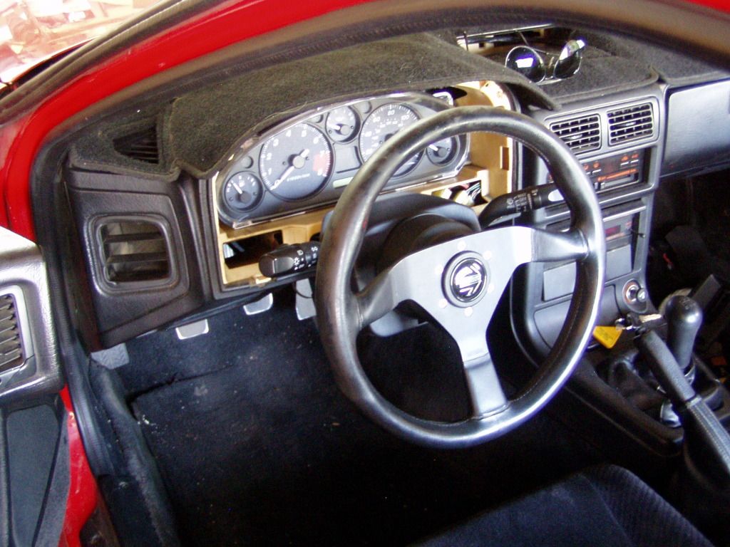
She's all hooked up here:
Surround trim installed:
With steering wheel:
*Just in case some one has the time/talent/inclination, here are the schematics for the FC wiper system and the Mazda 6.
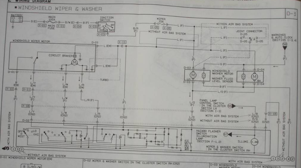
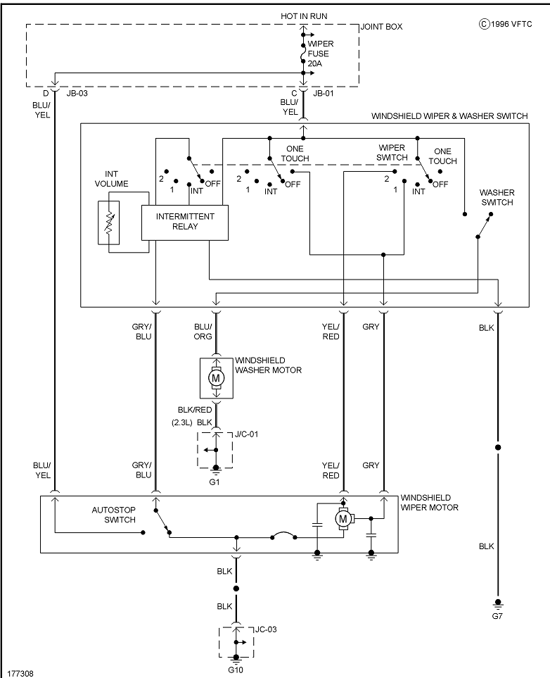
My current config is as follows:
FC harness > M6 switch
L/Y > Gr/B (park/autostop)
L/O > L/O (washer pump)
L/R > Y/R (high speed)
L/W > Gr (low speed)
B > L/Y (ground)
If anyone can figure out a better way to hook this up, I'd really appreciate it.
I redid my wiper harness, reverting back to the "mostly working" state.*
She's all hooked up here:
Surround trim installed:
With steering wheel:
*Just in case some one has the time/talent/inclination, here are the schematics for the FC wiper system and the Mazda 6.
My current config is as follows:
FC harness > M6 switch
L/Y > Gr/B (park/autostop)
L/O > L/O (washer pump)
L/R > Y/R (high speed)
L/W > Gr (low speed)
B > L/Y (ground)
If anyone can figure out a better way to hook this up, I'd really appreciate it.
Progress limps along.
The vert gauge bezel arrives today and in preparation I tackled the cluster integration again.
The first attempt at this proved it could be done but that I had done it badly.
Learning from those mistakes, this time I made fixtures/jigs and different tooling setups which made things a lot easier.
It's still not perfect (short of making the whole thing from scratch, it really couldn't be) but the fit (and therefore, the glue up) are much better.
Acceptable, actually.
There are still details to complete but the cluster is able to be installed and that was the immediate goal.
With the gauges in place, the new bezel can go on (untouched) and the column trim final fitted.
Most of the previous pics show a Momo steering wheel but that's not the wheel I'll be using, so the new part (from a 626, IIRC) is being prepped for install.
The transfer holes have already been redrilled (dead simple on a drill press-assuming you have enough throat- but certainly do-able by hand) and I'm making the horn slipring today.
Deleting the bezel mount switches will leave me to fill six holes in the bezel.
My initial plan is to pop in rubber body plugs (another junkyard trip), we'll see how that works cosmetically.
As for the little lit viewports in the bezel face...well, I have no idea.
A moderately ambitious plan would move the idiot cluster warning lights into these windows.
That's just a thought...I shan't be doing that because the Miata cluster already has all the warning lights I need.
/mini datadump

Rotary Enthusiast

Joined: Jan 2002
Posts: 845
Likes: 38
From: Oscoda, MI
On the trim piece, what about using pieces of black ABS plastic welded into place using a product like Plastex. Then use some kind of plastic-compatible filler and spray the whole thing in a coat of rubberized or trim black.
I'll start the weekend with a shout out to forum member j9fd3s, who offered up a vert bezel to the project.
Perfect condition part, well packaged and quickly shipped...very nice, thank you.
It breaks my heart to say that it doesn't really fit though.
That said, I'm still better off with this piece since my old one had been hacked to fit my unsuccessful second gauge install. The cluster will look much better, regardless of what happens with the stalks.
A little less hope and a bit more logic and I'd have seen it coming.
The vert H/L and wiper switches are still trying to occupy the same space as the new stalks.
You'll see what I mean in a bit.
Going to trim the surround to fit and mount it up for some pics later.
@cluosborne:
I researched plastic repair for the first gauge integration project.
This time I used proper ABS solvent cement and mixed up some homemade ABS "bondo".
Take small chips/pieces of ABS plastic and put them in a glass container, add acetone.
The acetone will dissolve the ABS into a paste (you control the consistency by adding more plastic or more solvent), that can fill gaps and add structure...it literally melts into the parent material.
Like Bondo, this works best in multiple applications rather than one fat layer, so it does take some time.
I had hoped- and still do- to avoid extensive cosmetic work on the bezel, so I'm back in full THINK mode, looking for an easy way out.
I feel the need for a contemplative walk through the junkyard...