
Monsterbox's 20b FD3S Conversion

Thread Starter
Mazzei Formula
iTrader: (6)
Joined: Jun 2006
Posts: 3,021
Likes: 145
From: Birmingham, Al
If you have back firing and the #2 runner is hot, its not timed properly. At this point you're only checking timing of #1, so #2 and #3 could be off. My advice is to mark the pulley at 120� increments from the #1reference and then check to see if #2 and #3 are actually in time. With what you describe, at the least, #2 is not.
So if I lock it at -5, and then mark 120* from the -5 marking around the pulley, and crank the motor with timing light, switching the light to L2 and finally L3, this is what your saying right?


Correct.
I won't comment on why the timing wouldn't synch without throwing in an offset value. But, in the end, if it does synch and doesn't drift, that is all that matters.
I won't comment on why the timing wouldn't synch without throwing in an offset value. But, in the end, if it does synch and doesn't drift, that is all that matters.
Thread Starter
Mazzei Formula
iTrader: (6)
Joined: Jun 2006
Posts: 3,021
Likes: 145
From: Birmingham, Al
the fact it was 25 degrees screams that you and or the original guy who proposed the trigger timing numbers have the CAS dropped in one tooth different to each other,, and the other guy used a genuine TDC as a datum
each tooth moves things 30 degrees,, hence 30 - 5 = 25 degrees difference in your setup
if the CAS dropped back one more tooth,, then timing will be spot on
neither is wrong or right.. you move the trigger offset to suit the CAS position and confirm with timing lock and light
both will work ,, the only trick is leaving ( at least in terms of motec and haltech )
that minimum window of at least 45 degrees in the trigger angle so the ECU can have scope to advance the timing
When you say the "other guy", do you mean the ECU trigger timing numbers may have possibly been set to a baseline that was 25* offset from factory?
All this trigger angle timing stuff is relatively new to me. I'm used to plugging stuff in, loading a basemap, and taking it down the road.
Its starting to be a possibilty of what C. Ludwig said above. If I had offset the timing -25 to line up L1, it seems as if L1 is locked down but now L2 has been retarded off synch by that adjustment...
Going to mark this damn pulley all the way around and see what we get tonight!
Thread Starter
Mazzei Formula
iTrader: (6)
Joined: Jun 2006
Posts: 3,021
Likes: 145
From: Birmingham, Al
I spoke with Abel Iberras and Steve Khan. According to Abel, the markings on the 20b pulley cannot be trusted. Therefore, the assumption that the -5 marking is true -5 to lock the ECU down is not necessarily -5, as in his experience he's seen even FC factory motors be off by 15* with everything being locked accordingly.
His recommendation is to throw out all notions of these factory markings and find TRUE TDC. He believes the misfiring and the 25* offset issues is all related to the unknown -5 guestimate.
Khan suggested to remove the hub on the front cover and see the relation of the E shaft. Mark the pulley in relation to the E shaft so that the E shaft would have been facing 9 o clock and use this to verify TDC.
What do you think?
talking head
Joined: Apr 2008
Posts: 2,775
Likes: 15
From: Perth, WA, OZ
it means undoing the endfloat and that is extremely risky for new players
on 13b's , due to the 180 degree thing there used to be a method for gauging TDC using the rear rotor at its minimum position via the spark plugs
on 20's , with a 120 thing, that may be impossible
but i am sure you can use the position of the counterweight on the rear for a reliable gauge of TDC
( look down the inspection cover )
you may need another 20b user to confirm where it will sit
on a 13b, the the middle of the two bumps on the counterweight lay down the spark side of the motor at 9 ( or 3 ) oclock
PS
double check that when locked the timing does not move,, chris is hinting you may have the sensor pickup wiring incorrect at CAS
Last edited by bumpstart; Nov 18, 2014 at 12:27 PM. Reason: PS
Thread Starter
Mazzei Formula
iTrader: (6)
Joined: Jun 2006
Posts: 3,021
Likes: 145
From: Birmingham, Al
it means undoing the endfloat and that is extremely risky for new players
on 13b's , due to the 180 degree thing there used to be a method for gauging TDC using the rear rotor at its minimum position via the spark plugs
on 20's , with a 120 thing, that may be impossible
but i am sure you can use the position of the counterweight on the rear for a reliable gauge of TDC
( look down the inspection cover )
you may need another 20b user to confirm where it will sit
on a 13b, the the middle of the two bumps on the counterweight lay down the spark side of the motor at 9 ( or 3 ) oclock
PS
double check that when locked the timing does not move,, chris is hinting you may have the sensor pickup wiring incorrect at CAS
on 13b's , due to the 180 degree thing there used to be a method for gauging TDC using the rear rotor at its minimum position via the spark plugs
on 20's , with a 120 thing, that may be impossible
but i am sure you can use the position of the counterweight on the rear for a reliable gauge of TDC
( look down the inspection cover )
you may need another 20b user to confirm where it will sit
on a 13b, the the middle of the two bumps on the counterweight lay down the spark side of the motor at 9 ( or 3 ) oclock
PS
double check that when locked the timing does not move,, chris is hinting you may have the sensor pickup wiring incorrect at CAS

Before removing the hub, I think it would be most reasonable and least risky to try and locate TDC via spark plug holes. I've read another member on here using a Microtech on a 20b got damn near TDC by looking into L1 and T1. First he moved the crank until a visible apex seal appeared in L1 and marked the pulley, then again in T 1 and marked the pulley. Then equidistance between the marks is ~TDC.
I will try this and see how close it aligns to my stock pulley markings as a rough check for accuracy.
Thread Starter
Mazzei Formula
iTrader: (6)
Joined: Jun 2006
Posts: 3,021
Likes: 145
From: Birmingham, Al
Here's what I found from the member running a 20b w factory pulley and CAS:
Rotormaster Lynn Hanover and I did this on my car recently so it's fresh in mind. My timing marks had faded, so we went through the motions and found TDC the old fashioned way: getting one of the front rotor's apex seals between the spark plugs and marking the pulley. After that, the engine was turned back 5 degrees, marked again and then forward 20 degrees for a final mark. Now it has both stock marks, plus one for TDC.
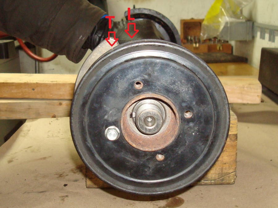
Just so we're clear, are you using FD pulleys and a FC's CAS? The procedure and timing marks are the same for both, it just looks like the mark to the right of the timing pin was added by a previous owner. So let's work with the other two pulley marks, as those appear to be original.
The timing mark on the right is for 5 degrees BTDC, the left mark is 15 degrees ATDC. Line up the mating marks just like you have it now (second pic), get the engine on the 5*BTDC mark, then stab the CAS in with the pointers exactly as you have them now (first pic). If the pointers inside the CAS move, adjust the body till they line up correctly. You should be all set then.
There is SOOOOO much misinformation on these markings.
Is it freaking -5 BTDC or 5 BTDC? This would make a 10* difference. I see these misquoted in just about every post on how to time your engine.
At this point, I wouldn't be suprised if half the FC guys are running around with 10* off time.
Rotormaster Lynn Hanover and I did this on my car recently so it's fresh in mind. My timing marks had faded, so we went through the motions and found TDC the old fashioned way: getting one of the front rotor's apex seals between the spark plugs and marking the pulley. After that, the engine was turned back 5 degrees, marked again and then forward 20 degrees for a final mark. Now it has both stock marks, plus one for TDC.
https://www.google.com/search?q=mazd...2F%3B640%3B787
Looks like it sits @ tdc or 5* i will have to look when i get mine apart
Looks like it sits @ tdc or 5* i will have to look when i get mine apart
talking head
Joined: Apr 2008
Posts: 2,775
Likes: 15
From: Perth, WA, OZ
aside all this TDC stuff,, i dont see how if the front is timed right ( to whatever mark ) then the middle rotor is out
all rotors will be out the same
if the middle is glowing then there is a few scenarios
the middle is hurt ( ouch )
the middle has a huge vac leak
the middle has a blocked injector
the middle is firing only on the trailing plug
the middle has its leading and trailing leads back to front
im leaning towards the bottom two , and you should confirm the order and colour of the trigger wires are all in order to rule out a misswire of the coil triggers
i suspect also that maybe the trailing only is working there , and to prove a bad connector join or plug then maybe you should run that rotor up with only the leading coil plugged in
if you lose the entire rotor , then there is something amiss with the leading plug, the HT wire, or the connector
talking head
Joined: Apr 2008
Posts: 2,775
Likes: 15
From: Perth, WA, OZ
https://www.google.com/search?q=mazd...2F%3B640%3B787
Looks like it sits @ tdc or 5* i will have to look when i get mine apart
Looks like it sits @ tdc or 5* i will have to look when i get mine apart
when the rotor is at max displacement to the compression side
im pretty sure the old 13b had the keyway at 9 oclock
Thread Starter
Mazzei Formula
iTrader: (6)
Joined: Jun 2006
Posts: 3,021
Likes: 145
From: Birmingham, Al
aside all this TDC stuff,, i dont see how if the front is timed right ( to whatever mark ) then the middle rotor is out
all rotors will be out the same
if the middle is glowing then there is a few scenarios
the middle is hurt ( ouch )
the middle has a huge vac leak
the middle has a blocked injector
the middle is firing only on the trailing plug
the middle has its leading and trailing leads back to front
im leaning towards the bottom two , and you should confirm the order and colour of the trigger wires are all in order to rule out a misswire of the coil triggers
i suspect also that maybe the trailing only is working there , and to prove a bad connector join or plug then maybe you should run that rotor up with only the leading coil plugged in
if you lose the entire rotor , then there is something amiss with the leading plug, the HT wire, or the connector
all rotors will be out the same
if the middle is glowing then there is a few scenarios
the middle is hurt ( ouch )
the middle has a huge vac leak
the middle has a blocked injector
the middle is firing only on the trailing plug
the middle has its leading and trailing leads back to front
im leaning towards the bottom two , and you should confirm the order and colour of the trigger wires are all in order to rule out a misswire of the coil triggers
i suspect also that maybe the trailing only is working there , and to prove a bad connector join or plug then maybe you should run that rotor up with only the leading coil plugged in
if you lose the entire rotor , then there is something amiss with the leading plug, the HT wire, or the connector
ALL 3 runners turned bright red, enough to scare me. Shut it down. When I got home I found the trailing plugs were completely fouled to the point that they wouldn't fire. The leadings were brand new. I chalked the red manifold up to being no trailing spark and thought nothing of it.
Last night, w new trailing and leading plugs we tried to fire it up and got the red middle runner, I didn't run it long enough to see if all three would turn red.
The car ran great the 1st night on leading only but horrible last night.
I pulled the plugs and they were pretty oil covered down to the porcelain after only a few mins of run time. But we def had spark on at least most of the plugs unless they can foul that fast.
I think the middle trailing or leading must have gummed up and stopped firing, but I don't understand why the car ran sSo bad and backfired under 3k rpm.
The compression sounds susuper crips on all rotors w leading plugs out.
I don't see aany obvious vaccuum leaks that would lead to the center rotor or cause that bad of a run-in.
talking head
Joined: Apr 2008
Posts: 2,775
Likes: 15
From: Perth, WA, OZ
well before you go further suggest you buy a mirror or borescope and
get yourself a set of cheaper 'run in' plugs
.. usually i recommend a lathed down spark plug tool and the NGK B9EGV or B9EG
( you can use the cheaper B9ES also , but i only trust them in the trailing hole and only for debugging /startup only )
locate TDC via spark plug holes. I've read another member on here using a Microtech on a 20b got damn near TDC by looking into L1 and T1. First he moved the crank until a visible apex seal appeared in L1 and marked the pulley, then again in T 1 and marked the pulley. Then equidistance between the marks is ~TDC.
I will try this and see how close it aligns to my stock pulley markings as a rough check for accuracy.
I will try this and see how close it aligns to my stock pulley markings as a rough check for accuracy.
.. usually i recommend a lathed down spark plug tool and the NGK B9EGV or B9EG
( you can use the cheaper B9ES also , but i only trust them in the trailing hole and only for debugging /startup only )
Thread Starter
Mazzei Formula
iTrader: (6)
Joined: Jun 2006
Posts: 3,021
Likes: 145
From: Birmingham, Al
I forgot to add, iv double checked last night that I do have correct trigger wiring to coils.
The most alarming thing is that all 3 were red when trailings weren't firing.
The most alarming thing is that all 3 were red when trailings weren't firing.
Thread Starter
Mazzei Formula
iTrader: (6)
Joined: Jun 2006
Posts: 3,021
Likes: 145
From: Birmingham, Al
Good advice, I guess it could be possible I'm just fouling the **** out of plugs and killing spark leading to red manifold and horrible idle quality.
Ngk r5671-9, supra plugs with adequate length to not need lathed socket, 5/8 head.
Ngk r5671-9, supra plugs with adequate length to not need lathed socket, 5/8 head.
well before you go further suggest you buy a mirror or borescope and
get yourself a set of cheaper 'run in' plugs
.. usually i recommend a lathed down spark plug tool and the NGK B9EGV or B9EG
( you can use the cheaper B9ES also , but i only trust them in the trailing hole and only for debugging /startup only )
get yourself a set of cheaper 'run in' plugs
.. usually i recommend a lathed down spark plug tool and the NGK B9EGV or B9EG
( you can use the cheaper B9ES also , but i only trust them in the trailing hole and only for debugging /startup only )

I figure this will be helpful for people searching in the future.
There are problems with the e-shaft pic being referenced. The 20B does not have a front hub bolt, it has a large nut, which leads me to believe that is not a real 20B shaft.
Here is a real 20B e-shaft being held at TDC, with the CW's and hub assembly attached.
Notice the CWs are offset, unlike the 13B which has the keyway in the center. This is the reason 20B front and rear CWs are mandatory when assembling.
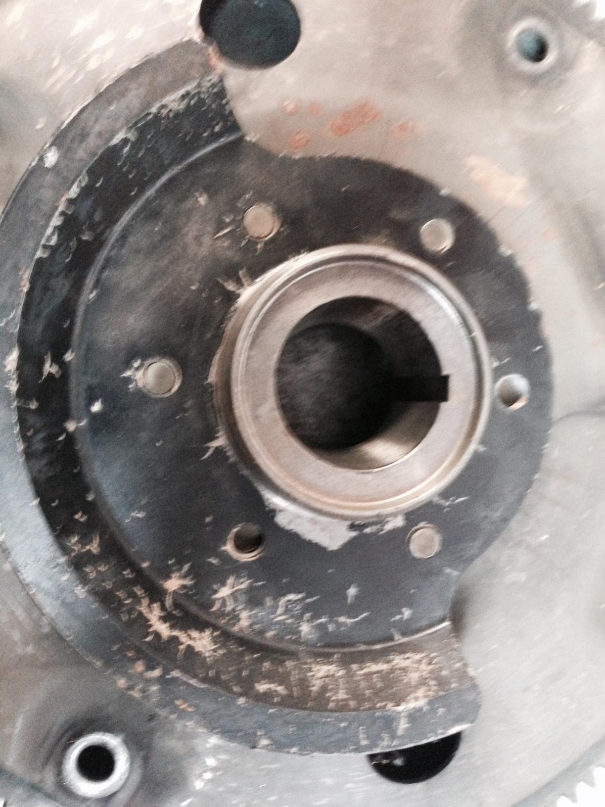
E-shaft being held at TDC

Front keyway is at 9:00, timing marks identified for reference
Rear CW keyway is at 3:00, notice it is aligned with the bolt.

There are problems with the e-shaft pic being referenced. The 20B does not have a front hub bolt, it has a large nut, which leads me to believe that is not a real 20B shaft.
Here is a real 20B e-shaft being held at TDC, with the CW's and hub assembly attached.
Notice the CWs are offset, unlike the 13B which has the keyway in the center. This is the reason 20B front and rear CWs are mandatory when assembling.
E-shaft being held at TDC
Front keyway is at 9:00, timing marks identified for reference
Rear CW keyway is at 3:00, notice it is aligned with the bolt.
Last edited by Banzai-Racing; Nov 19, 2014 at 09:41 AM.
Thread Starter
Mazzei Formula
iTrader: (6)
Joined: Jun 2006
Posts: 3,021
Likes: 145
From: Birmingham, Al
Going to purchase these NGK 5820 - 10 Heat range piston type plugs cheap $2.50 shouldn't foul as bad as the surface discharge type.
Has anyone used the spark plug non-fouler/arresters? These go in before the plug and prevent fouling. Its an aluminum spacer that keeps the plug from seeing oil. Safe to use?
Has anyone used the spark plug non-fouler/arresters? These go in before the plug and prevent fouling. Its an aluminum spacer that keeps the plug from seeing oil. Safe to use?
talking head
Joined: Apr 2008
Posts: 2,775
Likes: 15
From: Perth, WA, OZ
problems with the e-shaft pic being referenced. The 20B does not have a front hub bolt, it has a large nut, which leads me to believe that is not a real 20B shaft.
to the OP .. do not use alum spacers in the plugs
and probs best to stick with some of those plugs i have recommended
as they are cheap, and they work , and are known to hang in there in a rotary engine environment
and the EG is around $10 -$12
and the ES is $2 - $4
i have much faith in the EG, being able to survive multiple floods and not put a porcelain into the motor
the ES i have less faith , and use them in the trailing side where a porcelain fail cannot enter the engine unless you are especially unlucky
both of these you can find also with an "R" code ( BR9EG ) so they are compatible
( in the long term ) with your ECU , noise wise
however , for startups, i tend to go for the noisy non resistive ones , as it is about the best spark to get around initial bad mixtures
once things get close, and starting more reliable move to the resistive groups of plugs
//
using the new 20b pics, you can probs see that if you align two of the nearly vertical hub bolt holes with a straight edge
and knowing that these CAS engines used a 5 and 20 ATDC marks
then you end up with a mark that looks to be very close to 10 ATDC
from there the only way you will get more accurate is to look through the leading and trailing spark holes for the apex seals and measure the equidistant
Thread Starter
Mazzei Formula
iTrader: (6)
Joined: Jun 2006
Posts: 3,021
Likes: 145
From: Birmingham, Al
appears the original link has four rotor lobes as well !!
to the OP .. do not use alum spacers in the plugs
and probs best to stick with some of those plugs i have recommended
as they are cheap, and they work , and are known to hang in there in a rotary engine environment
and the EG is around $10 -$12
and the ES is $2 - $4
i have much faith in the EG, being able to survive multiple floods and not put a porcelain into the motor
the ES i have less faith , and use them in the trailing side where a porcelain fail cannot enter the engine unless you are especially unlucky
both of these you can find also with an "R" code ( BR9EG ) so they are compatible
( in the long term ) with your ECU , noise wise
however , for startups, i tend to go for the noisy non resistive ones , as it is about the best spark to get around initial bad mixtures
once things get close, and starting more reliable move to the resistive groups of plugs
//
using the new 20b pics, you can probs see that if you align two of the nearly vertical hub bolt holes with a straight edge
and knowing that these CAS engines used a 5 and 20 ATDC marks
then you end up with a mark that looks to be very close to 10 ATDC
from there the only way you will get more accurate is to look through the leading and trailing spark holes for the apex seals and measure the equidistant
Thanks for the advice.
I won't be using any spacers and ill go with those plugs. Marked the pulley for 120* orders and hopefully well have successful blast-off here in an hr or two!