When you click on links to various merchants on this site and make a purchase, this can result in this site earning a commission. Affiliate programs and affiliations include, but are not limited to, the eBay Partner Network.
Are you running an AGM type battery? If so, those generally need to be charged more aggressively to get them to full charge, i.e., 14.5-->15-ish volts or more (cyclic), depending on battery temp. (Refer to you battery manufactures real tech literature for charging specifics.) Any battery's performance and potential life will fall off rapidly if it isn't fully charging.
I should also mention that the internal regulator in the common automotive alternator is designed to charge standard lead acid batteries and includes temperature compensation or a gradient to reduce the output (charging) voltage as the temperature increases. Now consider that the alternator is in a hot engine compartment: the assumption designed into these internal regulators is that the battery is co-located in the engine compartment and that the regulator's temperature tracks that of the battery; thus functioning as a system to maintain the correct charging voltage.
Therefore, if you have a relocated battery (of any type), you probably need to charge more aggressively to maintain full charge. Again, the reason is that your battery is likely going to be much cooler than it would be if near the alternator and since batteries are properly charged with reference to their temperature, there is now no thermal feedback loop to offset this change to a cooler environment. This will result in an undercharge unless you increase the alternator's output voltage somewhat to compensate. And if you have a relocated AGM battery, you've got a double whammie due to the fact that it requires a higher charging potential to begin with. While a few tenths of a volt may not seem like much, it is a significant percentage to a 12V system and a very big deal to getting a battery properly charged. The complications involved in relocating a battery to a cooler location, however, are usually far outweighed by an increase in battery life--if it is installed properly.
So how do you increase an alternators output voltage by a small amount? Simple, for internally regulated units (like our FDs) you change its reference voltage. To do this, locate the alternator's field/sensing lead that it uses for its voltage reference and to excite the alternator; often times this is hooked to a circuit coming from the ignition switch but it is NOT the one used for the warning light. Cut the wire, preferably near the alternator, and add a small forward biased diode for each ~0.6 volts you want to increase the output. For my own car, with a bin relocated AGM battery (PC925), I added 2 diodes in series to the stock FD alternator's field lead to increase the output approx 1.2 volts (to about 14.8V which is a more appropriate charging voltage for my setup (vs 13.6V without the mod). I used the 1n4001 series of general purpose rectifier diodes as they are small, rugged, work well, and are less than a $1 for both. If you have a super high current alternator, you may need to double them up or use higher current rated diodes; you can measure this in the field lead.
T-von, it sounds like there's not enough field excitation provided by your alternator's regulator and/or not enough rotor core volume. Additionally, regulators usually have current limiting built in to protect the alternator from melt down; while this isn't a problem at speed, you need a lot more field current to get a high output at idle. Since the laws of physics dictate that an alternator's output will drop off with decreasing speed, you have to put more energy into the system and thus into field to make up for this--a technique that works, but has limitations. Real, purpose-designed high output, low speed alternators may also have larger rotors wound to handle this and may be larger in overall diameter (to increase surface speed and/or include more poles).
Wholy crap thx for all this info as I do run a AGM Braile B3121 in the bin.
13v and up is what you wanna see at idle so your good. Now do you see that same voltage when you start loading up the electronics? That's been my problem with this junky ebay unit. Like tuning on the blower on high, with the headlights, and cooling fans? Your alternator is suppose to supply enough amps at idle with all these things on.
Oh and I just now found another problem thats been plaguing me the last few weeks. Back in December, I upgraded to the IGN-1A coils. Well I accidentally dropped 1 when I was building my bracket. Fast forward to today. I have a spare Nissan Maxima alternator I decided to put on the car to see how well charges while I wait for my upgraded alternator to get re-upgraded. Lol! I go to start the car and it just turns over. I realize then that I accidentally disconnected my ignition coil ground from the block. Based on some info I got recently from C- lugwig, a couple months ago, I separated both sets of leading and trailing coils to two different 12v relay banks. Originally, I had all 6 coils on 1 20a fuse/relay. So when I turned the key over, the car still should have fired up on at least 1 set of coils but it didn't. You see I have both sets of coils grounded in separate locations and only one pack was disconnected. So I plug in that disconnected ground and then check my main Haltech ignition coil fuse. Sure enough it was blown. Hell no wonder it wouldn't fire up because that blown fuse goes to my leading coil packs and the disconnected ground went to the trailing pack. So all this time, I had been running the engine recently strickly on the trailing coils. Engine fires right up and sounds great. While running, this alternator is putting out a solid 13.7 volts at 900 rpms so now I can finally re-tune some things. I go to shut the engine down and restart and same thing. Hard starting and I here a pop. I check that fuse again and sure enough its blown again. I was like WTF! I even put a 30 a fuse in just to see what would happen and it popped as well with the engine off and key on. I go back to the engine bay to look around for a short and see some white creamy fluid comming out of my center rotors leading ignition coil. It was cracked and hot. Well now I know which coil it was that I dropped back in December. My self inflicted wounds are killing me.
Wow that's an interesting discovery! Yea I hear ya on the self-inflicted wounds same here. Add it to the experience list lol
After installing fuel pump controller, and cruising around the block, I was measuring around 13.7 volts from the fuel pump @ 800-900rpm lights on, fans blowing ebay unit
Installed EWP Kit from Turblown. Installation was pretty straight forward. Very easy to bleed the system, literally takes 30 seconds. Pump is quiet. I was able to swap out to the smaller OEM alternator pulley again for higher output voltage at lower RPM. Engine seems to rev a tad bit faster. The pump controller is easy to operate; all you have to do is select the SET temperature and the fans/pump will modulate as necessary to maintain the setting. Upon shutdown, the computer will run the fans/EWP for 3 minutes, unless you leave key on and adjust the SET temp lower etc.
Results:
I have noticed a little benefit in cooling. Temperatures in 90F weather, 130F road temps at 3pm sunny day, humid are sitting at 205F (top rad hose), 185F (lower rad hose) in traffic. But, You guys know me by now; I'm insistent about 180F at all times, completely unrealistic for a 20b with FMIC Cruising, temps drop to around 190F / 170f respectively. Fan controller reads off lower rad hose, so I set threashold to around 160F to anticipate actual 180F reading from top hose.
The primary benefit is the rapid cooldown with engine off. Think of it this way, you can effectively run to higher operating temperatures. Before, reaching 230F is not an issue while moving, but if you shut the car off, rolling off the track, heatsoak is going to potentially raise temps / push limits. With the EWP, shut the car down at hot temps and its going to drop rapidly. Within a 5 minute span, temps will crash from 200F to 160F so long as my key is on. Its nice to key on after filling up with gas and see lower temps rather than higher. Makes hot starts a bit easier and leaves peace of mind that if you're ever in rush hour and creeping up, you can easily pull over, shut down for 5 minutes and get right back on the road.
Blocked off the bypass port last night, not too much of a difference. Takes longer to reach peak temperatures now, but still hits around 200F. I'm still very satisfied with the aftercooling ability of the pump, it's still worth the swap.
Blocked off the bypass port last night, not too much of a difference. Takes longer to reach peak temperatures now, but still hits around 200F. I'm still very satisfied with the aftercooling ability of the pump, it's still worth the swap.
^sponsored by turblown.... Lol jk
I would have to say the background music doesn't fit the video. :p
Wholy crap thx for all this info as I do run a AGM Braile B3121 in the bin.
Wow, very informative, sorry to threadjack, but I always thought it was a voltage issue.
I had asked this in regards to li-on batteries at SEMA last year, and i believe braille said it was a non-issue for charging in regards to alternators.
do you have any additional write-up/info? Would doing this make the alternator constantly charge, and kill it prematurely?
I am running the IRP upgraded alternator, and a PC925 in the bin as well.
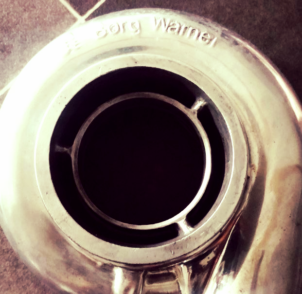
Haven't made any updates in a little while. I pulled off the compressor housing and sent it off for some secret work. Stay tuned for the results in a week or so here Also installed oil temperature gauge, so when I get it up and running we'll have some oil vs coolant temp numbers. I'm curious to see the difference in oil temps at idle vs cruise.
^ So you are suing the HKS compressor housing and the BW internals? Will be interested to see the changes in your dyno HP due to this.
Its all BW with BW internals
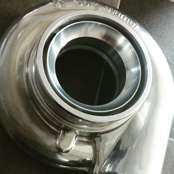
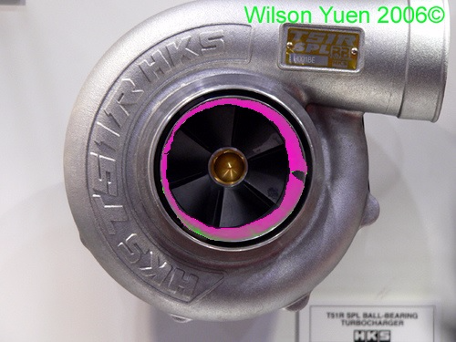
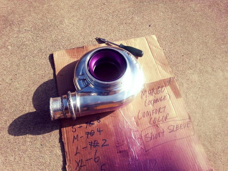
I sent it off to shop to have this done. The BorgWarner anti-surge/mapwidth section was cut out with a lathe. An aluminum insert was CNC'd to fit the BW housing, but scaled to match the turbulence/angles/width's of the HKS middle section. This center piece was then fitted into the compressor housing with set screws, which I painted before installing as now that it is removable its possible to paint so why not match the purple wastegate
There should not be any real world change in dyno numbers.
Rev'd it in neutral last night, screams at 4k.
Last edited by Monsterbox; Jul 9, 2015 at 09:36 AM.


 Cruising, temps drop to around 190F / 170f respectively. Fan controller reads off lower rad hose, so I set threashold to around 160F to anticipate actual 180F reading from top hose.


 LOVE the whistling sound!!!
