When you click on links to various merchants on this site and make a purchase, this can result in this site earning a commission. Affiliate programs and affiliations include, but are not limited to, the eBay Partner Network.
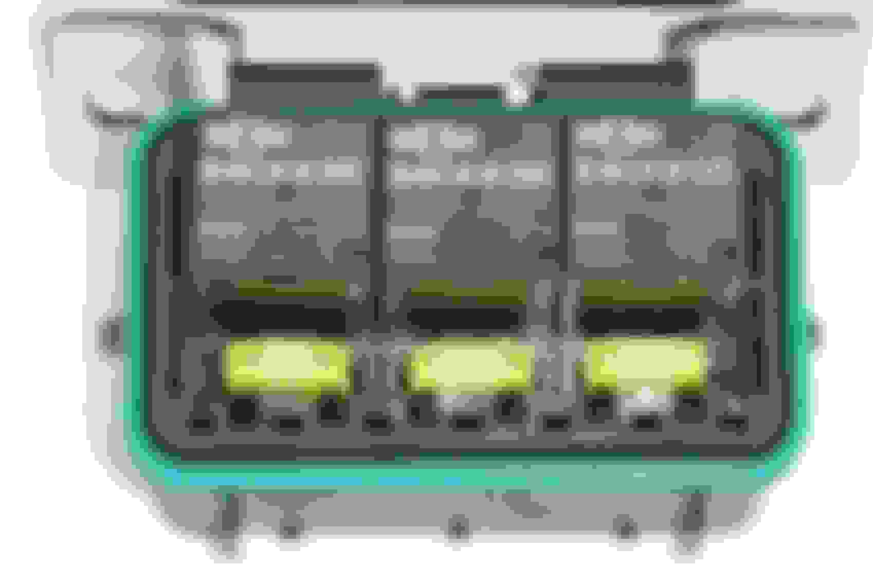
I'm upgrading to EFI on my '85 GSL and I was thinking of a clean way to add some circuits and tidy up the harness where the fusible links are. Littlefuse makes the HWB18 which is a modular panel that will give me just enough room for the following:
2 relays, one for ignition system (IGN-1A coils) and one for an electric fan
5 micro fuses, one for each of the original fusible links plus one for each of the above relays.
They also make a larger HWB60 which can hold significantly more circuits but I don't want to jump into that if I don't have to. So here come the questions I'm hoping you guys wouldn't mind taking a look at...
1) Any reason micro fuses shouldn't be used for the original fusible links?
2) What rating should I replace the 0.3sq and 1.25sq fuses with?
3) How much current will a 4-pack of IGN-1A coils and two injectors pull?
4) Should I plan on replacing the wiring and relay to the fuel pump if I am upgrading to a Walbro high pressure pump, or will the factory wiring be sufficient?
5) Are there any other relays and/or fuses you would suggest?
My goal is to be minimally invasive to the factory chassis harness since it's in good shape. I plan to remove the emissions computer from the passenger footwell, install an Adaptronic 440d, and reuse as much of the factory harness for the computer as possible. In the engine bay, I'll reuse the large engine harness connector but make my own engine harness that uses many of the original wire leads for different purposes. I believe there are enough connections between the original computer and the engine bay that I won't have to snake any extra wires through the firewall so the passenger side of the engine bay should basically look the same. On the driver's side of the engine bay I have already stripped out the wiring for the original coils and I'm working on how to wire things up nice and clean as well as add some better ground wires in the process.
Have you given thought to extra power demands you're installing,or maybe already done an alternator upgrade as i recall you have some audio upgrades. What do you have in this regard?
All the components you list will likely require at least a 30 amp alternator upgrade imo.
You will want at least a 3rd relay for fuel pump,use 12 ga. wire from relay to pump, run dedicated power and ground wires to pump,just as easy to run 2 wires as it is one and will insure minimum voltage drop in long run to pump.Pump will run cooler and last longer.
Not sure i'd trust the main fuse input to a mini fuse and the fuse rating for that circuit will depend on amperage rating of alternator. The 2 smaller fuselink circuits i'd fuse at 30 amps each for some reserve. Fuses will blow faster than the time it takes to melt a fuselink,in other words,fuselinks are more tolerant of temporary overdemand on circuit.
I'm sure the relay if rated for 30 amps and fused at that rating will be sufficient for all ignition coils.
Again for reserve,i'd want a cooling fan relay rated for at least 40 amps and would fuse that circuit for 60 amps. All fan motors on startup pull more current than is needed for spun up operation. The larger(cfm) fan,the larger the motor and associated load hit when 1st engaged.
What is your plan for powering the standalone ecm,do you have a specification for power consumption? I would have a dedicated circuit and diode type relay rated at 30 amps and fused for same. Non diode/resistor relays can cause system spikes on shutdown of high power consumers(cooling fan),personally i'd run them on ignition,fuel pump and fan circuits as well to prevent possibility of building in hiccups or driveability issues.
Not trying to poo poo your idea of littlefuse PDM. The idea is sound,the execution not so much as it's made in China. Have seen some reliabiity issues with their relays.
Another suggestion,upgrade to a 2nd gen fusebox. Keeping it Mazda,doesn't look out of place,has enough circuits for future expansion and the fuselink terminals in your car will plug right into the fuse receptacles on the bottom of fusebox. You can plug in a large main fuse and connect the alternator output and main feed to fusebox on one side of main fuse and the upgraded power cable that goes to battery positive on the other leg of fuse.Done.Clean.
I went this route with my SE. I wanted a solid base for upgrading my electrical system.I run hi/wattage headlamp bulbs thru a relayed harness and they draw a fair amount of current,probably 3 x what original lights drew. Also running a relayed 2nd gen DFI system.
I wanted room for future expansion,possibly upgrading to an electric cooling fan when and if the current fan clutch begins to fail and a possible standalone fuel system,gives you options. Gives much improved power window operation,on par with my modern DD.
I'm running a homemade 130 amp FD alternator and use a 130 amp main fuse in fusebox. I know i've seen somewhere on this site you can get a vinyl applique to put on fusebox lid that describes what circuit is fused and what amp rating it's fused to.
Still searching for vendor that makes them,i think i saw this in 2nd gen forum. Note this mod doesn't address the relays you'll need but 4/5 pin Bosch/Hella relays and relay mounting racks are readily available for a clean install.
Last edited by GSLSEforme; Nov 21, 2018 at 08:00 PM.
Having difficulties loading pictures to the site. I can gather them together from files on hard drive and click upload button at which point they disappear and don't show in post. Not 1st time this has happened, never had a problem before, something on site has changed?
Any ideas, suggestions, solutions?
1) Any reason micro fuses shouldn't be used for the original fusible links?
2) What rating should I replace the 0.3sq and 1.25sq fuses with?
3) How much current will a 4-pack of IGN-1A coils and two injectors pull?
4) Should I plan on replacing the wiring and relay to the fuel pump if I am upgrading to a Walbro high pressure pump, or will the factory wiring be sufficient?
5) Are there any other relays and/or fuses you would suggest?
1. the FC/FD style fuses will plug right in place of the Fusible links
2. no idea, there must be some table/chart somewhere. the fusible link is not in fashion right now, but they work just fine. anything else is basically just spending money and doing work for no benefit.
3. info has been posted about the coils, they draw a LOT of current, search for "the coil thread" in the NA section. for injectors it depends on the impedance. you simply use ohms law, 12v/15 ohms impedance = 0.8amps, each.
4. the factory wiring is probably fine.
5. the stock stuff might not be cool, or very shiny, but it does work.
1. Fusible links are not like regular fuses. Fusible links are slow-blow fuses.
A normal fuse will blow almost immediately if its amp rating is exceeded, this prevents a fire from a sudden short or excessive draw. A fusible link or slow blow fuse is able to have its amp rating exceeded for a short period of time without blowing, this is to allow it to handle surges that can occur normally in the operation of a car (electric motors starting, headlights turning on, etc.). If you replace your fusible links with fuses, you're likely to have a headache of repeatedly blowing them.
Because there aren't any 2nd Gen RX7's in junkyards where I live, I replaced my fusible links with a primary fuse box I pulled from a 90's Suzuki car. I just looked for something with a small separate cartridge-type fuse box in Japanese cars until I found it.
2. I think I used 50A for the main fusible link and 20A for the Headlight and Headlight Motor links.
4. The factory wiring is 30 years old, and insufficient fuel pressure causes a bunch of issues in EFI systems. I would suggest upgrading for peace of mind.
5. Adding relays for each connection on your ignition switch (ACC, IGN-A, IGN-B) will go a long way in keeping voltages high and preventing the contacts from getting burnt.
Have you given thought to extra power demands you're installing,or maybe already done an alternator upgrade as i recall you have some audio upgrades. What do you have in this regard? All the components you list will likely require at least a 30 amp alternator upgrade imo.
Yes, I have a brand new FC alternator I plan on using.
You will want at least a 3rd relay for fuel pump,use 12 ga. wire from relay to pump, run dedicated power and ground wires to pump,just as easy to run 2 wires as it is one and will insure minimum voltage drop in long run to pump.Pump will run cooler and last longer.
Ok, I was hoping I didn't need to do this, but I'll run a pair of wires back there and figure out a better way to click on the pump that doesn't use the factory relay. I may leave this for after I get things running since I don't want to pull the interior to run wires if I don't have to.
Not sure i'd trust the main fuse input to a mini fuse and the fuse rating for that circuit will depend on amperage rating of alternator. The 2 smaller fuselink circuits i'd fuse at 30 amps each for some reserve. Fuses will blow faster than the time it takes to melt a fuselink,in other words,fuselinks are more tolerant of temporary overdemand on circuit.
Ok, I didn't really think about the links and their slow-burn capability. I didn't use any links when I did my REPU harness and it hasn't popped any fuses, but I used standard blade fuses, not mini fuses.
I'm sure the relay if rated for 30 amps and fused at that rating will be sufficient for all ignition coils. Again for reserve,i'd want a cooling fan relay rated for at least 40 amps and would fuse that circuit for 60 amps. All fan motors on startup pull more current than is needed for spun up operation. The larger(cfm) fan,the larger the motor and associated load hit when 1st engaged.
That seems overkill. I was planning to use a spal 16" and I got by with only 30a fuse and relay for that in my REPU. It hasn't failed me yet but it does draw quite a bit of power on start-up. The wiring kit I started with was made by American Autowire and the supplied fan relay failed within the first week and I had to replace it with one from the parts store. It's been fine since.
What is your plan for powering the standalone ecm,do you have a specification for power consumption? I would have a dedicated circuit and diode type relay rated at 30 amps and fused for same. Non diode/resistor relays can cause system spikes on shutdown of high power consumers(cooling fan),personally i'd run them on ignition,fuel pump and fan circuits as well to prevent possibility of building in hiccups or driveability issues.
It's an Adaptronic 440d. I honestly was thinking it's power consumption would likely be less than a 30 yr old emissions computer and I might not have to upgrade the power wire or circuitry going to it. Afterall, the original wiring had some pretty hefty electronics like solenoids and a carburetor heater. I tried to find the power consumption of the ECU but as you may know, Adaptronic was bought by Haltech and the manuals and online tutorials have disappeared. I installed the dual Innovate Motorsports wideband O2 sensors before anything else. Those are wired off some spare power connections and grounds I found in an unused harness in the passenger floor. They take a little longer than expected to heat up, but they aren't popping any fuses.
Originally Posted by GSLSEforme
Not trying to poo poo your idea of littlefuse PDM. The idea is sound,the execution not so much as it's made in China. Have seen some reliabiity issues with their relays.
Another suggestion,upgrade to a 2nd gen fusebox. Keeping it Mazda,doesn't look out of place,has enough circuits for future expansion and the fuselink terminals in your car will plug right into the fuse receptacles on the bottom of fusebox. You can plug in a large main fuse and connect the alternator output and main feed to fusebox on one side of main fuse and the upgraded power cable that goes to battery positive on the other leg of fuse.Done.Clean. I went this route with my SE. I wanted a solid base for upgrading my electrical system.I run hi/wattage headlamp bulbs thru a relayed harness and they draw a fair amount of current,probably 3 x what original lights drew. Also running a relayed 2nd gen DFI system.
I wanted room for future expansion,possibly upgrading to an electric cooling fan when and if the current fan clutch begins to fail and a possible standalone fuel system,gives you options. Gives much improved power window operation,on par with my modern DD.
I think I would sooner move to some other aftermarket solution than pick up a 2nd gen box. I'd rather just click and buy all the wire terminals I need and have something modular and water tight than be forced into a specific layout of an OEM system. I used the smaller littlefuse relays on my REPU for high/low beams and high/low wipers. They have been working great so far. The lights are super bright compared to the original harness and the wipers...well they work, I think the motor ground needs to be fixed and the bushings need to be replaced. They work as well as they did before, which is to say they could get me home in the rain. I also used them for the fuel pump and EFI related circuits. There was one day when I could have sworn the EFI relay stuck on and the car kept running...but it only happened once and hasn't happened again since. It was like I turned the key off, and for a split second the car stayed running.
So anyway, I'm going to read through all these suggestions one more time but I think I'm just going to keep the factory fusible link panel as-is. I may use something like the box in the photo above, but not for those main circuits. Since it fits three relays, one for the fan, fuel pump, and coils may suffice, each with their own fuse. Everything else (including the ECU) will just stay on factory wiring circuits unless someone manages to convince me that the Adaptronic 440d is going to consume more current than the factory emissions computer and associated equipment.